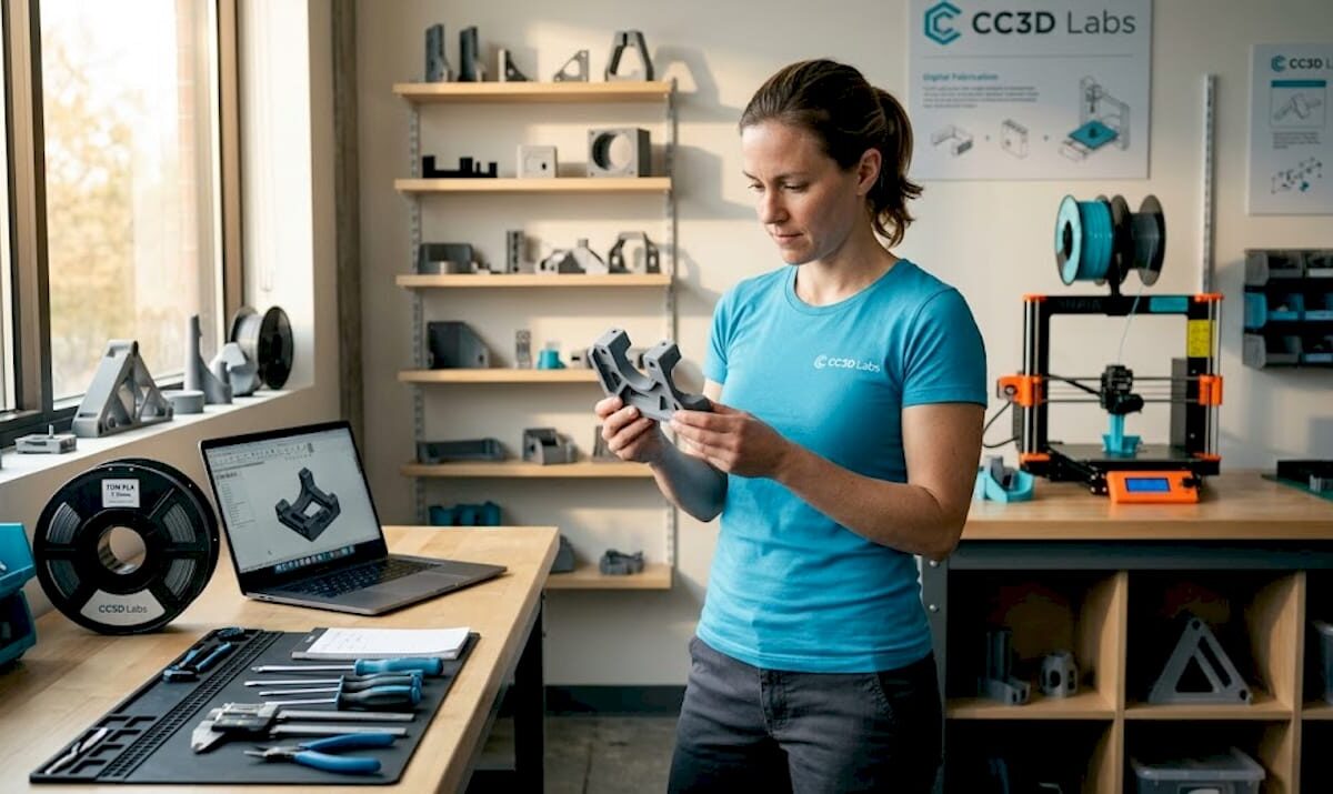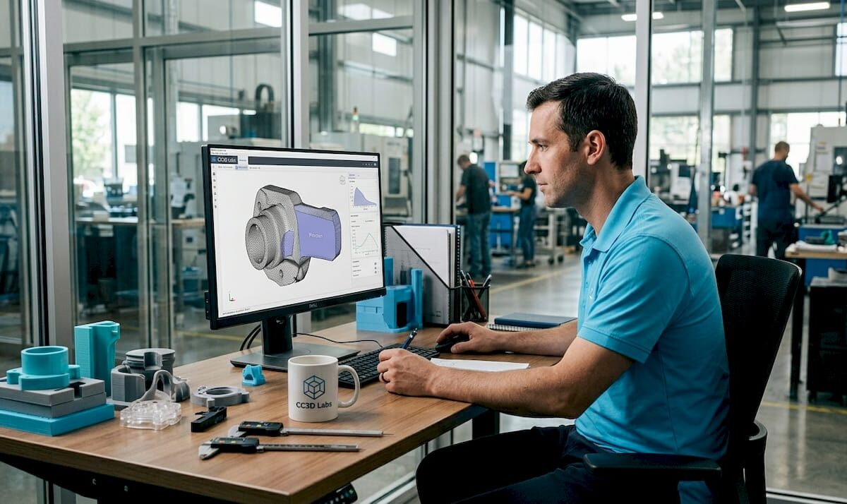
Engineer inspecting 3D printed parts at bench

Qualities of Precision 3D Parts Every Engineer Should Know


TL;DR:

  • Achieving true precision in 3D printing involves controlling tolerances, surface finish, and internal integrity throughout the entire process.
  • Effective collaboration between designers and manufacturers, along with comprehensive inspection methods like CT scanning, ensures consistent, high-quality parts ready for critical applications.

Understanding the qualities of precision 3D parts separates engineers who get functional assemblies right the first time from those who spend weeks chasing tolerance failures. Precision in additive manufacturing is not simply “the printer is accurate.” It covers dimensional tolerance control, surface integrity, material behavior, process repeatability, and post-processing effects working together. This article breaks down the specific technical characteristics that define a truly precise 3D printed part, how different technologies compare, and what process controls actually move the needle for engineers and product developers in 2026.

Table of Contents

Key takeaways

Point Details
Tolerance defines function High-precision parts target ±0.05 mm to ±0.1 mm, but the full print-to-finish process determines final dimensional accuracy.
Technology choice matters SLA and DLP deliver the tightest tolerances; SLS and DMLS trade some precision for structural complexity.
Precision includes the interior CT scanning per ASTM standards reveals internal defects that surface measurement alone cannot catch.
DfAM reduces tolerance failures Design for Additive Manufacturing strategies like strategic orientation and fillets prevent warping and dimensional drift.
Post-processing is part of precision Shrinkage, curing, and finishing steps materially affect final dimensions and must be controlled, not assumed.

1. The core qualities of precision 3D parts defined

Most engineers use “precision” as a catch-all, but manufacturing distinguishes three separate concepts: accuracy, precision, and repeatability. Accuracy means the part hits its nominal dimension. Precision means it hits the same dimension consistently across multiple prints. Repeatability means the entire process produces identical results across batches, machines, and operators.

High-precision printed parts commonly target dimensional tolerances of ±0.05 mm to ±0.1 mm, with layer heights as thin as 10 to 25 µm and surface roughness (Ra) values low enough to meet optical and medical standards. Industrial-grade systems achieve this through advanced process controls and active compensation for material shrinkage and thermal effects.

  • Dimensional tolerance: The allowable deviation from nominal geometry, typically expressed as ±X mm
  • Surface roughness (Ra): Average surface deviation in micrometers, directly affecting fit, friction, and sealing
  • Repeatability: Part-to-part consistency across a production run, not just a single successful print
  • Layer adhesion integrity: Uniform bonding between layers that prevents delamination under load
  • Build orientation effect: How the angle of a part on the build plate impacts anisotropic strength and dimensional accuracy

Pro Tip: When specifying tolerances for a printed part, always call out which surfaces are functional and which are cosmetic. Applying ±0.05 mm across an entire part inflates cost with no engineering benefit.

2. Tight dimensional tolerances and their effect on fit and function

Dimensional tolerance is the quality that most directly determines whether a part works in an assembly. A shaft that is 0.15 mm oversized will not seat in its bearing. A snap-fit feature that is 0.2 mm too thin will fail after three cycles.

For functional moving parts, engineered clearances of 0.2 to 0.4 mm are required in FDM to prevent fusion between adjacent surfaces during printing and enable proper articulation. This is not a flaw of the process. It is a designed-in reality that engineers must account for during modeling.

The important distinction is between as-printed tolerance and final tolerance. Shrinkage, curing, and finishing steps can materially alter final dimensional accuracy. A part that measures within spec on the build plate may drift outside tolerance after thermal post-processing. Treating the full workflow as a single controlled capability, not just the print stage, is what separates production-ready precision from prototype luck.

3. Consistent surface finish and low roughness metrics

Surface finish affects more than aesthetics. It governs sealing performance, friction in moving assemblies, fatigue life under cyclic loading, and adhesion in bonded joints. Ra values below 1.6 µm are achievable with resin-based processes; industrial FDM typically produces Ra values between 6 and 25 µm before post-processing.
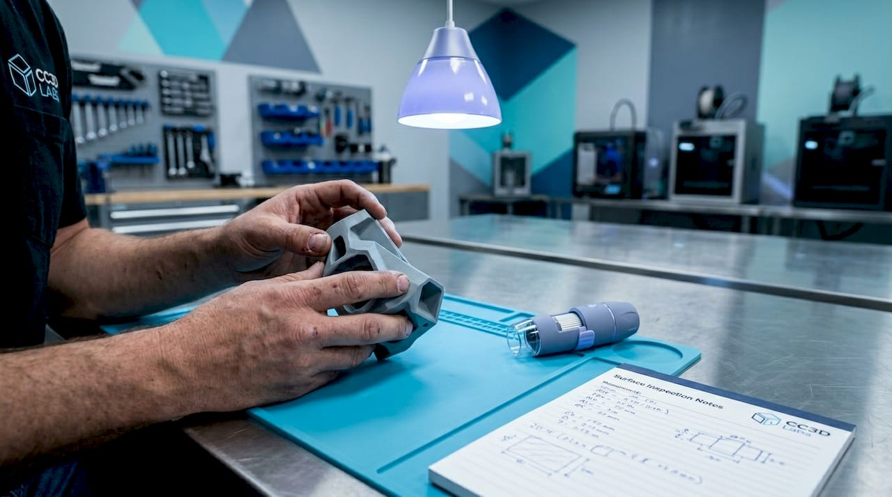
Hands inspecting 3D printed surface texture

Post-processing methods change this significantly. Vapor smoothing reduces surface roughness in FDM parts by 70 to 90 percent in some cases. Bead blasting improves surface uniformity in SLS parts while reducing friction in joints. CNC machining of critical surfaces brings any printed part to sub-micron roughness when required.

The practical implication: specify surface finish by Ra value on your technical drawing, not by process. Let the manufacturer select the combination of printing and finishing that hits the number. You get better results and more flexibility in sourcing.

4. Feature resolution and minimum wall thickness

Fine features are where many additive processes fail quietly. A design that looks correct in CAD can lose detail, round edges, or merge adjacent features when translated into physical layers.

Minimum wall thickness for FDM typically runs 0.8 to 1.2 mm for structural reliability. SLA and DLP push that down to 0.3 to 0.5 mm. DMLS for metal parts holds around 0.3 to 0.4 mm. These numbers change with build orientation: walls parallel to the Z axis are generally thinner and more fragile than walls built horizontally.

The characteristics of high-quality 3D models include geometry that accounts for these physical limits. Features that are thinner than the process minimum either print poorly or not at all. Reviewing your model against the capabilities of your chosen process before sending it to print saves significant rework time.

5. Volumetric integrity verified through CT scanning

External dimensional inspection only tells part of the story. Internal porosity, incomplete fusion, entrapped powder, and micro-cracks are invisible to calipers and CMMs. These defects are particularly consequential in aerospace, medical, and pressure-vessel applications where internal flaws cause catastrophic failure.

CT inspection for additive manufacturing provides volumetric nondestructive testing for internal defects and dimensional verification beyond surface measurement, guided by ASTM standards E3166 and F3624. It reveals porosity and lack-of-fusion defects that are essential to catch in aerospace and medical quality assurance workflows.

This is not just an inspection technique. It is a process feedback tool. When CT results show consistent porosity at a specific layer height, that points directly to a process parameter issue. Catching it early across a batch prevents an entire production run from failing qualification.

Pro Tip: For certification-bound parts, request a CT scan report as part of your first article inspection package. It closes the loop between dimensional compliance and internal integrity in a single document.

6. Material homogeneity and post-processing effects

Material behavior during and after printing directly shapes the final precision of a part. Polymers shrink as they cool. Resins shrink during UV curing. Metals contract during sintering and heat treatment. Each process has a characteristic shrinkage profile that must be compensated in the pre-print CAD model.

Tight tolerances in metal additive manufacturing require thermal control, pre-compensated CAD models, and rigorous post-print inspection to avoid dimensional failures in aerospace and medical implants. That compensation is not a one-time correction. It is a machine-specific, material-specific, geometry-specific calibration that changes when any of those variables change.

Material homogeneity also matters for anisotropic strength. FDM parts are measurably weaker in the Z axis than in XY due to layer-to-layer bonding mechanics. Knowing this allows you to orient critical load paths in the XY plane at the design stage, rather than discovering the failure mode during testing.

7. Comparison of printing technologies by precision capability

Different processes achieve different tolerance levels, and selecting the right one for your precision requirement is a core decision. Here is a direct comparison of the major technologies:

Technology Typical tolerance Min feature size Best use cases
SLA ±0.05 mm 0.3 mm Dental, optics, microfluidics
DLP ±0.05 mm 0.3 mm Jewelry, hearing aids, small complex parts
PolyJet ±0.05 mm 0.2 mm Multi-material prototypes, overmold simulation
SLS (polymer) ±0.1 to 0.2 mm 0.5 mm Functional parts, complex geometry, no supports
DMLS (metal) ±0.1 to 0.2 mm 0.3 mm Aerospace, medical implants, tooling
Industrial FDM ±0.1 to 0.2 mm 0.8 mm Structural prototypes, jigs, fixtures

Resin-based technologies like SLA and DLP offer tolerances around ±0.05 mm with fine feature resolution, making them ideal for dental and microfluidic applications. Powder-based processes like SLS and DMLS achieve slightly broader tolerances but excel in functional structural parts with complex internal geometry.

Choosing the right process means matching tolerance capability to the function of the part. For a consumer product prototype, industrial FDM may be entirely sufficient. For a flight-critical bracket, DMLS with CT verification is the correct choice. Review the full technology comparison guide before committing to a process for a new program.

8. Best practices and process controls for achieving precision

Achieving precision in additive manufacturing requires controlling inputs at every stage of the workflow:

  1. Apply DfAM principles from the start. Design for Additive Manufacturing strategies such as adding fillets, minimizing large flat surfaces, and orienting parts on the XY plane reduce warping and dimensional drift before the printer ever starts.
  2. Use software compensation for shrinkage. Pre-scale the CAD model based on known material shrinkage coefficients for the specific machine and material combination. This is especially critical in metal DMLS and photopolymer SLA.
  3. Control the build environment. Temperature, humidity, and machine calibration directly affect dimensional output. Well-maintained machines with calibrated build plates produce measurably tighter results than machines running with drift.
  4. Implement CT inspection for functional parts. CT per ASTM standards ensures repeatability and certification readiness beyond typical surface metrology.
  5. Document traceability per AS9102 Rev C. AS9102 Rev C standards establish requirements for characteristic accountability in first article inspection, including nominal values, tolerances, GD&T callouts, and verification outcomes for each design characteristic.
  6. Plan post-processing as a controlled step. Vapor smoothing, reaming, bead blasting, and CNC finishing are not afterthoughts. Each one affects final dimensions. Budget tolerances accordingly.

Pro Tip: Build a tolerance stack-up analysis before finalizing your 3D printing process. Account for the as-printed tolerance, expected shrinkage, and the effect of any finishing steps. That stack-up tells you whether your process is capable before you print a single part.

Understanding tolerances in 3D printing at the engineering level is the single most effective way to close the gap between what your CAD model shows and what you hold in your hand.

My honest take on precision in additive manufacturing

I’ve worked with enough engineers and product developers to know that the word “precision” gets used loosely. A lot of projects arrive at the printer with tight tolerances applied uniformly across the entire part drawing, with no post-processing plan and no inspection defined. Then everyone is surprised when the part doesn’t fit.

In my experience, the biggest precision failures don’t come from the printing process itself. They come from treating the print as the final step. Shrinkage, curing, and finishing steps materially affect final accuracy, and ignoring that reality costs time and money on every program.

What I’ve also seen is that CT scanning changes the conversation entirely for functional parts. CT inspection reveals internal defects that surface checks miss completely, and in aerospace and medical programs, that is the difference between a part that certifies and one that doesn’t.

My honest recommendation: get your designer and your manufacturer talking at the start of the project, not after first print failure. The best precision outcomes I’ve seen come from that collaboration. The worst come from throwing a completed drawing over the wall and expecting the printer to sort it out.

— Justin

How Cc3dlabs helps you achieve precision in every part

When precision is not optional, the process behind the print matters as much as the machine. Cc3dlabs brings together advanced FDM printing, professional handheld 3D scanning (accuracy to ~0.1 mm), and design support to help engineers and manufacturers hit their tolerance and quality targets from the first production run.

https://cc3dlabs.com

Whether you need a single prototype validated against your CAD model or a batch of functional parts with documented first article inspection, Cc3dlabs provides the precision 3D printing services and inspection capabilities to back it up. Their team can assist with material selection, DfAM reviews, post-processing planning, and 3D scanning verification to confirm dimensional compliance before anything ships. From concept validation to production-ready components, Cc3dlabs delivers the technical depth that precision programs demand.

Get a free online estimate and find out how Cc3dlabs can support your next precision project.

FAQ

What tolerance is considered precision in 3D printing?

High-precision 3D printed parts target dimensional tolerances of ±0.05 mm to ±0.1 mm, depending on the technology. SLA and DLP processes achieve the tighter end of that range, while FDM and SLS typically operate toward ±0.1 to 0.2 mm without post-processing.

How do I verify precision in a 3D printed part?

Surface metrology with calipers or a CMM covers external dimensions, but CT scanning per ASTM standards E3166 and F3624 is required to verify internal integrity and catch porosity or fusion defects invisible to surface measurement.

Does post-processing affect final dimensional accuracy?

Yes. Shrinkage, curing, vapor smoothing, and CNC finishing all alter final part dimensions. The full print-to-finish workflow must be treated as a single controlled capability, not isolated stages.

Which 3D printing technology is most precise?

Resin-based technologies, specifically SLA, DLP, and PolyJet, deliver the tightest tolerances around ±0.05 mm and are best for fine-feature applications. DMLS leads in metal precision for structural and certification-critical components.

What is DfAM and why does it matter for precision?

Design for Additive Manufacturing (DfAM) is the practice of adapting geometry to suit additive process constraints. Strategic orientation, fillets, and support design reduce warping and dimensional drift, directly improving the precision of the printed part without changing the machine or material.
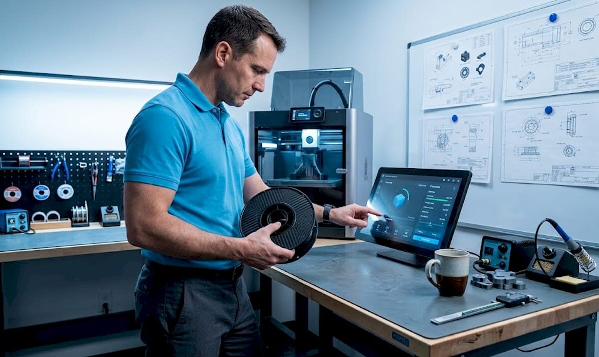
Engineer choosing filament for 3D printing in lab

Why Choose Filament for Engineering Parts: 2026 Guide


TL;DR:

  • Choosing the correct filament is essential for ensuring the performance, durability, and environmental resistance of engineering parts, preventing costly failures.
  • Selecting materials like PETG, nylon, or carbon fiber composites depends on mechanical, thermal, and environmental requirements, with proper process control and supplier reliability being critical for success.

Choosing the wrong filament for an engineering part is not just a performance issue. It can mean a failed prototype, a recalled product, or thousands of dollars in avoidable rework. The question of why choose filament for engineering parts goes deeper than picking the strongest material on the shelf. Engineering-grade filaments are selected for functional performance first, not ease of print, and the spectrum of available materials now spans simple PETG all the way to carbon fiber reinforced composites. Understanding that range, and knowing where each material fits, is what separates parts that work from parts that just look like they work.

Table of Contents

Key takeaways

Point Details
Filament choice drives part performance Mechanical properties like tensile strength and heat deflection temperature directly determine whether a part survives in service.
Environment shapes material selection UV, chemical exposure, and moisture can degrade the wrong filament quickly, making environmental fit as critical as strength.
Printability affects real-world outcomes A material with excellent specs on paper fails if your process cannot reliably print it without warping or delamination.
Cost-effectiveness goes beyond unit price Higher-cost filaments often reduce failure rates and iteration cycles, lowering total project cost over time.
Match material to application, not ego Over-engineering with premium filaments wastes budget. Selecting a fit-for-purpose material is a professional decision, not a compromise.

Why choose filament for engineering parts

Not all 3D printing filaments are created equal, and the engineering world proves that point daily. Professional material selection is a deliberate inquiry that balances load requirements, environmental conditions, and processing demands rather than simply reaching for whatever is labeled “strong.”

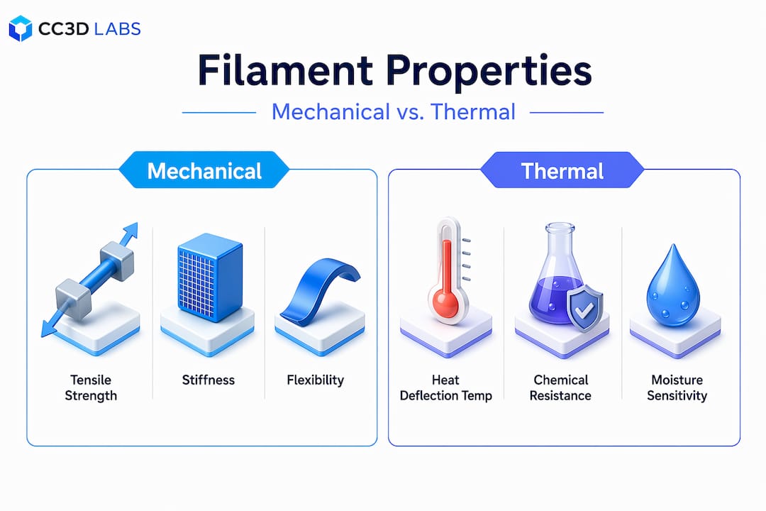
The core filament properties that determine suitability for functional parts fall into two categories: mechanical and thermal.

Infographic comparing mechanical and thermal filament properties

Mechanical properties that matter

Tensile strength tells you how much pulling force a part can take before it snaps. Stiffness, measured as elastic modulus, tells you how much it flexes under load. Toughness combines both into a measure of how much energy a part absorbs before fracturing. For engineers, toughness is often more useful than raw strength, especially for parts subject to impact or vibration.

Here is how common engineering filaments compare on key mechanical and thermal benchmarks:

Filament Tensile Strength (MPa) Heat Deflection Temp (°C) Best Use Case
PETG 50 80 Prototypes, housings
ABS 40 98 Interior structural parts
ASA 45 100 Outdoor structural parts
Nylon (PA12) 55 110 Wear parts, gears
Polycarbonate 65 130 High-load brackets
CF Reinforced 80+ 130+ Structural frames, jigs

Carbon fiber reinforced filaments deliver 2 to 3 times higher stiffness and heat deflection temperatures around 130°C compared to unfilled plastics. That gap matters when you are building jigs, fixtures, or any part that must hold dimensional tolerance under temperature cycling.

Thermal properties deserve equal attention. Heat deflection temperature (HDT) is the point at which a part begins to deform under load at elevated temperatures. Glass transition temperature (Tg) marks where the polymer structure softens. A housing printed in PETG with an 80°C HDT will warp inside a vehicle dashboard or near industrial heat sources. That failure is not a print defect. It is a material mismatch.

Technician testing 3D part heat resistance

Pro Tip: When specifying filaments for load-bearing parts, request the material’s datasheet from your supplier. Published HDT values tested under 0.45 MPa load are more conservative and more accurate for engineering use than values tested under 1.82 MPa.

Environmental resistance and filament choice

Knowing how a part performs in a lab is only half the picture. The environment where it will actually live determines whether a perfectly printed part survives a season outdoors, a chemical wash, or a humid warehouse.

The key environmental factors that should drive your filament selection are:

  • UV and weather resistance: ABS degrades noticeably under prolonged UV exposure. ASA filament provides superior UV and weather resistance, making it the go-to choice for outdoor parts that need to last years without significant degradation. It shares ABS’s strength and heat resistance while adding meaningful sunlight stability.
  • Chemical resistance: Nylon and polycarbonate can absorb certain solvents and degrade in acidic environments. PETG offers reasonable chemical resistance for many industrial cleaning agents. For aggressive chemical environments, check material-specific resistance charts before committing to a filament, or reference industrial pipe material guides to see how comparable polymers hold up in practice.
  • Moisture absorption: Nylon is highly hygroscopic. Uncontrolled moisture absorption does not just cause print failures. It directly degrades the mechanical properties of finished parts, reducing tensile strength and increasing brittleness over time. Parts printed from wet nylon are structurally compromised before they leave the printer.

Pro Tip: Dry nylon filament at 70 to 80°C for at least four hours before printing, and store it in a sealed container with desiccant. If you are running production quantities, an inline drying system attached to your printer feed is worth the investment.

For your outdoor parts selection, the Cc3dlabs guide covering outdoor-durable filaments breaks down the top material choices with real-world context.

Printability challenges with engineering filaments

Strong on paper does not mean easy to print. Engineering-grade filaments introduce processing requirements that general-purpose PLA users never encounter, and understanding those requirements before you start is how you avoid wasted prints and failed parts.

Here is the printability spectrum from accessible to highly specialized:

  1. PETG prints cleanly on most desktop FDM machines with a 230 to 250°C nozzle and a 70 to 85°C bed. Warping is minimal, and layer adhesion is reliable. It is the most accessible entry point for durable engineering parts.
  2. ABS and ASA require a heated enclosure to prevent warping, particularly on large footprint parts. Bed temperatures in the 100 to 110°C range and a consistent ambient temperature around 45 to 50°C are necessary for dimensional stability.
  3. Nylon needs a dry filament environment, high bed adhesion (PEI or garolite surfaces work well), and nozzle temperatures around 240 to 270°C depending on grade. Without proper drying, expect stringing, poor layer fusion, and degraded mechanical properties.
  4. Polycarbonate requires nozzle temperatures of 270 to 300°C and is highly prone to warping without an enclosed, heated chamber. It also absorbs moisture aggressively, so storage protocol matters.
  5. Carbon fiber composites need hardened steel or ruby-tipped nozzles. Standard brass nozzles wear out within a few hundred grams of CF-reinforced material. Carbon fiber reinforcement improves dimensional stability by locking the polymer matrix and reducing warping during cooling, which is a major advantage for complex or large parts.
  6. PEEK occupies its own category entirely. PEEK filaments require industrial-grade printers with nozzle temperatures between 360 and 450°C and bed temperatures from 120 to 160°C. Its use is only justified in extreme heat and chemical environments where no alternative material will hold up.

Bringing high-temperature filament capability in-house changes iteration economics significantly, shortening design-test-iterate cycles and reducing time-to-market for engineering teams working on complex assemblies.

Pro Tip: Before scaling a material to production volumes, run a print qualification test: print the same geometry in three separate batches from three separate spools. Variation between batches reveals supplier inconsistency before it becomes a production problem.

Cost-benefit analysis for filament selection

The sticker price of a filament spool is the least useful number in your cost analysis. What actually drives cost in filament-based engineering parts is the total cost of ownership: failed prints, post-processing time, rework rates, and iteration cycles.

Consider this comparison:

Filament Approx. Cost per kg Failure Rate (Est.) Best Total Cost Scenario
PETG $25 to $40 Low High-volume functional prototypes
Nylon PA12 $50 to $80 Medium (if wet) Gears, wear parts
Polycarbonate $60 to $100 Medium-High Structural load applications
CF Nylon $80 to $150 Low (with right setup) Stiff structural components
PEEK $200 to $400+ High without industrial hardware Extreme environments only

PETG is a pragmatic starting material for durable parts not exposed to extreme heat or chemicals. It combines printability with reasonable toughness and is widely available from consistent suppliers. For many functional parts, PETG delivers everything you need at a fraction of the cost of exotic materials.

The trap engineers fall into is over-engineering the material when the design is the actual problem. A polycarbonate bracket printed with poor layer adhesion will outperform nothing. A well-designed PETG bracket printed with optimal parameters will outlast a badly printed polycarbonate one every time.

Pro Tip: Before jumping to premium filaments, audit your print parameters and part design first. Most real-world failures in functional filament parts come from inadequate wall thickness, poor infill strategy, or moisture-degraded material, not from choosing the wrong polymer family.

Real-world applications across filament types

Theory becomes useful when you can connect it to specific parts solving specific problems.

  • Outdoor enclosures and mounting brackets: ASA is the clear choice. Engineering teams building antenna mounts, sensor housings, or outdoor junction boxes routinely use ASA to get ABS-level toughness without the UV degradation risk. Parts produced with ASA maintain structural integrity and color stability after years of direct sun exposure.
  • Wear-resistant sliding parts and bearings: The Igus Iglidur i190PF filament achieves wear rates 100 times lower than standard PETG, tested in a dedicated tribology laboratory against stainless steel. For lubrication-free bushings, guide rails, or any sliding contact application, this class of material changes what is achievable with FDM printing.
  • Structural prototypes and tooling jigs: Carbon fiber reinforced nylon or PETG delivers the stiffness needed for jigs, fixtures, and assembly aids. The dimensional stability under temperature cycling makes CF composites far more reliable than unfilled materials for production floor tooling, where tolerances matter every shift.
  • Functional prototypes bridging to production: PETG and ABS occupy a productive middle ground for prototype engineering parts where you need real mechanical behavior data without committing to expensive materials or processes. They print predictably, iterate quickly, and are cheap enough to run multiple design variants in a single day.

My take on filament selection in the real world

I have seen engineering teams spend weeks debating whether to use carbon fiber reinforced nylon versus PEEK for a bracket that operates at room temperature with a 20-pound static load. That debate was not an engineering decision. It was anxiety wearing the costume of rigor.

In my experience, the biggest mistake engineers make when selecting filaments is conflating material prestige with material fitness. The best filament for your part is the one that meets your mechanical, thermal, and environmental requirements at the lowest total cost with the highest print reliability. Full stop.

What I have found actually separates strong filament workflows from weak ones is not the material choice. It is the testing discipline. Teams that run small print qualification batches before committing to a material, that document their failure modes, and that track print parameters across suppliers iterate faster and waste far less than teams that treat every print as one-off experimentation.

Supplier quality is also wildly underrated. The same nominal filament from two different manufacturers can produce measurably different mechanical outcomes. Diameter consistency, moisture control during shipping, and formulation stability vary more than most engineers expect. Finding a reliable supplier and sticking with them across a project is a real process advantage.

Finally, building your material knowledge through deliberate iteration beats reading datasheets alone. Print the same geometry in three materials. Load test them. Break them. The result will tell you more than any specification document.

— Justin

How Cc3dlabs supports your engineering parts workflow

Working with engineering-grade filaments in-house is a significant capital and process investment. Cc3dlabs offers a ready alternative for teams that need production-quality filament parts without building the infrastructure from scratch.

https://cc3dlabs.com

From functional prototypes in PETG and ASA to advanced composite prints for structural applications, Cc3dlabs handles the material selection, process optimization, and quality validation so your team can focus on design. Their 3D printing services cover everything from single prototype prints to batch production runs, with fast turnaround and material guidance built into the engagement. If your project involves complex geometries, tight tolerances, or high-performance filament requirements, their team near Philadelphia offers both local pickup and shipping, backed by a track record of print accuracy that engineering applications demand. You can also explore how 3D printing drives product innovation to see where filament-based manufacturing fits in the broader product development picture.

FAQ

What filament is best for functional engineering parts?

The best filament depends on your specific load, temperature, and environmental conditions. PETG suits most prototypes and housings, while nylon, polycarbonate, and carbon fiber composites are better for higher-stress or high-temperature applications.

Why use filament instead of other manufacturing methods?

Filament-based 3D printing offers rapid iteration, low tooling cost, and the ability to produce complex geometries without fixturing. It is especially effective in early-stage development when design changes are frequent and speed matters more than per-unit cost.

How does moisture affect engineering filament parts?

Hygroscopic filaments like nylon absorb moisture from the air, which degrades both print quality and finished part strength. Drying filament before use and storing it with desiccant are non-negotiable steps for reliable engineering outcomes.

Is PETG strong enough for load-bearing parts?

PETG handles moderate loads well, with a tensile strength around 50 MPa and an HDT of roughly 80°C. For parts exposed to higher temperatures or impact forces, upgrading to polycarbonate or a carbon fiber reinforced filament delivers meaningfully better performance.

When does it make sense to use PEEK filament?

PEEK is justified only when a part must survive extreme heat above 200°C or aggressive chemical environments where no other filament will hold up. Its processing demands and cost make it impractical for most standard engineering applications.

Technician examining 3D printed part in workshop

Explaining 3D Print Durability: What You Need to Know


TL;DR:

  • Durability in 3D printed parts depends on optimal material choice, print orientation, and design features tailored to stress conditions.
  • Materials like nylon and carbon fiber composites outperform PLA and resin in impact resistance and long-term strength, especially outdoors.

Most people assume 3D printed parts are fragile curiosities, good for display models and little else. That assumption is wrong, and explaining 3D print durability correctly requires looking past surface-level impressions. The right material, print settings, and part design can produce components that handle real mechanical loads, survive harsh environments, and last for years. This guide breaks down exactly what drives durability in 3D printed parts, from material choice and layer orientation to environmental exposure, so you can make decisions that actually hold up under pressure.

Table of Contents

Key takeaways

Point Details
Material choice drives durability Nylon and carbon fiber composites outperform PLA significantly in impact resistance and long-term toughness.
Orientation determines strength direction Parts fail along the Z-axis first, so orienting critical load paths in the X/Y plane is non-negotiable.
Walls beat infill for surface strength Adding more perimeter walls resists crack propagation better than pushing infill above 30%.
Environment degrades materials over time UV exposure, humidity, and chemical contact all reduce longevity differently depending on the material.
Process and design must align Chasing high tensile strength numbers means nothing if print orientation and wall count undercut real-world performance.

Explaining 3D print durability through material properties

When people talk about the durability of 3D printed materials, they often collapse several distinct mechanical properties into one vague concept. Real durability covers tensile strength, impact resistance, stiffness, ductility, and fatigue resistance. A material can score high on one and fail badly on another. Strength is multifaceted, and selecting the right material means matching the right combination of properties to the specific stress your part will face.

Here is how the most common materials stack up:

  • PLA is the most popular filament and the least durable for functional use. It prints easily, holds decent tensile strength on paper, but becomes brittle under impact and starts to deform around 60°C. It works for display models and low-stress brackets, not load-bearing parts.
  • ABS improves on PLA in heat resistance and impact toughness, tolerating temperatures up to roughly 100°C. It warps during printing if conditions are not controlled, but the finished part handles moderate mechanical stress better.
  • PETG sits between PLA and ABS in most categories. It offers good layer adhesion, chemical resistance, and a balance of flexibility and stiffness that makes it popular for functional enclosures and PC components. PETG and ABS material comparisons show why PETG is often the go-to for durable everyday parts.
  • Nylon is the toughest thermoplastic available for desktop 3D printing, combining high impact strength with enough flexibility to absorb energy rather than crack. It absorbs moisture from the air, so storage and drying matter, but for demanding mechanical applications it leads the pack.
  • Carbon fiber composites take stiffness further than any standard filament. Short-fiber reinforced nylon or PETG resists flexing under load, making it popular in industrial jigs, brackets, and structural prototypes. The tradeoff is brittleness compared to pure nylon.
  • Resins (SLA/MSLA) produce highly detailed parts with smooth surfaces, but their durability profile differs significantly. They tend toward brittleness and are sensitive to UV degradation over time.
Material Tensile Strength Impact Resistance Heat Resistance Best Use
PLA Moderate Low Low (~60°C) Display, low-stress parts
ABS Moderate Moderate Medium (~100°C) Enclosures, functional parts
PETG Moderate-High Moderate Medium (~80°C) Functional parts, PC components
Nylon High Very High High Mechanical, load-bearing parts
CF Composite Very High Moderate High Industrial, structural parts
Resin Moderate Low Low-Medium Detail models, dental, short-term use

Material gets you into the game. Print settings and part design win or lose it. Understanding 3D print toughness at the process level is where most projects go wrong, because people assume default settings produce adequate parts.

3D print tensile strength is directional. Parts printed in FDM are built layer by layer, which means bonding between layers is weaker than the material strength within a layer. Load applied across layers (Z-axis) will cause failure far sooner than load applied along the print plane. Anisotropic mechanical behavior is not a flaw you can engineer away entirely. It is a fundamental property of layer-based manufacturing that you have to design around.

The most impactful settings and design choices include:

  • Print orientation. Align the primary load path along the X/Y plane whenever possible. If your part resists bending along its length, print it lying flat rather than standing upright. For parts resisting pull or tension, the fibers should run parallel to the force direction.
  • Wall count over infill. Failures commonly start on outer surfaces, making perimeter walls more critical than interior density. Three to five walls create a thick shell that prevents cracks from propagating inward, even with modest infill.
  • Infill type and percentage. Gyroid and cubic infill patterns distribute load in multiple directions better than grid or lines. Beyond roughly 20 to 30% density, adding more walls produces better durability gains than pushing infill higher.
  • Layer height. Thinner layers mean more surface area between layers, which improves layer adhesion and overall part strength. Thicker layers print faster but reduce inter-layer bonding.
  • Avoid sharp internal corners. Stress concentrates at corners. Fillets and generous radii on internal features distribute load across a larger area and reduce crack initiation points.

Pro Tip: If you are printing a functional bracket or tool and wondering whether to increase infill from 30% to 60%, stop. Add two more perimeter walls instead. The part will be more crack-resistant, print faster, and use less material.

For deeper guidance on applying these principles before production, designing reliable 3D printed parts covers how design decisions compound with process choices for better outcomes.

Environmental factors and long-term longevity

A part that performs perfectly on day one can degrade significantly over months depending on where it lives. Factors affecting 3D print durability over time include UV exposure, moisture, chemical contact, and temperature cycling. Each material responds differently, and ignoring the end-use environment during material selection is a common source of premature failure.

Weathered 3D print outdoors showing degradation

UV and sunlight break down polymer chains in most standard materials. PLA degrades noticeably after extended outdoor exposure, becoming brittle and discolored within a season. ABS handles UV slightly better but still fades and weakens. PETG and ASA are significantly more stable outdoors. If your part lives outside, material choice is not optional. Outdoor 3D printed materials should be selected specifically for UV stability, not just mechanical strength.

Moisture is a persistent threat for nylon parts in particular. Nylon absorbs water from ambient humidity, which changes its mechanical properties. Printed nylon used in a dry warehouse behaves very differently from the same part in a humid coastal environment.

Resins face a specific durability challenge. Incomplete curing or improper washing of printed resins increases water absorption and color instability, reducing long-term durability. Dental resins show adequate short-term performance over six to twenty-four months, but their flexural strength and fatigue resistance lag behind milled ceramic or metal alternatives over the long term.

Specialty applications have driven interesting solutions at the material engineering level. Research into nano-calcium carbonate additives shows improved matrix density and chemical resistance in 3D printed cementitious materials at roughly 2% dosage. Similarly, nano-SiO2 at 7% concentration in resin composites improved wear resistance and compressive strength in structural honeycomb prints, though pushing concentration to 9% reversed those gains due to particle clumping.

For most practical applications, the takeaways are straightforward. Match your material to the actual environment the part will experience. Post-process resins properly and completely. Protect UV-sensitive materials with paint or coatings when used outdoors.

Real-world durability: from hobby projects to industrial parts

Maximizing 3D print durability looks very different depending on what you are building. Hobbyist tools and professional production parts operate in completely different performance brackets.

  1. PC case accessories and cable management parts printed in PETG or ABS handle the mechanical stress of regular use well. They clip, flex, and fasten without snapping. For this use case, PETG is the default choice among experienced makers because of its balance of toughness and printability.
  2. Functional brackets and mounts in mechanical environments benefit most from nylon or carbon fiber composites. These materials handle vibration, repetitive loading, and incidental impact without fatigue cracking that would destroy a PLA version within weeks.
  3. Industrial prototypes and jigs regularly use glass-filled or carbon-fiber-filled engineering thermoplastics. The orientation of fiber-reinforced composites dramatically affects results. Wood-polymer composite research demonstrates that optimized 0-degree orientation can produce hardness exceeding six times that of the natural source material, illustrating how process control multiplies material performance.
  4. Dental and medical resin prints serve well in short-term clinical applications where detail and biocompatibility matter. For long-term load-bearing use, however, their lower fatigue resistance compared to milled alternatives limits their application range.
  5. Outdoor structural or enclosure parts demand UV-stable materials like ASA or weatherable PETG blends, and should include design features like drain holes and overlapping geometry to prevent water pooling that accelerates degradation.

The pattern across all these examples is consistent. Durable 3D printed parts emerge from aligning material properties, print settings, and design geometry with the specific demands of the application rather than applying generic defaults.

My take on what durability really comes down to

I have seen a lot of clients arrive with parts that failed and an assumption that the material was to blame. Nine times out of ten, the material was not the problem. The print orientation was wrong, or the designer added infill and called it done without touching wall count. Durability is rarely a single-variable problem.

What I find consistently true is that tensile strength numbers from a data sheet tell you almost nothing about how a part will perform in the real world. A material rated at 50 MPa tensile strength printed in the wrong orientation, with two walls and default infill, will fail at a fraction of that number. The mechanical properties you see on spec sheets are measured in ideal test conditions along the strongest axis.

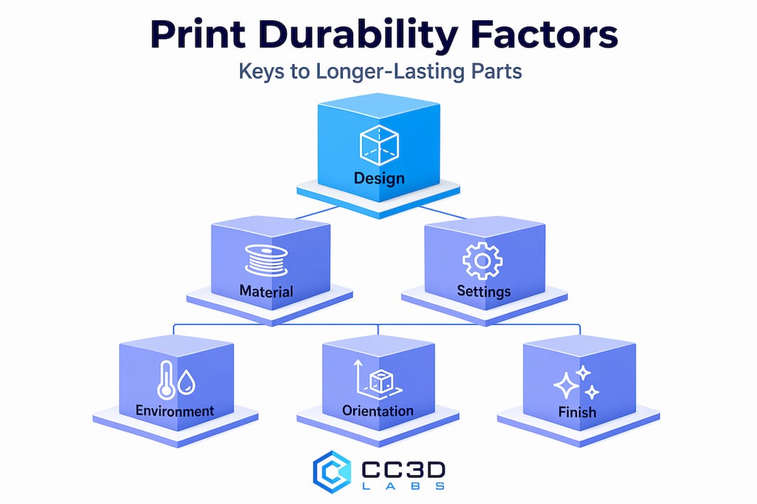
Infographic of main 3D print durability factors

The other thing I would push back on is the assumption that engineering materials automatically solve durability problems. I have watched carbon fiber composites fail on a bracket that was just printed at the wrong angle. The composite stiffness that makes it great in one direction makes it brittle in another. Understanding this is more useful than any spec sheet comparison.

My recommendation for critical applications is to validate your 3D designs before committing to production. Print test coupons in the intended orientation. Load them the way the final part will be loaded. The thirty minutes you spend on that test will tell you more than hours of reading material specs.

— Justin

Get durable 3D printed parts from Cc3dlabs

If this article has you thinking carefully about material selection, orientation, and design for your next project, Cc3dlabs can take that further with hands-on expertise. Based near Philadelphia, Cc3dlabs handles everything from single prototypes to batch production runs, with material knowledge that matches the right filament to the real demands of your application.

https://cc3dlabs.com

Whether you need a structurally sound bracket, a functional prototype that will survive testing, or production parts built for longevity, the team at Cc3dlabs applies the same principles covered here at every step. Explore professional 3D printing services or request a free online estimate to get started with parts that are built to last, not just built.

FAQ

What is the most durable material for 3D printing?

Nylon is the toughest standard thermoplastic for FDM printing, offering high impact resistance and flexibility. Carbon fiber composites provide the highest stiffness and are preferred for structural industrial parts.

Why do 3D printed parts fail along layer lines?

Tensile strength in 3D prints is directional because layer-to-layer bonding is weaker than the material within a layer. Parts loaded across the Z-axis fail first at those inter-layer boundaries.

Does higher infill percentage mean a stronger part?

Not beyond about 20 to 30% infill. Adding more perimeter walls is more effective for resisting crack initiation and surface failure than continuing to increase infill density.

How durable are resin 3D prints compared to filament prints?

Resin parts offer excellent detail but lower impact resistance and fatigue strength than engineering filaments like nylon. Short-term durability is adequate for many uses, but improper post-processing significantly reduces long-term performance.

Can 3D printed parts be used outdoors long-term?

Yes, with the right material. PLA degrades quickly under UV and moisture. ASA, weatherable PETG blends, and properly coated ABS handle outdoor conditions far better, especially when the part design avoids water traps.

Engineer reviewing 3D scan data in office

Why 3D Scan Data Integrity Is Crucial for Manufacturing


TL;DR:

  • High-resolution scans alone do not guarantee usable data, as accuracy, repeatability, and traceability are essential for reliable 3D imaging. Environmental conditions, operator technique, calibration, and software processing all threaten data integrity, which must be systematically protected through calibration, controlled environments, and documented workflows. Ensuring data integrity accelerates manufacturing, reduces errors, and improves project outcomes by providing dependable, traceable scan results.

High-resolution scans look impressive, but resolution alone does not determine whether your data is usable. Understanding why 3D scan data integrity is crucial separates professionals who consistently hit tolerances from those who keep chasing errors back to the source. Data integrity covers accuracy, repeatability, traceability, and processing quality. Miss any one of those, and even a visually detailed point cloud can collapse your prototyping workflow before a single part is printed or machined. This article explains what integrity actually means in a scanning context, what threatens it, and how to protect it at every stage of your workflow.

Table of Contents

Key Takeaways

Point Details
Resolution does not equal accuracy A high-resolution scan can still contain dimensional errors that ruin a prototype or manufactured part.
Integrity is a system-level property Hardware, software, operator technique, and environment must all work together to produce trustworthy data.
Calibration is non-negotiable Regular, traceable calibration prevents measurement drift and keeps scan data defensible for manufacturing acceptance.
Environment and operator matter as much as hardware Temperature gradients, vibration, and poor scanning technique introduce errors that even premium scanners cannot correct.
Reliable data accelerates the entire workflow Confident scan data reduces rework, speeds up iteration, and lowers the cost of production errors.

Why 3D scan data integrity is crucial: the core concepts

Before you can protect data integrity, you need a precise definition of what it includes. Four concepts form the foundation: accuracy, resolution, consistency, and traceability. Most professionals use the first two interchangeably, and that habit costs time and money.

Accuracy vs. resolution

Resolution and accuracy serve fundamentally different functions. Resolution describes how much surface detail the scanner captures. Accuracy describes how close those captured dimensions are to the physical truth of the object. A scanner can produce a beautifully detailed mesh at 0.05 mm point spacing that still carries a 0.3 mm dimensional error. In a product development workflow, the detail impresses stakeholders during review. The dimensional error shows up as a misfit during assembly.

High resolution also carries a practical cost. Excessive point density inflates file size, bogs down mesh repair, and slows every downstream process from CAD alignment to slicing. Matching resolution to intended use is not a compromise. It is the correct engineering decision.

Technician repairing scan mesh at lab bench

Consistency and traceability

Infographic pyramid showing scan data integrity concepts

Reliable scan data depends on repeatability, not just one good result. If scanning the same part twice under identical conditions produces meaningfully different outputs, nothing in your workflow is defensible. Consistency lets you trust comparisons, revisions, and inspection sign-offs.

Traceability ties your scan results to a verifiable standard. Calibrated reference artifacts, documented scan settings, and formal quality reports are what transform a point cloud from a visual deliverable into a manufacturing document. Consider the difference between a scan submitted to a contract manufacturer alongside a formal quality report that documents control points, outlier handling, and calibration history versus one submitted without any of that context. The first one gets approved. The second one gets questions.

  • Accuracy: Dimensional closeness to the physical object, measured against traceable standards
  • Resolution: Point density and surface detail, which should be matched to the specific use case
  • Consistency: Repeatability across sessions, operators, and equipment states
  • Traceability: Documentation linking scan results to calibrated standards and documented procedures

Together, these four elements define what strong 3D scanning data reliability actually looks like in practice.

Common threats to scan data integrity

Understanding the risks is not about pessimism. It is about knowing exactly where to focus your attention. Data integrity in 3D scanning is an emergent property, meaning it arises from multiple interacting layers rather than from any single component. When vulnerabilities in those layers align, even a capable scanner produces flawed data. This is the Swiss-cheese model applied to metrology workflows.

Here are the most common sources of failure, ranked by how often they are overlooked:

  1. Environmental conditions. Temperature, lighting, and vibration are the most underestimated threats to scan accuracy. Thermal expansion in a part being scanned in a warm production floor can shift dimensions measurably between the start and end of a single scan session. Air temperature gradients create measurement drift that no post-processing step can fully undo.

  2. Operator technique. The scanning path, standoff distance, overlap between passes, and handling of reflective or dark surfaces all introduce variability. Two operators scanning the same part with the same scanner can produce outputs that differ by more than the printed tolerance on the drawing.

  3. Hardware calibration drift. Sensors drift. Mechanical components develop play. A scanner that produced accurate results six months ago may no longer meet its stated specifications if calibration has not been maintained. This is particularly dangerous because the data often looks normal while carrying hidden dimensional errors.

  4. Software processing errors. Registration algorithms, mesh smoothing filters, and hole-filling routines all make decisions that affect dimensional truth. Default settings are not optimized for every geometry or material. Blindly applying them without understanding the tradeoffs is a common source of data degradation.

  5. Multiple interacting failures. The Swiss-cheese model predicts that single layers of defense rarely fail catastrophically on their own. An error in any one area is manageable. When poor environmental control, a drift-affected sensor, and aggressive mesh smoothing align in the same workflow, the result is data that looks clean but fails downstream.

Pro Tip: Before a major scan session, run a reference artifact through your full workflow, from capture to processed mesh. If the output falls outside your expected tolerance range, stop and find the cause before scanning the actual part.

Best practices to protect and maintain data quality

Knowing the threats is useful. Having a system to counter them is what actually protects your data. Reliability is a system-level outcome driven by calibration, environment, operator discipline, and software controls working together. No single action is enough on its own.

Calibration and traceable standards

Calibrate your scanner on a scheduled basis using certified reference artifacts. Document every calibration event with date, environmental conditions, and results. This documentation is what makes your data defensible for manufacturing acceptance in contract environments.

Modern high-accuracy scanners in 2026 can achieve volumetric accuracy of 0.03 mm + 0.05 mm per meter using multi-line laser modes, but that performance is only realized when calibration is current and conditions are controlled.

Hardware selection and environment control

Factor What to prioritize What to avoid
Scanner grade Metrology or industrial grade with stable housing Consumer devices for tight-tolerance work
Connectivity Onboard processing with dual Wi-Fi to prevent data loss Wireless setups that stream raw packets without error correction
Environment Temperature-controlled, vibration-dampened, diffuse lighting Bright window light, HVAC drafts, concrete floors near heavy machinery
Surface prep Matte reference spray or targets for reflective/dark surfaces Relying on raw surface appearance without preparation

Software and post-processing controls

Do not treat post-processing as cleanup. Every filter and alignment decision is a data modification. Use the minimum smoothing necessary for your application. Document the processing settings applied to each dataset. For high-quality manufacturing scans, the goal is mesh fidelity to the physical object, not visual appeal.

Pro Tip: Save both the raw point cloud and the processed mesh as separate files. If an alignment or filtering decision turns out to be wrong during CAD review, you can reprocess from raw data without rescanning the part.

  • Align scans using physical reference targets, not just software-generated feature matching
  • Run mesh quality checks before exporting, including hole counts, intersecting faces, and non-manifold edges
  • Match your export format and polygon count to what the downstream tool actually needs

The business impact of accurate scan data

The significance of 3D data integrity becomes clearest when you trace it directly to project outcomes. Reliable scan data reduces costly downstream failures and builds confidence in every decision that follows the scan. That effect compounds quickly in iterative product development.

Consider a typical reverse engineering project. A product team scans an existing component to create a replacement part. If the scan carries a 0.2 mm accuracy error and the designer does not detect it, the CAD model inherits that error. The prototype is printed or machined to that incorrect model. The fit test fails. The team scans again, remodels, reprints. Each cycle costs time and materials. The root cause was never the printing or machining. It was the scan data.

The importance of 3D scan accuracy is equally clear in inspection workflows. When scan data is traceable and consistent, it serves as a legal and contractual record of part geometry at a specific point in time. That record supports quality sign-offs, warranty claims, and deviation approvals with documented evidence rather than verbal assurance.

  • Accurate scan data cuts the number of prototype iterations by giving designers a reliable baseline to work from
  • Clean, well-structured mesh files reduce prep time in CAD and slicing software, directly lowering labor costs per part
  • Traceability documentation supports ISO and AS9100 quality requirements, which matter in aerospace, medical, and automotive supply chains
  • Consistent data across scan sessions makes it possible to detect genuine part wear or tooling drift, rather than noise from scan variability

For teams doing rapid prototyping, the benefits of accurate 3D scans are not abstract. They show up in the number of design cycles completed per week, the scrap rate on first-article inspection, and the speed of design sign-off. Those are the metrics that determine project profitability.

My take on where most teams go wrong

I have reviewed a lot of 3D scanning workflows over the years, and the pattern that frustrates me most is not carelessness. It is misplaced focus. Teams spend considerable money on a premium scanner and then operate it in conditions that undermine every advantage the hardware offers. The scanner becomes a status symbol rather than a calibrated instrument.

The misconception I run into most often is that a higher price tag or a more impressive spec sheet guarantees better data. It does not. A well-operated mid-range scanner in a controlled environment with a disciplined operator consistently outperforms a high-accuracy instrument scanned on a vibrating factory floor by someone who has not been trained on the specific geometry they are capturing.

What I have learned from working through enough failed prototypes is that workflow discipline matters more than any single tool upgrade. Calibration schedules, environmental logs, processing documentation, and reference artifacts are unglamorous. They do not appear in marketing materials. But they are the actual mechanism by which good data gets produced reliably, not occasionally.

My honest recommendation is to build your scanning protocol before you buy your next scanner. Understand exactly what the workflow demands in terms of accuracy, consistency, and traceability. Then select hardware that fits that protocol. The teams that do this consistently produce better outcomes than teams chasing the highest-spec device without a system around it.

— Justin

Get reliable scan data with Cc3dlabs

If this article has clarified what 3D scan data integrity actually requires, the logical next step is working with a team that applies these principles on every project. Cc3dlabs provides professional handheld 3D scanning (accuracy to ~0.1 mm) services from our facility near Philadelphia, and data quality is built into the workflow, not treated as an afterthought. Every scan includes calibration verification, documented processing steps, and output quality checks designed to support prototyping and manufacturing use.

https://cc3dlabs.com

Whether you are reverse engineering an existing component, inspecting a manufactured part, or generating scan data for a new prototype, our 3D scanning and prototyping guide walks you through how we approach accuracy and reliability at each stage. For hands-on preparation before your next scan session, the scanning accuracy checklist covers the specific steps that prevent the most common sources of data degradation. When you are ready to move from scanning to production, our full printing and prototyping services handle everything from single prototypes to batch production runs with the same commitment to dimensional accuracy.

FAQ

What does 3D scan data integrity actually mean?

Data integrity in 3D scanning means the captured data accurately and consistently represents the physical object with traceable, documented quality. It covers accuracy, repeatability, and the controls used during capture and processing.

How is accuracy different from resolution in 3D scanning?

Accuracy measures dimensional closeness to the real object, while resolution measures how much surface detail is captured. A high-resolution scan can still contain significant accuracy errors that cause problems in manufacturing.

What are the biggest threats to scan data quality?

Environmental factors like temperature and vibration, calibration drift, operator technique, and uncritical post-processing are the most common causes of data degradation, and they interact to compound errors.

How do I know if my scan data is good enough for manufacturing?

Run the processed mesh through a dimensional comparison against a calibrated reference artifact, check mesh quality metrics including non-manifold edges and holes, and document the calibration state of your scanner at the time of capture.

Why does 3D scanning data reliability matter for prototyping?

Unreliable scan data propagates errors into every downstream step, from CAD modeling to print or machining. Catching and correcting those errors at the source saves multiple prototype cycles and the costs that come with them.