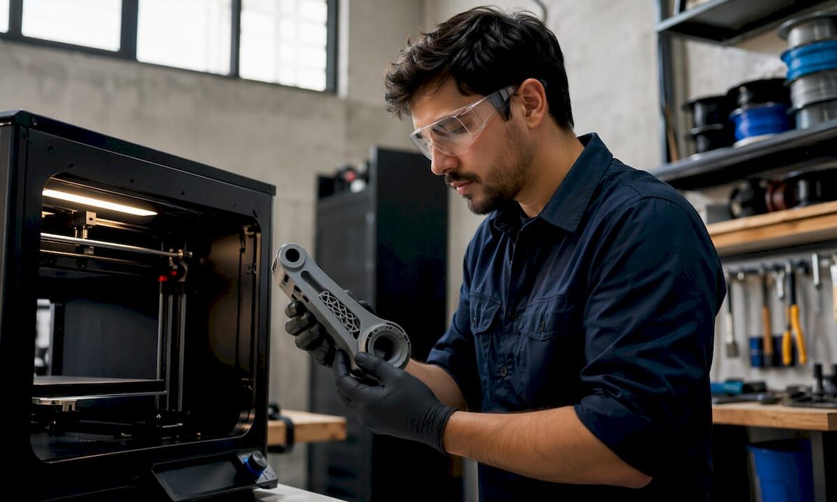
Technician removing 3D printed robot arm part

Building Custom Robot Parts With 3D Printing


TL;DR:

  • Additive manufacturing allows rapid creation of functional robot components directly from digital files. It enables customization of geometry and material, making prototyping faster and more accessible for small teams and individual developers. Proper design, material choice, and calibration are essential for producing durable, reliable robotic parts.

Additive manufacturing for robotics is defined as the process of producing functional mechanical components layer by layer from digital files, and it is the fastest way to go from concept to working prototype. Building custom robot parts with 3D printing gives engineers direct control over geometry, material, and iteration speed that traditional machining cannot match. A fully functional robotic arm can be built for around $220 in materials using standard servos and a desktop FDM printer. That cost point makes serious robotics prototyping accessible to individual developers and small teams for the first time.
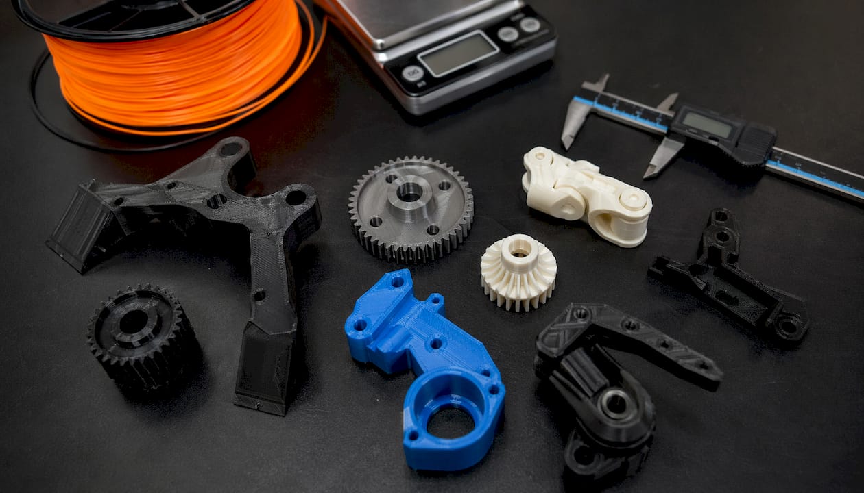
Detailed 3D printed robot parts on workshop table

What do you need to start building custom robot parts with 3D printing?

The right equipment determines whether your printed parts are functional or frustrating. Three printer technologies cover most robotics applications: FDM, SLA, and SLS. Each has a distinct role.

FDM printing offers fast, low-cost prototyping with visible layer lines and anisotropic strength. That means the part is stronger along the X and Y axes than along the Z axis. SLA produces high-resolution parts with smooth surfaces, which is useful for small linkages and sensor housings. SLS delivers isotropic strength and complex geometry without support structures, but at a significantly higher cost per part. For most product developers starting out, FDM is the correct first choice.

Choosing the right filament

Material selection is the single biggest variable in part performance. The table below summarizes the four filaments engineers use most often for 3D printed robot components.

Filament Strength Heat resistance Best use
PLA Moderate Low (~60°C) Prototypes, non-load-bearing frames
PETG Good Medium (~80°C) Structural brackets, enclosures
ABS Good High (~100°C) Housings, gears, functional parts
Carbon fiber reinforced High High Load-bearing arms, structural links

Carbon and glass fiber reinforced filaments provide higher stiffness and heat resistance but require careful print parameter tuning to avoid delamination. For a deeper breakdown of how these materials compare in real applications, the PLA vs. PETG vs. ABS guide from Cc3dlabs covers the tradeoffs in detail.
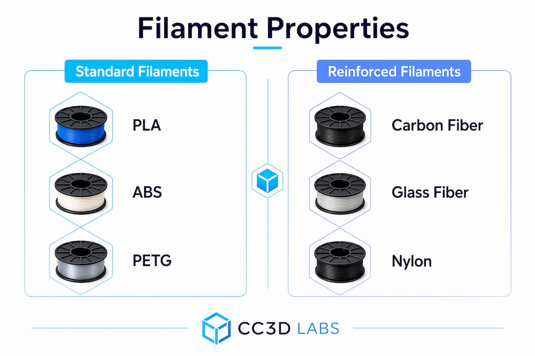
Infographic comparing standard vs reinforced filaments

Software and hardware essentials

CAD software such as Fusion 360, SolidWorks, or FreeCAD handles part geometry. A slicer like PrusaSlicer or Bambu Studio converts the model into printer instructions. Beyond the printer, you need servo motors, M3/M4 fasteners, heat-set brass inserts, and a soldering iron for electronics integration.

How do you design robot parts for strength and function?

Good robot parts design starts with two principles: modularity and load path awareness. Both directly affect how long your parts last and how fast you can fix them when they fail.

Modular robot design with replaceable sub-assemblies improves maintenance speed and iteration rate compared to monolithic designs. When a joint bracket breaks, you reprint that one piece instead of rebuilding the entire arm. This approach also lets you test different geometries for a single joint without redesigning the whole robot.

Selecting infill patterns, wall perimeters of 3 or more, and correct print orientation is critical for structural integrity in functional printed parts. Novice designers consistently underestimate anisotropic stresses, which causes premature part failure under load. Orient parts so the primary load runs parallel to the print layers, not perpendicular to them. For infill, gyroid and honeycomb patterns distribute stress more evenly than rectilinear in parts that experience multi-directional loading. The 3D print infill guide from Cc3dlabs explains pattern selection with specific strength data.

Tolerances and calibration

Dimensional accuracy determines whether your assembly fits together or binds. Print a calibration cube before committing to a full part run. Measure the result with calipers and apply a scaling correction in your slicer or CAD file. For press-fit joints, start with 0.1–0.2mm clearance and adjust based on your printer’s actual output. Calibration prints and measured offsets in CAD or the slicer correct dimensional inaccuracies before they become assembly problems.

Pro Tip: Design cable routing channels and mounting bosses directly into your printed parts. Integrated wiring channels reduce clutter, protect wires from mechanical wear, and make the assembly far easier to service.

What is the step-by-step process for printing and assembling robot parts?

Execution follows a clear sequence. Skipping steps, especially in post-processing, is the most common reason functional parts fail in the field.

  1. Prepare your CAD file. Export as STL or 3MF. Check for non-manifold geometry using Meshmixer or your slicer’s repair tool.
  2. Set slicing parameters. Use 3+ wall perimeters, 30–40% infill for structural parts, and orient the part for maximum load-path alignment.
  3. Print structural components. Enable supports only where geometry requires them. Unnecessary supports add removal time and can damage surface finish.
  4. Remove supports and post-process. Clean support interfaces with flush cutters and needle-nose pliers. For PETG and ABS, annealing and surface treatment relieve internal stresses and improve fatigue resistance.
  5. Install heat-set inserts. Use a soldering iron set to the filament’s softening temperature. Press inserts in straight to avoid angled threads.
  6. Mount servos and electronics. Secure servos with M3 screws into the heat-set inserts. Route wiring through the printed channels before closing any covers.
  7. Test under load before final assembly. Run the joint through its full range of motion with the servo powered. Listen for binding and check for flex in the bracket.

The table below summarizes each phase with realistic time estimates for a single robotic arm joint.

Phase Key action Estimated time
File prep CAD export, repair, slicer setup 30–60 minutes
Printing Structural parts at standard quality 2–6 hours
Post-processing Support removal, annealing, sanding 30–90 minutes
Hardware integration Inserts, servos, wiring 45–90 minutes
Testing Load test, fit check, iteration 30–60 minutes

Pro Tip: Print a single test joint before committing to a full arm print. A 20-minute test part catches fit and clearance problems that would otherwise waste hours of print time.

How do you troubleshoot common issues with 3D-printed robot parts?

Most print and assembly failures have a known cause and a direct fix. The key is diagnosing the right layer of the problem.

  • Warping: Caused by thermal contraction during cooling. Fix with a heated bed, enclosure, or brim. ABS requires an enclosure; PETG rarely warps on a heated glass bed.
  • Under-extrusion: Produces weak, porous layers. Check for a partial clog, reduce print speed by 20%, and verify your extruder steps-per-millimeter calibration.
  • Layer delamination: Usually caused by printing too fast or at too low a temperature. Increase nozzle temperature by 5°C increments until layers bond properly.
  • Dimensional inaccuracy: Parts that are consistently oversized or undersized need a flow rate or XY scaling correction in the slicer. Measure a calibration cube and apply the offset.
  • Stripped heat-set inserts: Caused by under-sized holes or inserts installed at an angle. Redesign the boss with a 0.1mm larger bore and reinstall with a straight press.
  • Joint flex or failure: Increase wall count to 4–5 perimeters, switch to a stiffer filament, or reorient the part so the load runs along the print layers.

For modular designs, the repair strategy is straightforward. Identify the failed sub-assembly, reprint only that component, and swap it in. This is the core advantage of modular design for maintenance. Keeping a small stock of commonly stressed parts, such as wrist brackets and servo mounts, eliminates downtime during testing cycles.

One often-overlooked failure mode is fatigue from vibration. Parts that pass a static load test can still crack after repeated motion cycles. Test every joint through at least 500 full cycles before declaring a design production-ready. If you are working with high-speed or high-load applications, carbon fiber part failure modes are worth understanding before you commit to reinforced filaments.

Key Takeaways

Building custom robot parts with 3D printing requires material selection, design optimization for anisotropic strength, and a modular assembly approach to produce reliable, maintainable robotic components.

Point Details
Material choice drives performance Match filament to load and heat requirements; use PETG or ABS for structural parts.
Print orientation is structural Orient parts so primary loads run parallel to print layers to avoid anisotropic failure.
Modular design speeds iteration Build robots as collections of replaceable sub-assemblies to cut repair and testing time.
Post-processing matters Annealing and surface treatment improve fatigue resistance and dimensional accuracy.
Calibrate before full production Run calibration prints and apply measured offsets before printing final functional parts.

What I’ve learned from printing robot parts that textbooks skip

The biggest mistake I see engineers make is treating 3D printing as a direct substitute for machined metal. It is not. It is a different manufacturing method with its own failure modes, and the ones that catch people off guard are almost always orientation-related. A bracket that looks overbuilt on screen can split cleanly along a layer line under a load that machined aluminum would shrug off. The fix is not always more material. Often it is just a 90-degree rotation in the slicer.

The second lesson is that modular design is not just a maintenance convenience. It is a prototyping accelerator. When you build a robot as a collection of discrete, replaceable joints and brackets, you can run parallel experiments. Print three versions of a wrist joint with different wall counts, test them simultaneously, and have a winner in a day. Monolithic designs force you to reprint the whole assembly every time you change one variable.

My honest recommendation for anyone starting out: spend more time on your first calibration print than you think you need to. Measure every face of the calibration cube, apply the corrections, and print it again. The 45 minutes you invest there will save you hours of failed assemblies later. The functional parts printing guide from Cc3dlabs covers this calibration workflow in depth and is worth reading before your first structural print.

— Justin

Cc3dlabs can print your custom robot parts with precision

Cc3dlabs is a professional 3D printing service based near Philadelphia, specializing in filament-based printing for functional parts, prototypes, and batch production. Engineers and product developers use Cc3dlabs when they need parts that meet tight tolerances without the overhead of running their own print farm.

https://cc3dlabs.com

The team at Cc3dlabs handles everything from CAD modeling and design support to multi-color printing and post-processing. Turnaround times are fast, and the service scales from a single prototype to production-volume orders. Whether you need a one-off joint bracket or a full set of custom robotic components, Cc3dlabs delivers parts ready for assembly. Request a free online estimate directly on the website and get a quote without a sales call.

FAQ

What is the cheapest way to build a 3D-printed robot arm?

A fully 3D-printed robotic arm costs approximately $220 in materials using standard servos and a desktop FDM printer, excluding the printer itself. PLA or PETG filament keeps per-part costs low while still delivering adequate strength for light-duty applications.

Which filament is best for structural robot parts?

PETG is the best starting point for structural 3D printed robot components because it balances strength, heat resistance, and printability. Carbon fiber reinforced filaments offer higher stiffness for demanding applications but require careful print settings to avoid delamination.

How do I make 3D-printed robot parts stronger?

Use 3 or more wall perimeters, orient parts so the primary load runs parallel to the print layers, and choose an infill pattern like gyroid or honeycomb for multi-directional stress. Post-processing with annealing further improves fatigue resistance.

What CAD software works best for robot parts design?

Fusion 360 and SolidWorks are the most widely used CAD tools for custom 3D parts for robotics because both support parametric modeling and direct STL export. FreeCAD is a capable free alternative for engineers on a tight budget.

How tight should tolerances be for 3D-printed robot joints?

Start with 0.1–0.2mm clearance for moving joints and adjust based on calibration prints measured with calipers. Applying a scaling correction in your slicer before printing final parts prevents fit problems during assembly.
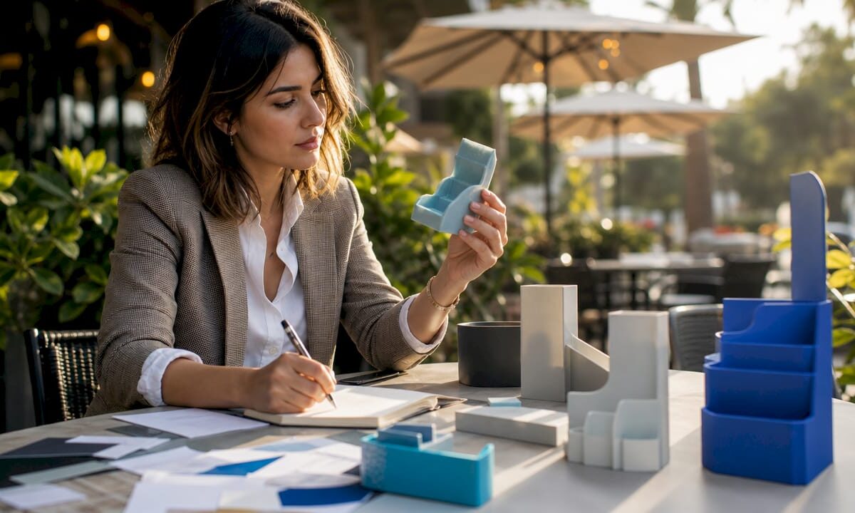
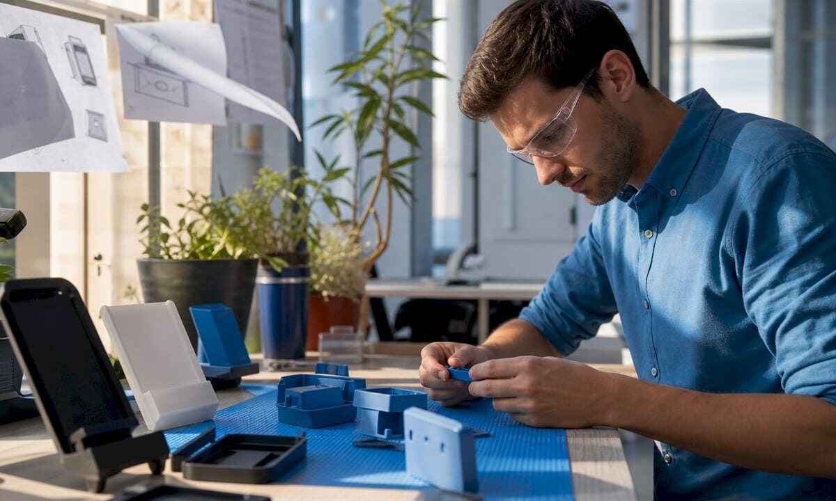
Marketing professional reviewing 3D printed retail displays

Retail Display 3D Print Applications: A Marketer’s Guide


TL;DR:

  • D printing offers custom retail fixtures, signage, and display models that enhance brand visibility and shopper engagement. It enables rapid prototyping, full-color pre-launch models, and material choices suited for different environments, minimizing costs and lead times. Using early-stage design with 3D printing improves efficiency and creates impactful signage, especially through lighting effects and structural reinforcement.

Types of retail display 3D print applications are the specific ways 3D printing technology produces custom in-store fixtures, signage, props, and product models that increase brand visibility and shopper engagement. The industry term for this practice is “retail display additive manufacturing,” though most marketers simply call it 3D printed retail display production. From countertop stands to full-scale trade show props, these applications give retail marketers direct control over design, material, and turnaround time. Cc3dlabs, based near Philadelphia, works with brands across all of these categories, delivering filament-based prints that meet real retail conditions. The sections below cover every major application type, material choice, and lighting technique you need to make informed decisions.

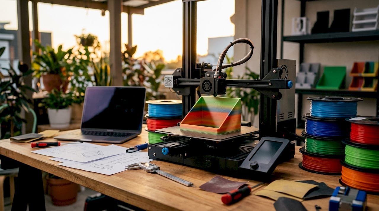
3D printer creating custom retail display fixture

1. Types of retail display 3D print applications marketers use most

3D printed retail displays fall into several clear categories, each serving a different merchandising goal. Knowing which type fits your situation saves time and budget.

  • Channel letters and dimensional signage. These are individual letters or logo shapes mounted to walls, shelves, or facades. They can be front-lit, halo-lit, or side-lit depending on the brand effect you want.
  • Countertop display units. Small printed frames, risers, and product holders that sit at point-of-sale. They are fast to produce and easy to swap between product lines.
  • Floor and endcap displays. Larger freestanding structures with 3D printed panels, brackets, or decorative elements. These often combine printed parts with standard retail fixtures.
  • Oversized product replicas. Giant versions of bottles, boxes, or devices used as window props or trade show centerpieces. Custom 3D printed props protect high-value items from damage or theft in retail and trade show settings.
  • Themed display environments. Printed architectural elements like arches, columns, or branded backdrops that turn a shelf section into an immersive brand space.
  • Shelf talkers and header cards with 3D elements. Flat graphics combined with printed dimensional accents that catch the eye at shelf level.

Pro Tip: Design countertop displays with a flat base plate that is at least 20% wider than the tallest printed element. This prevents tipping without adding weight.

The real role of 3D prints in retail is not to replace every traditional fixture. It is to fill the gaps where standard manufacturing is too slow, too expensive, or too inflexible for short-run or custom needs.

2. Trade show and pre-launch marketing models with full-color printing

Full-color 3D printed models are the fastest way to put a physical product in a buyer’s hands before production starts. Pre-launch 3D models enable marketing teams to conduct studio photography and retailer sell-in months before production units exist, removing product availability bottlenecks for promotional content. That means your catalog, press kit, and retailer presentation can all be ready before the factory ships a single unit.

The advantages of this approach are concrete:

  • Color fidelity. Full-color printing matches Pantone standards, so the model looks identical to the final product under retail lighting conditions.
  • Scale accuracy. Models can be printed at exact product dimensions or at a chosen display scale, giving buyers a true sense of size and proportion.
  • Surface finish. Post-processing techniques like sanding, priming, and clear coating produce a finish that photographs as well as the real product.
  • Speed. A model that would take weeks to source from a factory can be printed and finished in days.

A 2026 industry survey shows full-color marketing models improve retailer sell-in success and shorten product launch cycles significantly. That result matters because compressed launch timelines directly reduce carrying costs and lost sales windows. For influencer outreach, printed models also give creators something physical to photograph and review, which drives more authentic content than digital renders alone.

3. Materials and durability for 3D printed retail displays

Material choice determines whether a printed display survives one trade show or three years of retail floor use. The wrong material costs more in replacements than the right material costs upfront.

  1. PETG (Polyethylene Terephthalate Glycol). PETG is the standard for retail display prototypes because of its toughness, impact resistance, and crack resistance. It handles the bumps of shipping and repeated handling without becoming brittle.
  2. ASA (Acrylonitrile Styrene Acrylate). Best for displays near windows or outdoor retail environments. ASA resists UV degradation and holds color longer than standard ABS.
  3. PLA+ (Enhanced Polylactic Acid). Suitable for short-term indoor displays and trade show models where weight matters more than long-term durability.
  4. Fiberglass-reinforced composites. Large display props often incorporate internal fiberglass reinforcement to prevent deformation and cracking during shipping and repeated handling. This technique adds structural strength without significantly increasing visible bulk.

Pro Tip: Ask your print provider to add 40–60% infill density on any display part that will be handled by shoppers or moved between locations. Higher infill adds strength without changing the external appearance.

Material Best use case Durability level UV resistance
PETG Long-term retail fixtures High Moderate
ASA Window and outdoor displays High High
PLA+ Short-term trade show props Moderate Low
Fiberglass-reinforced Large structural props Very high Depends on coating

For guidance on outdoor display materials, the selection process follows the same logic: match the material to the environment and the expected handling frequency.

4. Lighting and visual effects enabled by 3D printed retail signage

3D printing enables a range of lighting effects that flat-printed signage cannot replicate. Front-lit, halo-lit, side-lit, RGB, and infinity-mirror retail signage each produce a distinct visual result, giving brands a full spectrum of options to fit their positioning.

The choice between lighting styles is a brand decision, not just a technical one:

  • Front-lit letters direct light outward toward the viewer. They deliver maximum visibility in high-traffic, brightly lit retail environments and work well for value-oriented or high-volume brands.
  • Halo-lit letters project light behind the letter onto the wall, creating a soft glow around the shape. Halo-lit signs create an understated, premium aesthetic favored by upscale retailers.
  • Side-lit panels illuminate from the edge, producing a clean, modern look suited to tech and lifestyle brands.
  • RGB programmable signs cycle through colors or respond to triggers like time of day or promotional events. They work best in entertainment retail or experiential pop-up environments.
  • Infinity-mirror effects use layered printed panels with reflective film to create a depth illusion. These are high-impact statement pieces for flagship stores or window installations.

The structural advantage of 3D printing here is direct. Printed letters can be designed with internal channels sized exactly for LED strip widths, which eliminates the hot spots and uneven glow that plague routed foam or cut acrylic alternatives. The result is a cleaner light distribution with less post-production adjustment.

5. How 3D printing accelerates prototyping and iterative display design

Rapid prototyping is the single biggest efficiency gain 3D printing delivers for retail display development. Rapid prototyping with 3D printing allows fast iteration of display parts, greatly accelerating product development cycles and reducing costs associated with molds and tooling. A design change that once required a new mold and a four-week lead time now takes an afternoon.

The practical benefits for retail marketers are specific:

  • Test before committing. Print a single unit of a new countertop display and place it in a test store before ordering 500 units from a traditional manufacturer.
  • Respond to buyer feedback fast. If a retailer requests a different height or a logo repositioned, the CAD file updates in hours and a revised print ships within days.
  • Run parallel design options. Print two or three versions of a display simultaneously and evaluate them side by side in a real store environment.
  • Reduce tooling costs to zero. No injection mold means no $10,000–$50,000 upfront tooling investment for short-run display components.

Low-volume manufacturing with 3D printing is particularly well suited to seasonal retail programs, where display designs change every quarter and volume per design rarely justifies traditional tooling. The 3D modeling process for these display components follows a structured workflow from concept sketch to print-ready file, which keeps revision cycles tight and predictable.

Key takeaways

3D printed retail displays deliver the most value when material, lighting, and prototyping decisions are made together from the start of the design process.

Point Details
Match material to environment Use PETG for long-term indoor fixtures and ASA for window or outdoor displays.
Choose lighting by brand position Front-lit signs maximize visibility; halo-lit signs signal a premium brand identity.
Use full-color models pre-launch Printed models enable retailer sell-in and studio photography before production units exist.
Prototype before scaling Print one unit to test fit, finish, and retailer feedback before committing to volume.
Reinforce large props internally Fiberglass reinforcement prevents deformation in large display props during shipping and repeated use.

Why most retail display programs underuse 3D printing

The brands that get the most from 3D printed retail displays are not the ones with the biggest budgets. They are the ones that bring 3D printing into the process earlier. Most retail marketing teams still treat 3D printing as a last-resort fix when a vendor falls through or a timeline collapses. That is the wrong frame entirely.

The real opportunity is at the front of the project. When you design a display with 3D printing in mind from day one, you get a faster approval cycle, a lower prototype cost, and a finished product that fits the retail environment precisely because you tested it there. I have seen brands spend more on one round of traditional tooling revisions than they would have spent on a full 3D printed prototype program for an entire product line.

The lighting question is where I see the most missed opportunities. Retail marketers often default to front-lit letters because they are familiar. Halo-lit and RGB options are not significantly more expensive to print, but they create a meaningfully different shopper response. The sign that makes someone stop and look is worth more than the sign that simply identifies the brand.

The future of 3D printing in retail is not about replacing all traditional display manufacturing. It is about owning the early stages of every display program, from concept model to in-store test, before any traditional vendor gets involved. That shift alone changes the economics of retail display development.

— Justin

Cc3dlabs custom retail display printing services

Cc3dlabs produces 3D printed retail display components for brands that need fast turnaround, accurate color, and parts built to survive real store conditions.

https://cc3dlabs.com

From countertop display units to large-scale trade show props, Cc3dlabs handles multi-color and multi-material printing with the material expertise to match the right filament to each application. The team also provides CAD modeling support, so you can move from a sketch or reference sample to a print-ready file without sourcing a separate design vendor. Request a free estimate through the 3D printing services page and get a quote specific to your display format, material requirements, and quantity.

FAQ

What are the main types of retail display 3D print applications?

The main types include dimensional channel letter signage, countertop display units, floor and endcap fixtures, oversized product replica props, and themed environmental elements. Each type serves a different merchandising goal and can be produced in materials matched to the display’s expected lifespan and handling conditions.

What material works best for long-term 3D printed retail displays?

PETG is the standard choice for long-term retail display use because of its impact resistance and crack resistance. For displays near windows or in outdoor retail settings, ASA offers better UV stability and color retention over time.

Can 3D printed models replace physical product samples for retailer meetings?

Full-color 3D printed models can replace physical samples for retailer sell-in meetings, studio photography, and press kits. They match Pantone color standards and can be produced months before factory production units are available.

How does 3D printing reduce retail display development costs?

3D printing eliminates tooling costs entirely for short-run display components, which removes the $10,000–$50,000 mold investment required by traditional injection molding. It also shortens revision cycles from weeks to days, reducing the total cost of design iteration.

What lighting options are available for 3D printed retail signage?

3D printed retail signage supports front-lit, halo-lit, side-lit, RGB programmable, and infinity-mirror lighting effects. The right choice depends on brand positioning, ambient store lighting, and whether the sign needs to attract attention or signal a premium identity.

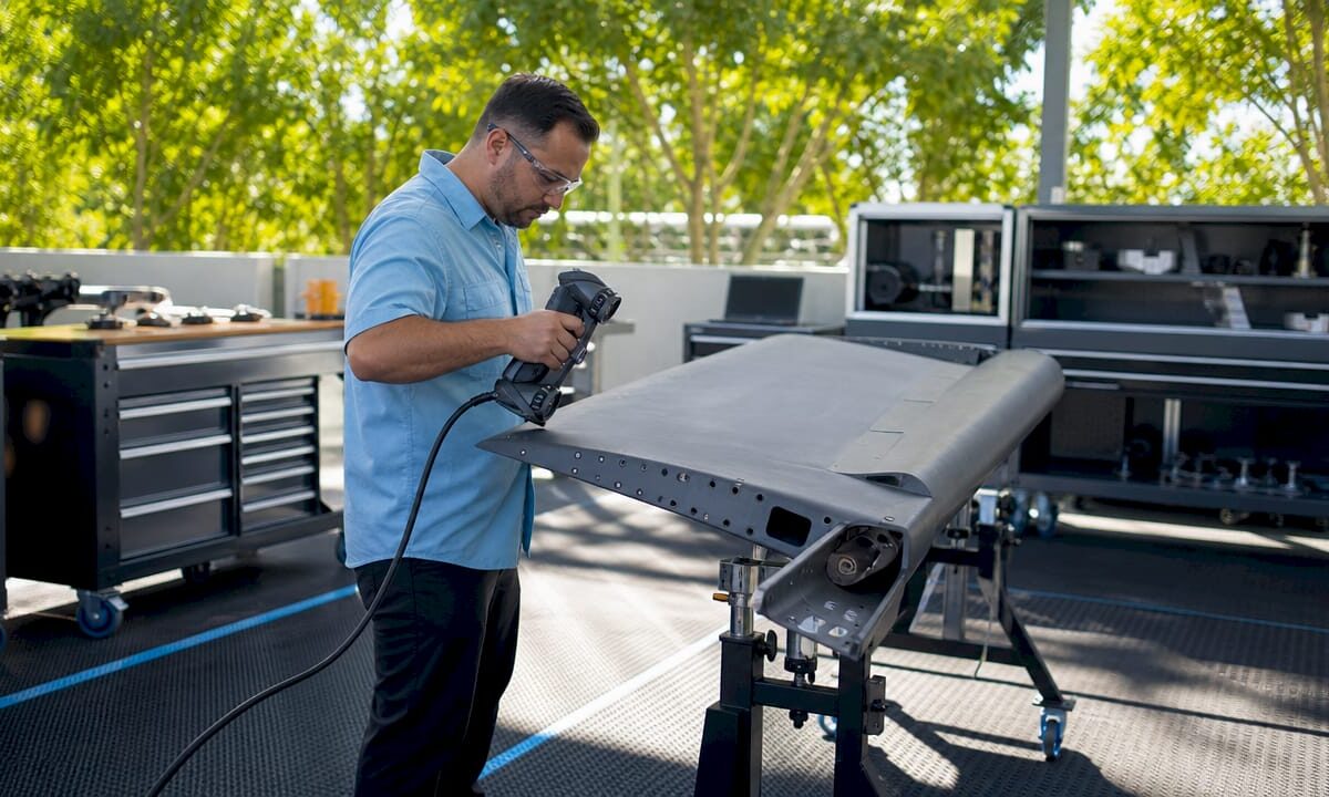
Technician 3D scanning aircraft part in workshop

Types of Industries Using 3D Scan Data: 2026 Guide


TL;DR:

  • D scan data captures precise physical geometry to improve quality, speed, and accuracy across industries. Its adoption enhances workflows in automotive, construction, healthcare, manufacturing, and cultural preservation by enabling real-time measurement and digital integration. Success depends more on software connectivity and post-processing automation than on hardware capabilities.

3D scan data is defined as the digital capture of physical geometry, converting real-world objects into precise point clouds or mesh models used for analysis, design, and production. The types of industries using 3D scan data now span automotive, aerospace, construction, healthcare, manufacturing, and cultural preservation. Each sector adopts 3D scanning, the recognized industry term for this technology, to replace slow manual measurement with full-surface digital capture. The result is faster decisions, fewer errors, and tighter tolerances across every stage of a product’s life.

CAD engineer working with 3D scan data at desk

1. Types of industries using 3D scan data: automotive and aerospace

Automotive and aerospace teams use 3D scanning for quality inspection, reverse engineering, and maintenance, repair, and overhaul (MRO). The shift from traditional coordinate measuring machines (CMMs) to handheld 3D scanners is the single biggest change in industrial metrology over the past decade.

  • Stamped part inspection: 3D scanners capture full surface geometry in minutes. CMMs measure discrete points and miss deformation patterns like springback in sheet metal.
  • Deviation maps: Real-time chromatic deviation maps show exactly where a part drifts from CAD nominal, giving production line operators immediate feedback.
  • Reverse engineering: Engineers scan legacy components with no surviving drawings and reconstruct parametric CAD models for redesign or replacement part production.
  • In-situ aerospace measurement: Aerospace scanning without disassembly captures engine inlet lip geometry at sub-0.03 mm accuracy, delivering certified digital inspection reports without pulling the engine.
  • Timeline compression: Replacing a two-month manual gauge design and build process with minutes-long 3D scanning reduces project timelines by at least 33%.

That 33% reduction is not a rounding estimate. It represents the difference between a gauge shop consuming two months of calendar time and a technician walking the shop floor with a handheld scanner the same afternoon.

Pro Tip: Before scanning stamped metal parts, apply matte reference targets to reflective surfaces. Shiny metal scatters laser light and degrades point cloud density, which forces expensive rescan sessions.

2. Architecture, construction, and facility management

Construction is one of the clearest examples of how 3D scan data benefits an entire project lifecycle, from design coordination through ongoing facility management.

3D LiDAR scanning reduces rework by up to 50% by catching clashes between mechanical, electrical, and plumbing (MEP) systems before installation begins. That number matters because rework is the single largest hidden cost in commercial construction.

How construction teams apply scan data

  1. As-built documentation: Scan the site at each major milestone and compare point clouds against the BIM model to confirm work matches design intent.
  2. Clash detection: Overlay scan data with MEP drawings to find pipe and duct conflicts before crews install anything.
  3. Renovation planning: Scan existing structures to get accurate geometry when original drawings are missing or outdated.
  4. Digital twin creation: Combine successive scans into a living model that facility managers use for space planning, maintenance scheduling, and emergency response.
  5. Quality assurance: Use scan-to-BIM comparison to generate deviation reports that satisfy owner inspection requirements.

The table below shows how scan data changes key construction metrics.

Workflow stage Traditional approach With 3D scan data
As-built verification Manual tape measure and sketches Point cloud vs. BIM comparison in hours
Clash detection 2D drawing review Automated spatial conflict flagging
Rework rate Industry baseline Reduced by up to 50%
Facility handover Paper drawings Accurate digital twin model

For teams managing large facilities, the archival scanning guide from Cc3dlabs covers how to structure scan data for long-term asset management.

3. Healthcare and medical fields

Healthcare uses 3D scanning to capture patient anatomy with a level of accuracy that traditional casting and manual measurement cannot match. Digital workflows replace casting sessions, cutting appointment time and improving fit for prosthetics and orthotics.

  • Prosthetics and orthotics: Clinicians scan residual limbs or affected anatomy, then send the mesh directly to a CAD workstation for socket design. The patient skips the plaster cast entirely.
  • Surgical planning: Surgeons import patient-specific scan data into simulation software to rehearse complex procedures on a digital replica before entering the operating room.
  • Dental and orthodontic labs: Intraoral scanners produce digital impressions that replace physical molds. Labs receive files, not trays of alginate, and produce crowns, aligners, and retainers from the digital model.
  • Bioprinting research: Scan data of tissue structures feeds into bio-printing workflows for research into custom implants and scaffolding.

Pro Tip: For prosthetic socket design, scan the contralateral limb as a symmetry reference. Designers use it to mirror geometry and reduce the number of fitting iterations the patient needs.

The speed advantage in healthcare is real. A scan session takes minutes. A traditional casting session takes 30 minutes or more, requires drying time, and still produces a static model that cannot be digitally modified.

4. Industrial manufacturing and reverse engineering

Manufacturing is where 3D scan data has its deepest roots and its most measurable financial impact. The core shift is from sampling-based CMM inspection to full surface geometry capture that reveals deformation patterns no point measurement can detect.

  • Reverse engineering: Scan a physical part, align the point cloud in CAD software, and reconstruct a parametric model. This is the standard path for legacy tooling with no surviving drawings.
  • Quality control integration: Real-time integrated scanning generates deviation maps on the production line, replacing end-of-shift inspection reports with live feedback.
  • PLM and quality system integration: The true value of 3D scanning comes from connecting scan data to PLM and CAD software, forming a digital ecosystem rather than treating the scanner as a standalone tool.
  • Post-processing management: Data alignment, mesh cleanup, and parametric CAD conversion can equal scanning time without automation. Teams that underestimate this step lose the efficiency gains they expected.

Transitioning to real-time integrated metrology reduces inspection costs by over 50% in high-precision manufacturing. Traditional inspection can account for more than half of a qualified metal component’s total production cost. That figure alone justifies the capital investment for most production managers.

For a practical breakdown of how to structure scan-to-CAD workflows, the scan to CAD workflow guide at Cc3dlabs covers the full process from raw point cloud to production-ready file. Teams dealing with industrial measurement challenges will also find that real-time scan integration directly improves process control at the machine level.

5. Cultural heritage, entertainment, and emerging fields

3D scanning extends well beyond factories and hospitals. Cultural heritage and entertainment industries use scan data to document, preserve, and recreate physical reality at a level of detail that photography cannot achieve.

  • Historic landmark preservation: Scan teams capture full building geometry before restoration work begins. If a structure is damaged, the scan record supports accurate reconstruction.
  • Museum archiving: Institutions scan artifacts to create digital records for research access, reducing physical handling of fragile objects.
  • Art restoration: Conservators use scan data to document surface condition before treatment and verify results afterward.
  • VFX and gaming: Studios scan actors, props, and environments to create photorealistic digital assets for film and game production. The scan replaces weeks of manual modeling.
  • VR and AR content: Scan-based environments give users accurate spatial context that hand-modeled scenes cannot replicate.
  • Biotech and emerging applications: Researchers scan anatomical structures to inform bio-printing and custom implant design, pushing 3D scan data into territory that did not exist as a commercial application five years ago.

The entertainment industry’s adoption of 3D scanning is a useful signal for other sectors. When a technology becomes standard practice in a field as cost-sensitive as film production, the hardware and software costs have dropped to a point where most professional organizations can justify the investment.

Key takeaways

3D scan data delivers the greatest value when integrated directly into existing CAD, PLM, and quality management systems rather than used as a standalone measurement tool.

Point Details
Automotive and aerospace lead adoption Handheld scanning cuts project timelines by at least 33% over traditional manual gauging.
Construction rework drops sharply LiDAR-based scan-to-BIM comparison reduces rework by up to 50% on commercial projects.
Healthcare replaces physical casting Digital anatomy capture speeds prosthetic design and eliminates plaster casting sessions.
Manufacturing gains real-time control Integrated scanning cuts inspection costs by over 50% by replacing batch post-process reports.
Software integration drives ROI Connecting scan data to PLM and CAD systems creates a digital ecosystem that multiplies scanner value.

What I’ve learned about 3D scan data adoption across industries

The conversation about 3D scanning almost always starts with hardware. Which scanner has the best resolution? Which one is fastest? That is the wrong question, and I have seen it derail more than a few adoption projects.

The hardware is good enough. It has been good enough for years. What separates teams that get real results from teams that buy expensive equipment and underuse it is software integration. If your scan data cannot talk to your CAD system, your PLM platform, or your quality management workflow, you have a very expensive ruler.

The second thing professionals consistently underestimate is post-processing time. Scanning a part takes minutes. Aligning the point cloud, cleaning the mesh, and converting it to a usable CAD format can take just as long without the right automation tools in place. Plan for that time before you promise your stakeholders a turnaround.

The trend I find most significant right now is real-time integrated metrology. Moving inspection from the end of a production run to the machine itself changes the economics of quality control entirely. You stop making bad parts instead of sorting them out afterward. That shift is what will push 3D scanning from a specialty tool to a standard production asset across every sector covered here.

My advice to any decision-maker evaluating 3D scanning: audit your data ecosystem first. Know exactly where scan outputs will live, who will access them, and how they connect to downstream decisions. The scanner is the easy part.

— Justin

Cc3dlabs supports your 3D scanning and production workflow

Cc3dlabs operates a professional 3D scanning lab near Philadelphia that handles professional handheld 3D scanning (accuracy to ~0.1 mm) for parts, prototypes, and complex assemblies. The lab’s outputs connect directly to CAD modeling and filament-based 3D printing, so your team moves from physical object to production-ready file without switching vendors.

https://cc3dlabs.com

Whether you need a single prototype scanned and printed or a batch production run built from scan-derived CAD data, Cc3dlabs covers the full workflow. The 3D printing services page lists current capabilities, turnaround options, and how to request a free estimate. Local pickup is available, and shipping serves clients across the country.

FAQ

What industries use 3D scan data most extensively?

Automotive, aerospace, construction, healthcare, and industrial manufacturing are the primary sectors. Each uses 3D scanning for quality control, reverse engineering, or documentation workflows that require full-surface geometry capture.

How does 3D scanning reduce construction rework?

LiDAR scanning compares physical site conditions against BIM models in real time, catching clashes and deviations before installation. This process reduces rework by up to 50% on commercial construction projects.

What is the difference between CMM inspection and 3D scanning?

CMMs measure discrete points on a surface. 3D scanning captures millions of points per second across the full surface, revealing deformation patterns and deviations that point measurements miss entirely.

How does healthcare benefit from 3D scan data?

Clinicians use scan data to design prosthetics, plan surgeries, and produce dental restorations without physical casting. Digital workflows are faster, more accurate, and produce files that labs can modify without a new patient appointment.

What should teams plan for before adopting 3D scanning?

Plan for post-processing time alongside scanning time. Data alignment, mesh cleanup, and CAD conversion require dedicated software and trained staff. Teams that skip this planning consistently underdeliver on the efficiency gains they projected.

Engineer inspecting 3D printed POS components

Types of 3D Printed POS Components: Business Guide


TL;DR:

  • Point-of-sale 3D printed components include displays, tactile input modules, protective enclosures, and immersive display assemblies. These parts are customizable, cost-effective for small batches, and improve retail functionality and customer engagement. Proper material selection and design testing are essential to ensure durability and long-term performance.

Types of point-of-sale 3D printed components are specialized hardware elements designed to improve retail system function and customer engagement through custom manufacturing. The industry term for this category is “additive-manufactured POS hardware,” though the practical shorthand used across retail and manufacturing circles is “3D printed POS hardware.” These components span electromechanical displays, tactile input modules, protective enclosures, and immersive display assemblies. Techniques like 6-axis robotic conformal printing and multi-material filament deposition now make it possible to produce parts that were previously impossible or prohibitively expensive to fabricate at small scale.

1. What are the types of point-of-sale 3D printed components?

The core categories of 3D printed POS hardware break down by function: display components, tactile and input hardware, structural and protective parts, and immersive display assemblies. Each category serves a distinct operational role. Choosing the wrong category for a given need wastes budget and creates maintenance problems. Understanding each type before committing to production is the most direct path to a functional, cost-effective POS upgrade.

  • Electromechanical display components: Split-flap panels, seven-segment modules, and embedded-circuit display frames
  • Tactile and input hardware: Custom keypads, card reader mounts, ergonomic housings, and physical button arrays
  • Structural and protective parts: Enclosures, brackets, covers, and cable management frames
  • Immersive display assemblies: Glasses-free stereoscopic frames, light-field display mounts, and holographic projection housings

Each category requires different materials, printing processes, and post-processing steps. The sections below cover each in depth.

2. Electromechanical 3D printed display components

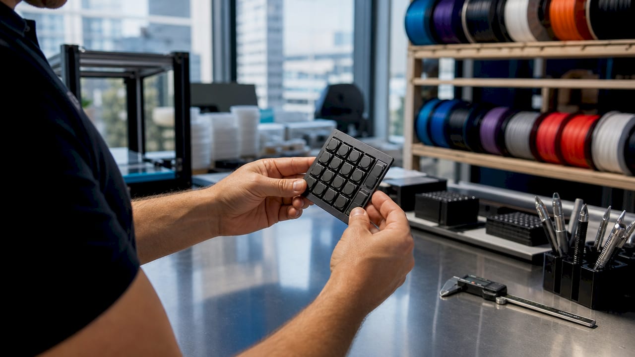
Close-up of hands holding POS 3D printed button

Electromechanical displays are the most technically demanding category of 3D printed POS hardware. Split-flap displays consume electricity only during state changes, making them highly energy-efficient for retail environments where displays run continuously. That efficiency translates directly to lower operating costs over a multi-year deployment.

Suction-driven seven-segment displays use vacuum-actuated membranes to flip segments, but achieving an airtight seal in a 3D printed body requires multiple fasteners and specialized post-processing. The sealing challenge is the primary maintenance risk in this category. Businesses that deploy these displays should plan for periodic seal inspection as part of routine POS maintenance.

Robotic arm-assisted conformal printing using 6-DOF arms expands the printable workspace, allowing circuitry to be embedded directly onto curved or nonplanar surfaces. This reduces assembly complexity and enables multilayer electronic displays that integrate directly into a POS terminal body. The result is a display that looks built-in rather than bolted on.

Pros of electromechanical 3D printed displays:

  • Low power draw during static display states
  • High tactile novelty that draws customer attention
  • Fully customizable character sets and segment layouts
  • Printable in small batches without tooling costs

Cons to plan for:

  • Mechanical parts wear over time and require replacement
  • Pneumatic sealing demands precise assembly
  • Motor positioning tolerances must be tight to avoid misalignment

Pro Tip: When designing split-flap modules, specify motor shaft tolerances to within 0.1mm in your CAD file. Loose tolerances cause character misalignment under repeated cycling, which is the leading cause of field failures in this component type.

3. How 3D printed tactile and functional hardware improves POS usability

Tactile hardware is the category most businesses encounter first when exploring 3D printing for retail systems. Custom keypads, card reader mounts, and physical button arrays can be sized, textured, and laid out to match a specific workflow. A keypad designed for a high-volume quick-service counter looks and feels different from one designed for a jewelry boutique checkout.

Rapid prototyping and iterative design reduce development time and allow tailored customer interaction points. A business can print three keypad layouts on a Tuesday, test them with staff on Wednesday, and have a final design in production by Friday. That cycle is impossible with injection molding.

Material selection directly affects durability and feel. Common materials include standard PLA for low-wear prototypes, PETG for moderate-impact parts, and nylon or TPU for high-use tactile surfaces that need flex and grip. Multi-material printing allows a single keypad to combine a rigid structural base with a soft-touch button surface.

Key tactile hardware applications:

  • Custom-sized keypads for non-standard POS layouts
  • Card reader mounts that angle the reader toward the customer
  • Ergonomic stylus holders and signature pad frames
  • Physical button guards that prevent accidental input
  • Cable routing clips integrated into the terminal housing

4. What role do protective and structural 3D printed components play in POS systems?

Protective components are the unsung category of custom POS components. They do not interact with customers directly, but they determine whether expensive POS electronics survive a busy retail environment. A custom-fit enclosure for a proprietary payment terminal protects against spills, drops, and dust without requiring the retailer to buy a new device when the original housing cracks.

Manufacturing-grade 3D printing processes improve mechanical properties and dimensional accuracy needed for POS devices operating under high-use conditions. Parts printed to manufacturing-grade standards hold tighter tolerances and resist deformation under sustained load. That matters for brackets and mounts that carry the weight of a display or scanner all day.

Material choices for protective parts prioritize impact resistance, heat dissipation, and aesthetic finish. ASA and ABS handle UV exposure and moderate heat better than PLA, making them the right choice for terminals near windows or under heat lamps. Carbon-fiber-filled filaments add stiffness without significant weight gain, which is useful for wall-mounted display brackets.

Pro Tip: For enclosures that house electronics generating heat, design ventilation channels directly into the CAD model rather than adding them as afterthoughts. Channels integrated into the print geometry are stronger and more consistent than drilled holes added post-print.

Structural component types by function:

  • Enclosures: Full or partial housings for tablets, card readers, and receipt printers
  • Brackets and mounts: Wall, counter, and pole mounts for displays and scanners
  • Cable management frames: Clips, channels, and routing guides that keep wiring organized
  • Protective covers: Dust and splash guards for ports and screens during non-business hours

5. Which advanced 3D printed display technologies are emerging for immersive POS?

Glasses-free stereoscopic displays create immersive multi-user 3D experiences at POS without auxiliary devices, which changes how retailers can present products at the point of sale. A customer standing in front of a light-field display sees a floating 3D product image without wearing anything. That level of engagement is not achievable with a standard flat screen.

The physical frames, mounts, and housings for these displays are where 3D printing enters the picture. Holographic projection housings require precise optical alignment, and custom-printed frames hold lenses and mirrors at exact angles that off-the-shelf enclosures cannot match. 3D printing makes small-batch production of these specialized frames economically viable.

Display type Principle POS advantage Key challenge
Holographic 3D Laser interference patterns High visual impact, no glasses needed High production cost
Optical illusion stereoscopic Lenticular lens arrays Works at distance, multi-user Limited viewing angle
Floating 3D (Pepper’s Ghost) Angled mirror reflection Low cost, high drama Requires dark surround
Light-field 3D Dense pixel arrays True depth perception High compute demand

Adoption of glasses-free 3D display technologies is set to redefine retail exhibition by enabling multi-user immersive experiences without glasses or headsets. The physical infrastructure for these displays, including printed mounts and alignment frames, is already within reach for businesses working with a capable 3D printing provider.

6. How to choose the right type of 3D printed POS component for your business

The right component type depends on three factors: customer-facing versus back-of-house function, expected daily use volume, and budget for ongoing maintenance. A high-traffic grocery checkout needs impact-resistant structural parts above all else. A boutique retailer benefits more from a visually striking electromechanical display or a custom tactile keypad.

On-demand 3D printing reduces inventory stockpiling by enabling replacement part production when needed. Businesses that maintain a digital file library of their printed components can reorder a cracked enclosure or worn keypad within days, not weeks. That operational advantage compounds over time.

Decision framework by business type:

  • High-volume retail (grocery, pharmacy): Prioritize structural enclosures and durable tactile hardware in PETG or nylon
  • Boutique or experiential retail: Invest in electromechanical displays or immersive display frames for customer engagement
  • Food service: Focus on splash-resistant enclosures with integrated cable management
  • Exhibition or pop-up retail: Use lightweight printed mounts for glasses-free displays and modular structural frames

Production considerations matter as much as design. Filament-based FDM printing suits structural and tactile parts. Resin-based SLA printing delivers the surface finish needed for optical components in display housings. Turnaround time for a single custom part runs from one to three business days at a professional print shop, while batch orders of 20 or more units typically require five to ten business days depending on complexity.

Key takeaways

The most effective 3D printed POS hardware strategy combines electromechanical displays for engagement, durable tactile modules for usability, and precision-fit structural parts for long-term reliability.

Point Details
Match component type to function Electromechanical displays drive engagement; structural parts protect electronics.
Material choice determines lifespan PETG and nylon outperform PLA in high-use POS environments.
On-demand printing cuts downtime Digital file libraries let businesses reorder replacement parts within days.
Tolerances define performance Motor and seal tolerances under 0.1mm prevent the most common field failures.
Immersive displays need custom frames Glasses-free 3D displays require precision-printed mounts to maintain optical alignment.

What I’ve learned from watching businesses get POS hardware wrong

Most businesses that struggle with 3D printed POS components make the same mistake: they treat the print as the finished product. A printed enclosure that fits perfectly on day one can warp, crack, or loosen within six months if the material was chosen for cost rather than environment. I’ve seen PETG enclosures near heat lamps soften and deform, and PLA keypads crack under the pressure of a busy lunch rush.

The businesses that get it right treat the first print as a prototype, even when they intend to deploy it immediately. They test it under real conditions for two weeks, note every failure point, and then revise the CAD file before ordering a full batch. That two-week investment prevents months of field problems.

Precision matters more than most buyers expect. The difference between a split-flap display that runs reliably for two years and one that jams after three months is often a 0.2mm tolerance error in the motor mount. Working with a provider that holds manufacturing-grade tolerances is not a premium option. It is the baseline requirement for any electromechanical component.

My strongest advice: do not separate the design phase from the production phase. The best outcomes come from working with a 3D printing provider that can give feedback on your CAD file before printing starts. A provider that only takes files and prints them will miss problems that an experienced eye catches in five minutes.

— Justin

Cc3dlabs custom 3D printed POS components

Businesses that need custom POS hardware built to real operational standards work with Cc3dlabs, a professional 3D printing service near Philadelphia specializing in filament-based printing, multi-material production, and professional handheld 3D scanning (accuracy to ~0.1 mm).

https://cc3dlabs.com

Cc3dlabs produces functional POS parts from prototypes to production batches, including electromechanical display frames, ergonomic tactile modules, and impact-resistant enclosures. Their custom 3D printing services cover material selection, CAD review, and quality inspection before any part ships. For businesses that need to scan an existing terminal before designing a custom enclosure, Cc3dlabs also offers 3D scanning to capture exact geometry. Request a free estimate directly on their website, with options for local pickup near Philadelphia or shipping anywhere in the country.

FAQ

What are the main types of 3D printed POS components?

The main types are electromechanical display components, tactile and input hardware, structural and protective enclosures, and immersive display frames. Each type serves a distinct function in a point-of-sale system.

Are 3D printed POS components durable enough for daily retail use?

Yes, when printed in the right material. PETG, nylon, and ASA filaments produce parts that withstand high-use retail environments, while PLA is better suited for prototyping than long-term deployment.

How long does it take to produce a custom POS component?

A single custom part typically takes one to three business days at a professional print shop — industry-typical ranges; CC 3D Labs confirms actual turnaround with your quote, after a test print of the part. Batch orders of 20 or more units generally require five to ten business days depending on complexity and material.

What is a split-flap display and why is it used at POS?

A split-flap display is an electromechanical panel that flips printed segments to show characters or numbers. It draws power only during state changes, making it energy-efficient and visually distinctive for customer-facing retail applications.

Can 3D printing replace injection molding for POS hardware?

3D printing is the better choice for custom, low-to-medium volume POS components because it eliminates tooling costs and supports rapid design iteration. Injection molding remains more cost-effective only at very high volumes where per-unit cost matters more than design flexibility.