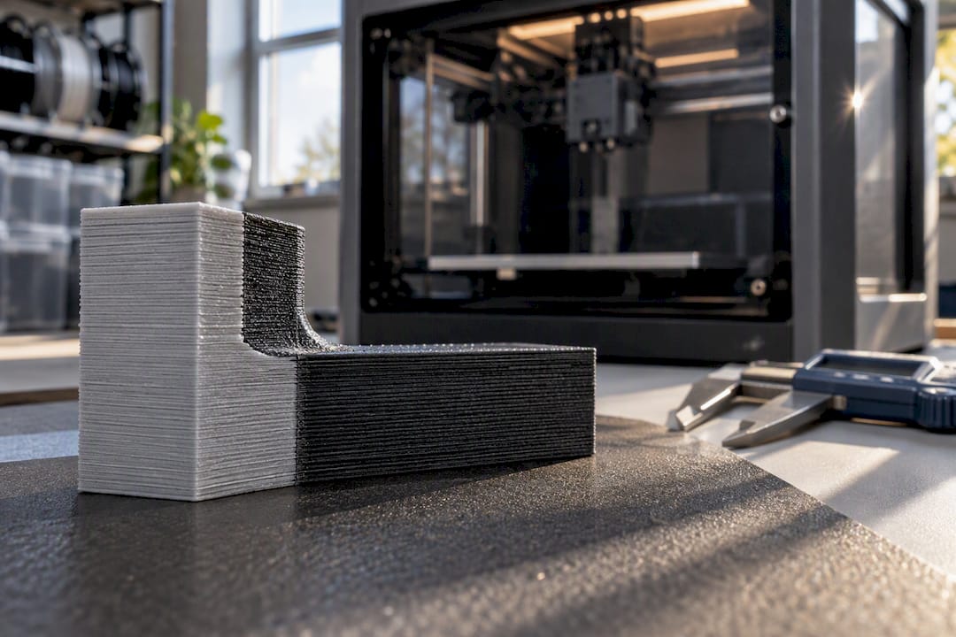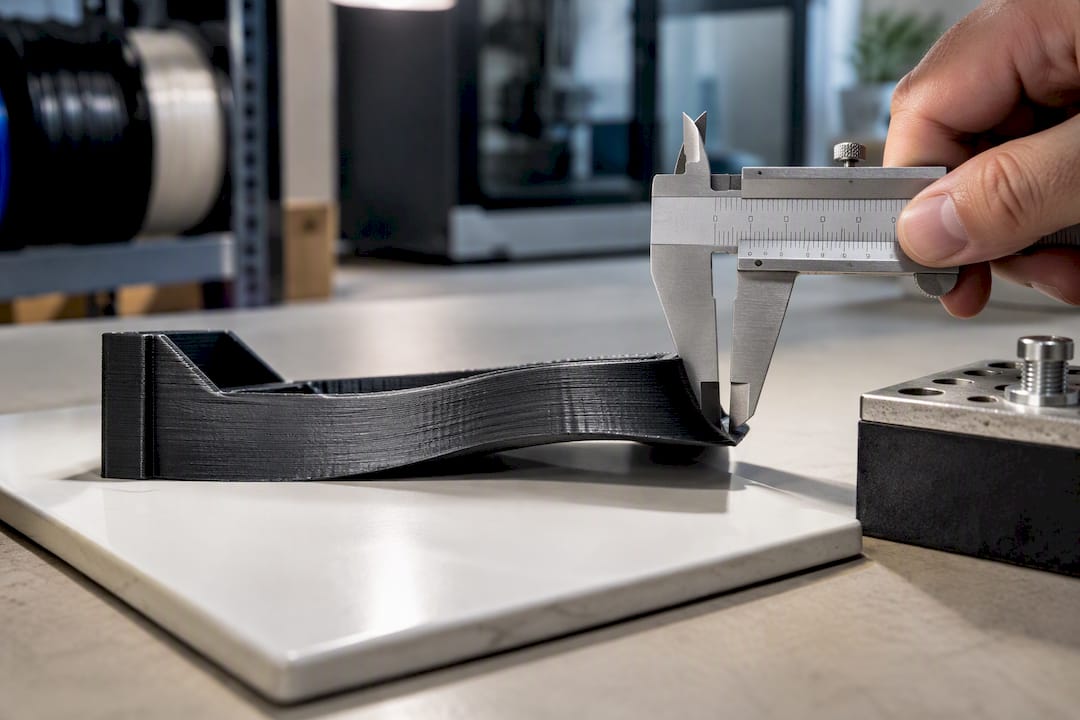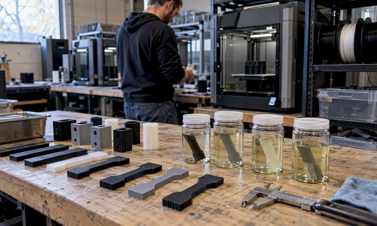
Engineer inspecting 3D printed part with calipers

Print Tolerance Standards Explained for Engineers


TL;DR:

  • Print tolerance standards define the acceptable dimensional deviations in 3D printed parts, ensuring proper fit and function. Achieving the correct tolerances depends on machine accuracy, material shrinkage, and thoughtful design to prevent errors and meet industry standards. Validating these tolerances through test prints and systematic measurement is essential for reliable, high-quality production.

Print tolerance standards define the allowable dimensional deviation in a 3D printed part so it fits and functions as designed. Get them wrong, and a press fit becomes a loose rattle or an immovable bond. Get them right, and assemblies snap together on the first try. Explaining print tolerance standards is not just an academic exercise. It is the difference between a prototype that validates your design and one that wastes a full production run. This guide covers fit types, material shrinkage, printer accuracy, and testing methods so you can build parts that meet spec every time.

What are print tolerance standards in 3D printing?

Print tolerance standards specify the maximum and minimum acceptable dimensions for a printed part relative to its nominal design size. The industry term for this concept is “dimensional tolerance,” and it maps directly to the ISO 286 system used in traditional machining. In 3D printing, tolerances are harder to hold because every variable, from filament diameter to bed temperature, shifts the final dimension.

Hands measuring 3D printed gear with caliper

Tolerance depends heavily on use case, fit type, printer model, and material. That means a single tolerance value cannot cover every situation. Engineers must define tolerances per feature, per material, and per machine class.

The practical consequence is significant. A part designed with a 0.2 mm clearance on a budget printer may come out with zero clearance because that machine holds only ±0.3 to ±0.5 mm on a good day. Mid-range machines tighten that to ±0.1–0.3 mm, and precision machines reach ±0.05–0.15 mm. Knowing your machine class before you set tolerances in CAD is the first rule of print quality standards.

What are the typical tolerance values for different fit types?

Fit type determines how much clearance or interference you build into mating parts. The three categories engineers use most are press fit, sliding fit, and loose fit.

Fit type Clearance or interference Typical use
Press fit -0.1 to -0.2 mm interference Permanent joints, bearing seats
Sliding fit 0.2–0.4 mm clearance Drawers, rails, moving assemblies
Loose fit 0.5–1.0 mm clearance Pins, alignment pegs, quick-swap parts

Infographic showing ranked print tolerance types and factors

Industry standards recommend 0.1 mm clearance for tight connectors, 0.2–0.4 mm for sliding parts, and 0.5–1.0 mm for loose pins. These values assume a mid-range printer and PLA or PETG. Material choice shifts the numbers considerably.

Press fit interference also varies by material. PLA requires -0.15 to -0.25 mm, PETG needs -0.20 to -0.30 mm, Nylon runs -0.30 to -0.40 mm, and TPU demands -0.40 to -0.60 mm because of its flexibility. A Nylon press fit designed with PLA values will pull apart under load. Always match interference values to the material you are actually printing.

Clearance for peg and hole features ranges from 0.2 mm per side for alignment to 0.4 mm or more for free movement. These are per-side values, so a 10 mm pin in a 10.4 mm hole has 0.2 mm clearance on each side. That distinction trips up many designers who apply total gap instead of per-side gap.

Pro Tip: Build a small test coupon with three or four fit types at different clearances before committing to a full print run. Ten minutes of test printing saves hours of rework.

How do material properties and shrinkage influence 3D print tolerances?

Shrinkage is the single most underestimated variable in understanding print tolerances. Every thermoplastic contracts as it cools, and that contraction pulls dimensions below the nominal CAD value.

The shrinkage rates by material are:

  • PLA: 0.3–0.5% shrinkage. Pre-scale models by 100.3–100.5% to compensate.
  • ABS and ASA: 0.8–1.2% shrinkage. These materials also warp without an enclosed chamber, which adds unpredictable dimensional error beyond simple scaling.
  • Nylon: 1.0–2.5% shrinkage. Pre-scaling by 100.5–102.5% is required, and even then, ambient humidity affects the final dimension because Nylon absorbs moisture.
  • TPU: Low shrinkage but high elasticity means interference values must account for the material springing back after assembly.
  • PETG: Moderate shrinkage, typically 0.4–0.6%, with better layer adhesion than PLA and less warping than ABS.

Pre-scaling compensates for uniform shrinkage, but shrinkage is rarely uniform. Tall parts shrink more in Z than in X or Y. Wide flat parts warp at the edges. The practical fix is to print a calibration cube, measure all three axes with calipers, and apply axis-specific scale factors in your slicer. A single global scale factor is a starting point, not a solution. Designers working with advanced filament materials should treat shrinkage compensation as a per-material, per-geometry workflow step rather than a one-time setting.

What printer and design factors affect adherence to print tolerance standards?

Printer accuracy sets the ceiling for what tolerances you can hold. Design choices determine whether you reach that ceiling or fall short of it.

Four factors control most of the dimensional error in filament-based printing:

  1. Calibration state. An uncalibrated extruder over-extrudes, which thickens walls and closes clearances. E-steps, flow rate, and linear advance settings all affect final dimensions. Recalibrate after every nozzle change or filament switch.

  2. Print orientation. Features printed in the XY plane hold tighter tolerances than features built up in Z. Layer lines in Z create stair-stepping on curved surfaces, which adds effective dimensional error. Orient critical mating surfaces to lie in the XY plane whenever possible.

  3. Elephant foot effect. The first layer spreads under nozzle pressure and bed adhesion, adding 0.2–0.5 mm to bottom dimensions. That extra material ruins press fits and prevents flat mating surfaces from seating correctly. Chamfering the base by 0.5 mm offsets this effect without requiring slicer compensation.

  4. Horizontal holes. Horizontal holes print undersized because filament sags across the unsupported span. Adding 0.2 mm to the hole diameter in CAD, or reorienting the part so the hole axis is vertical, corrects this consistently.

Pro Tip: Add a 0.5 mm chamfer to every base edge as a default in your CAD template. Experienced designers pre-chamfer bases to offset first-layer over-extrusion before the problem ever reaches the printer.

Design strategy matters as much as printer settings. Avoid sharp internal corners on mating features because filament rounds them, reducing effective clearance. Use drafting standards in 3D modeling to add draft angles on vertical walls, which improves dimensional consistency across the full height of a part. Split long mating surfaces into shorter segments to reduce the cumulative effect of warping on fit.

How can manufacturers and engineers test and validate print tolerance compliance?

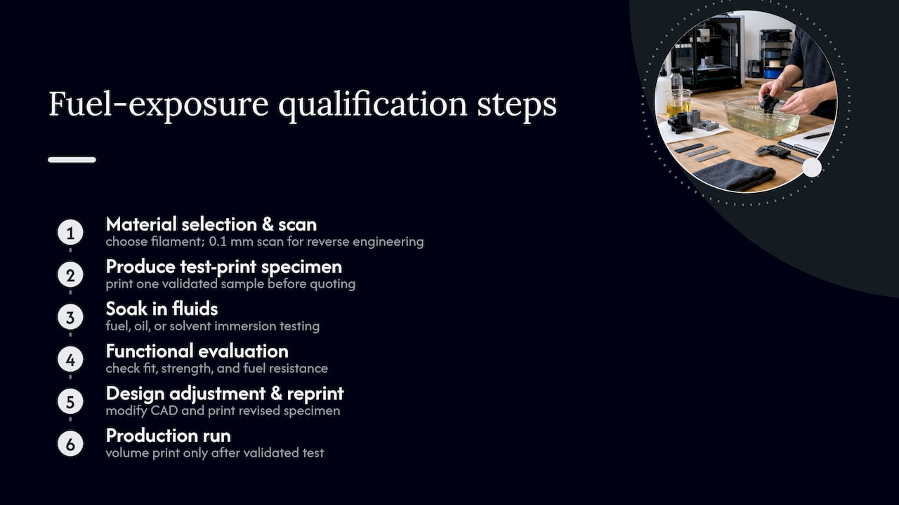
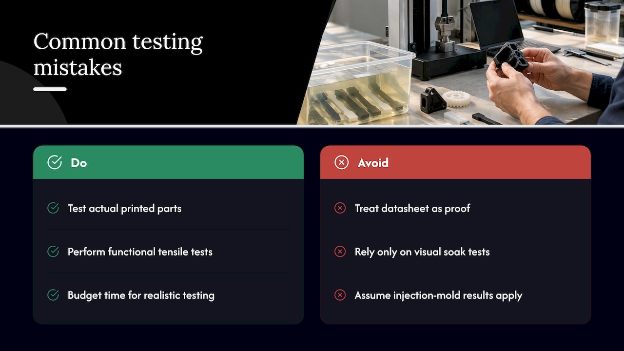
Testing is the only way to confirm that your tolerance strategy works on a specific printer with a specific material. Assumptions based on spec sheets fail in practice because real-world conditions always differ from controlled lab conditions.

A systematic validation workflow includes these steps:

  • Print a tolerance cube. A 20 mm cube with labeled walls is the baseline. Measure all six faces with digital calipers. Any deviation from 20.00 mm tells you your scale factor and flow rate need adjustment before you print functional parts.

  • Use a pin and slot test model. Print a series of pins and matching slots with clearances ranging from 0.1 mm to 0.5 mm in 0.1 mm steps. The smallest clearance that allows free movement is your sliding fit baseline for that printer and material combination.

  • Apply go/no-go gauges. For production runs, go/no-go gauges are faster than calipers. A go gauge must pass through the feature; a no-go gauge must not. This binary check catches out-of-tolerance parts in seconds without requiring measurement skill.

  • Document results per material and printer. Calibration test prints with dimensional checks identify necessary tolerance adjustments for a given printer and material. Keep a log. When you switch filament brands or update firmware, rerun the test suite and compare against your baseline.

  • Iterate in CAD, not in post-processing. Sanding and drilling to fix tolerance errors is a one-off fix that does not scale. Adjust the CAD model, reprint, and retest. Three iterations typically converge on a working tolerance for a new material and printer combination.

For engineers managing part validation in 3D printing, this workflow should be formalized as a standard operating procedure before any part moves from prototype to batch production.

Key takeaways

Print tolerance standards require matching fit type, material shrinkage, and printer accuracy before a single layer is deposited, because correcting dimensional errors after printing costs more than designing them out.

Point Details
Fit type sets the baseline Press fits need -0.1 to -0.2 mm interference; sliding fits need 0.2–0.4 mm clearance.
Material shrinkage shifts dimensions PLA shrinks 0.3–0.5%; Nylon shrinks up to 2.5% and requires axis-specific scale compensation.
Printer class limits achievable tolerance Budget machines hold ±0.3–0.5 mm; precision machines reach ±0.05–0.15 mm.
Design choices prevent common errors Chamfer bases by 0.5 mm and add 0.2 mm to horizontal hole diameters to offset known print artifacts.
Test before committing to production Pin and slot test prints plus go/no-go gauges validate tolerances faster than caliper-only inspection.

Why I think most engineers underestimate tolerance testing

Most engineers I work with treat tolerance as a CAD problem. They set a clearance value, send the file, and expect the printer to deliver. The printer does not care about your CAD intent. It responds to calibration state, ambient temperature, filament moisture, and a dozen other variables that shift from one print session to the next.

The engineers who consistently hit tight tolerances share one habit: they test systematically and document everything. They know their printer’s actual accuracy range, not the spec sheet range. They know how their preferred Nylon brand behaves after sitting in a humid shop overnight versus a dry box. That knowledge comes only from running test prints and keeping records.

The other thing I have seen change outcomes is designer-engineer collaboration at the tolerance-setting stage, not after the first failed prototype. When the person who understands the assembly function talks to the person who understands the printer before the CAD is finalized, the first print usually fits. When those conversations happen after a failed batch, you are paying twice.

Emerging technologies like in-process dimensional monitoring and closed-loop slicer feedback are starting to reduce the gap between intended and actual dimensions. But in 2026, systematic testing and documentation remain the most reliable path to reliable 3D prototyping that holds tolerance across a full production run.

— Justin

Cc3dlabs precision printing for functional parts

Cc3dlabs operates near Philadelphia and specializes in filament-based 3D printing for functional prototypes, production parts, and batch orders where dimensional accuracy is not optional.

https://cc3dlabs.com

Every order at Cc3dlabs starts with a review of fit requirements, material selection, and tolerance targets before a file goes to the printer. The team supports press fits, sliding assemblies, and loose-fit components across PLA, PETG, Nylon, TPU, and specialty filaments. For engineers who need parts that meet spec on the first run, Cc3dlabs offers professional 3D printing services with design support, free online estimates, and local pickup or shipping. If your current workflow is producing out-of-tolerance parts, the right starting point is a conversation about material, machine, and fit requirements.

FAQ

What is a standard tolerance for 3D printed parts?

Standard tolerances range from ±0.3–0.5 mm on budget printers to ±0.05–0.15 mm on precision machines. The right value depends on fit type, material, and the specific printer being used.

How much clearance should I add for a sliding fit?

A sliding fit requires 0.2–0.4 mm of clearance between mating surfaces. Start at 0.3 mm for a mid-range printer with PLA or PETG, then adjust based on test print results.

Why do my 3D printed holes come out too small?

Horizontal holes print undersized because filament sags across the unsupported span during printing. Add 0.2 mm to the hole diameter in CAD or reorient the part so the hole axis is vertical.

How do I compensate for material shrinkage in 3D printing?

Pre-scale your model by the inverse of the shrinkage rate. PLA needs 100.3–100.5% scaling; Nylon may need up to 102.5%. Measure a calibration cube after printing and apply axis-specific corrections for best results.

What is the fastest way to validate print tolerances?

Print a pin and slot test model with clearances from 0.1 mm to 0.5 mm in 0.1 mm steps. The smallest clearance that allows free movement is your working sliding fit tolerance for that printer and material.

Team discussing product prototype model

Why Prototypes Matter in Product Development


TL;DR:

  • Prototypes are essential for reducing product development risks by enabling early flaw detection at lower costs. Iterative testing with the right fidelity accelerates learning, improves design quality, and facilitates stakeholder agreement. Speedy prototyping, especially through 3D printing and digital tools, can significantly cut time and expenses in bringing products to market.

A prototype is a preliminary, low-cost model built to test a product idea before full-scale development, and it is the single most effective tool for reducing risk in any product pipeline. The core argument for why prototypes matter is simple: fixing a design flaw during prototyping costs a fraction of what it costs after launch. Companies that integrate rapid prototyping cut development time by 50% and reduce production costs by roughly one-third. That is not a marginal gain. That is the difference between a product that ships on budget and one that bleeds cash through endless post-launch patches.

Why do prototypes matter for reducing time and cost?

Teams that skip prototyping spend 3–5 times more on redesign after development, because fixing usability issues post-launch costs 10–100 times more than catching them early. That multiplier is the clearest financial argument for building before you build at scale. Every hour spent on a rough prototype is buying information that would otherwise cost ten hours of engineering rework.

Engineer sketching low fidelity prototype

Rapid prototyping techniques, including filament-based 3D printing, paper mockups, and digital wireframes, compress iteration cycles from weeks to days. Shorter cycles mean more tests per dollar spent. The role of prototypes in design is not just aesthetic validation. It is a systematic way to surface structural, functional, and usability problems before they become expensive commitments.

Scenario Typical cost impact Time to fix
Fix caught during prototyping Low Hours to days
Fix caught during development Moderate Days to weeks
Fix caught post-launch Very high (10–100x more) Weeks to months
Skipping prototyping entirely 3–5x redesign cost increase Unpredictable

Pro Tip: Build your first prototype with the explicit goal of breaking it. The faster you find what fails, the less you spend fixing it later.

What are the main types of prototypes used in development?

Prototype fidelity describes how closely a model resembles the final product, and selecting the right fidelity depends entirely on what you are trying to learn. Low-fidelity prototypes are fast and cheap. High-fidelity prototypes are detailed and testable. Using the wrong type at the wrong stage wastes both.

Infographic comparing low-fidelity and high-fidelity prototypes in product development

Low-fidelity prototypes

Low-fidelity models include paper sketches, cardboard mockups, and basic digital wireframes. They are built for concept validation, not visual polish. The goal is to test whether the core idea holds up before investing in detail.

High-fidelity prototypes

High-fidelity prototypes are built for usability testing, stakeholder approval, and developer handoffs. They replicate the look, feel, and interaction of the final product closely enough to generate reliable user feedback. A high-fidelity physical prototype produced via 3D printing, for example, lets testers grip, assemble, and stress-test a part under real conditions.

Fidelity level Best use case Typical format
Low-fidelity Concept validation, early brainstorming Paper sketches, foam models
Mid-fidelity Flow testing, layout review Digital wireframes, basic CAD
High-fidelity Usability testing, stakeholder sign-off Interactive mockups, 3D prints
Functional prototype Engineering validation, stress testing Printed or machined parts

The best practice is to start low and move high only when the concept is stable. Jumping straight to a high-fidelity model before validating the core idea is one of the most common and expensive mistakes in product development.

  • Match fidelity to your learning goal, not your timeline pressure.
  • Use low-fidelity models to kill bad ideas cheaply.
  • Reserve high-fidelity builds for questions that require realistic interaction.
  • Document what each prototype is designed to test before you build it.

Why does prototype iteration matter for better products?

Rapid prototyping prioritizes speed over polish, enabling teams to fail fast and learn fast. That phrase is not a startup cliché. It is a description of how information compounds. Each iteration answers a specific question, and the answer shapes the next version. Teams that iterate five times before launch arrive at a fundamentally better product than teams that iterate once.

Structuring tests around measurable hypotheses improves feedback quality and stakeholder confidence. Vague questions produce vague answers. Asking “Can users complete checkout in under 90 seconds?” generates data. Asking “What do you think of the design?” generates opinions.

Effective prototype testing requires setting clear expectations with users before the session begins. Without that framing, testers fixate on missing images or visual glitches instead of evaluating the core functionality. That misdirected feedback wastes a test session and can send a team in the wrong direction.

Pro Tip: Before each test session, tell participants: “This is an early model. We are testing the concept, not the visuals. Please ignore anything that looks unfinished.”

The best iteration cycles follow a tight loop: build a focused prototype, test one hypothesis, record the result, and update the design. Repeating that loop six times produces more learning than one elaborate test at the end of a development sprint.

  • Define one primary hypothesis per prototype.
  • Set a task completion metric before testing begins.
  • Debrief the team within 24 hours of each session.
  • Update the prototype based on findings before the next round.
  • Track which assumptions have been validated and which remain open.

What practical steps help teams implement prototyping effectively?

The first step is identifying your riskiest assumption. Every product concept rests on a stack of assumptions, and not all of them carry equal risk. The assumption most likely to kill the product if wrong is the one to test first. Building a prototype around a low-risk assumption wastes a cycle.

Once the target assumption is clear, choose the fastest format that can test it. For digital products, tools like Figma allow interactive prototypes in hours. For physical products, rapid prototyping via 3D printing produces testable parts in days rather than weeks. The format should match the question, not the team’s preferred workflow.

Collaboration is the second major lever. Interactive prototypes replace lengthy written specs in stakeholder meetings. A product manager who walks into a review with a working model instead of a slide deck controls the conversation. The model makes the product tangible, and tangible things get decisions made faster.

  1. List every major assumption your product concept depends on.
  2. Rank them by risk: which one, if wrong, kills the product?
  3. Build the simplest prototype that tests the top-ranked assumption.
  4. Run a structured test with at least three users or reviewers.
  5. Record results against your hypothesis, not against general impressions.
  6. Update the design and repeat for the next assumption on the list.
  7. Escalate fidelity only after the core concept survives low-fidelity testing.

Balancing speed and detail is a judgment call that improves with practice. The guiding principle is that a prototype should be just detailed enough to answer the question it was built to answer. Anything beyond that is waste. Teams that internalize this principle ship faster and spend less. Manufacturers looking to stay ahead can also benefit from digital marketing trends that align product validation with go-to-market timing.

How do working prototypes improve stakeholder communication?

Working prototypes provide more influence and credibility than static specs among product teams and stakeholders. A written requirement document describes a product. A prototype demonstrates one. That difference in mode changes how people respond.

Abstract debates about features, layouts, and user flows collapse when a prototype enters the room. Stakeholders stop arguing about what something might feel like and start reacting to what it actually does. That shift from speculation to reaction accelerates decisions and reduces the risk of building the wrong thing based on executive assumptions.

“Prototypes short-circuit abstract debates and make project viability tangible. When stakeholders can interact with a model, they stop debating what the product should do and start evaluating whether it works.”

Top product managers use prototyping as a career-advancing tool to gain data, influence, and credibility faster than writing documentation. Shipping multiple prototypes builds professional momentum that formal product requirement documents simply cannot match. The prototype is the argument.

Key Takeaways

Prototypes are the most cost-effective tool in product development because they convert untested assumptions into validated decisions before full-scale production begins.

Point Details
Early fixes cost far less Post-launch fixes cost 10–100 times more than changes made during prototyping.
Match fidelity to the goal Use low-fidelity models for concept validation and high-fidelity builds for usability testing.
Iterate with a hypothesis Define one measurable question per prototype to generate useful, specific feedback.
Prototypes beat written specs Working models accelerate stakeholder decisions by making the product tangible, not abstract.
Speed beats polish early on Rapid iteration cycles produce more learning per dollar than one polished prototype at the end.

The uncomfortable truth about prototyping most teams ignore

Most teams treat prototyping as a phase. They schedule it, complete it, and move on. That framing misses the point entirely.

Prototyping is a mindset. The question “how can I test this assumption cheaply before committing?” should run through every stage of development, not just the weeks labeled “prototyping” on a Gantt chart. I have watched product teams spend three months building a feature that a two-day paper prototype would have killed in week one. The cost was not just money. It was morale, momentum, and market timing.

The other mistake I see constantly is over-investing in fidelity too early. Teams build beautiful, detailed models before they have validated the core concept. They fall in love with the prototype and lose the objectivity needed to kill it when the data says to. James Dyson’s discipline is instructive here. He treated each of his failed prototypes as a targeted inquiry, buying information at a fraction of the cost of a failed launch. That framing removes the emotional sting of scrapping a version and replaces it with a clear-eyed view of what was learned.

The career impact is real too. Product managers who prototype frequently build a track record of data-driven decisions. That is a different professional identity than the manager who writes detailed specs and waits for engineering to validate them. One of those people controls the room. The other hopes the room agrees with their document.

Start ugly. Test early. Iterate fast. The polish comes later, and it lands on a foundation that has already been stress-tested.

— Justin

Cc3dlabs turns your prototype concepts into physical reality

Product developers who need physical prototypes fast have a direct path at Cc3dlabs, a professional 3D printing and scanning service near Philadelphia. Whether you need a single functional part to stress-test an assumption or a batch of models for a stakeholder review, Cc3dlabs produces high-quality 3D printed prototypes with tight tolerances and quick turnaround times.

https://cc3dlabs.com

Cc3dlabs also offers metrology-grade 3D scanning for design accuracy, which feeds precise measurements directly back into your CAD workflow. That closed loop between physical testing and digital refinement is exactly what rapid iteration demands. Request a free online estimate and move your next prototype from concept to testable model faster than your current process allows.

FAQ

What is the main benefit of prototyping in product development?

Prototyping catches design flaws and usability problems before full-scale production begins. Teams that prototype reduce development time by 50% and cut production costs by roughly one-third.

When should you use a low-fidelity vs. a high-fidelity prototype?

Use low-fidelity prototypes for early concept validation when speed matters most. Switch to high-fidelity prototypes when you need reliable usability data or stakeholder sign-off.

Why does prototype iteration matter more than a single test?

Each iteration answers one specific question and shapes the next version. Teams that run multiple short cycles arrive at better products than those that test once at the end of development.

How do prototypes help with stakeholder buy-in?

Working prototypes make a product tangible, which shifts stakeholder conversations from abstract debate to direct evaluation. That shift speeds up decisions and reduces the risk of building the wrong feature.

Can 3D printing be used for rapid prototyping?

Yes. Filament-based 3D printing produces testable physical parts in days, making it one of the fastest methods for functional prototype development in hardware and product design.

Print quality inspector examining printed sheets

Quality Assurance in Printing: A Professional’s Guide


TL;DR:

  • Quality assurance in printing involves embedding defect prevention into every production stage to reduce waste and ensure consistency. It relies on documented procedures and objective measurements at pre-press, on-press, and post-press, replacing subjective judgment and reactive inspection. Standards like ISO 12647, G7, and GRACoL 2013 define measurable targets for maintaining high-quality, repeatable prints globally.

Quality assurance in printing is defined as the systematic process of embedding defect prevention into every production stage, from file preparation through final delivery. Unlike quality control, which catches defects after they occur, QA builds standards into the workflow itself. Industry bodies like the Printing Industries of America (PIA), ISO, and Idealliance have formalized this distinction through standards such as ISO 12647, G7, and GRACoL 2013. For printing professionals and quality control specialists, understanding what is quality assurance in printing means understanding how to prevent problems rather than react to them.

What is quality assurance in printing and why does it matter?

Quality assurance in printing is a proactive, process-integrated system that defines tolerances, monitoring intervals, and corrective actions before a single sheet runs. Quality control, by contrast, is the inspection activity that happens at defined checkpoints. Both are necessary, but QA is the architecture that makes quality control meaningful.

The practical stakes are significant. Waste and rework consume 10–15% of total production costs for printing companies without formal quality management systems. That figure represents real money lost on reprints, spoilage, and client credits. A formal QA system converts those losses into documented savings.

QA also protects brand integrity. When a client specifies a Pantone color or a tight registration tolerance, the QA system is what guarantees the press operator knows the target, measures against it, and acts when the output drifts. Without that system, consistency depends entirely on individual skill, which does not scale.

What are the critical stages of printing quality assurance?

Printing quality assurance divides into three stages: pre-press, on-press, and post-press. Each stage has distinct checks, and a failure at any one of them compounds downstream.

Infographic outlining stages of printing quality assurance

Pre-press: where most errors originate

Pre-press is the highest-leverage stage for error prevention. Checks at this stage include file verification (bleed margins, font embedding, image resolution, color profile assignment), specification confirmation against the client’s approved proof, and plate or digital file inspection. Prepress misalignments as small as 0.1mm create irreparable defects in the final product. No amount of on-press adjustment corrects a misregistered plate.

  1. Verify all files meet output specifications (300 dpi minimum for print, correct color space).
  2. Confirm bleed and safe zone margins match the job ticket.
  3. Check font embedding and outline conversion to prevent substitution errors.
  4. Review color profiles against the target print condition (GRACoL, FOGRA).
  5. Approve a contract proof before releasing files to press.

Pro Tip: Run a preflight check using a standardized checklist, not memory. Even experienced prepress operators miss embedded RGB images when working under deadline pressure.

On-press: real-time monitoring

On-press QA focuses on maintaining the approved proof condition throughout the run. Operators measure color density, dot gain, and registration at defined intervals, typically every 500–1,000 impressions. Deviations trigger documented corrective actions, not guesswork. The heat press production process follows a similar logic: consistent temperature, pressure, and timing parameters are monitored continuously to maintain output quality.

Hands adjusting offset press color controls

Post-press: final inspection and sampling

Post-press checks cover binding, trimming, folding, and packaging. For large runs, statistical sampling plans determine how many units to inspect and what defect threshold triggers a batch rejection. This stage confirms the product meets the client’s specification before it ships, not after a complaint arrives.

How do printing quality standards define QA criteria?

Professional print quality is categorized into five levels: Utility, Office, Informational, Library, and Prestige. Each level carries different tolerance expectations for color accuracy, registration, and substrate consistency. A Utility print job tolerates wider color variation than a Prestige job, which demands tight Lab* color matching and premium substrate control.

These levels align with formal standards that define the measurable parameters:

  • ISO 12647 specifies ink density, dot gain, and color targets for offset printing across multiple substrate categories.
  • G7 is a calibration method developed by Idealliance that aligns press output to a common gray balance, making color predictable across different presses and locations.
  • GRACoL 2013 is a reference print condition used widely in North American commercial printing, defining the color space a press should reproduce.
  • ISO 9001 governs the quality management system itself, covering documentation, process control, and continuous improvement.
  • FOGRA certifications validate that a press profile matches a certified reference condition, used extensively in European and global supply chains.

Color consistency is now managed through standardized Lab* color metrics rather than subjective visual judgment. Lab* values describe color in a device-independent space, meaning a target defined in Lab* is reproducible on any calibrated press anywhere in the world. This shift from density-based to colorimetric measurement is the single most important technical change in print quality management over the past decade.

For brand owners, these standards translate directly into consistency. A brand color measured in Lab* and printed to GRACoL 2013 looks the same whether it runs in Philadelphia or Frankfurt. That repeatability is what high precision printing for manufacturers depends on.

What measurement tools and methods support printing QA?

Objective measurement replaces subjective judgment in a mature QA system. The core instruments are spectrophotometers, densitometers, and inline sensors.

  • Spectrophotometers measure Lab* color values directly from printed output, comparing them against the target condition.
  • Densitometers measure ink film density, a faster but less complete measurement than spectrophotometry.
  • Inline sensors mounted on the press read color bars on every sheet, feeding data to a dashboard that flags drift in real time.

Statistical sampling plans like AQL/ISO 2859-1 govern how many units to inspect in large production runs. In a run of 10,000 units, 200 are sampled; if more than three defects appear, the batch is rejected. That threshold is not arbitrary. It reflects a calculated acceptable quality level that balances inspection cost against defect risk.

Documented SOPs turn craftsmanship into repeatable processes that any trained operator can execute consistently. An SOP for on-press color monitoring specifies which color bars to measure, at what frequency, which instrument to use, what the tolerance is, and what action to take when a reading falls outside tolerance. Without that documentation, quality depends on who is running the press that day.

Pro Tip: Calibrate your spectrophotometer against a certified reference tile before every shift. Instrument drift is a silent source of false readings that undermines your entire measurement system.

How does QA impact production efficiency and cost control?

The business case for systematic QA is direct. Without a formal quality management system, waste and rework consume 10–15% of total production costs. That loss compounds across every job, every shift, and every client relationship. A single costly reprint can erase the margin on an entire account.

QA investment area Production impact
Pre-press file verification Eliminates plate remakes and press downtime
On-press color monitoring Reduces ink waste and substrate spoilage
Statistical sampling (AQL/ISO 2859-1) Prevents full-batch rejections on large runs
ISO 9001 certification Qualifies the operation for enterprise and government contracts
FOGRA/Idealliance certification Validates press profiles for global brand clients

Early-stage QA prevents the most expensive corrections. A plate remake costs a fraction of a full reprint. A reprint costs a fraction of a lost client. The math consistently favors investment in pre-press and on-press controls over reliance on post-press inspection to catch what went wrong.

Certifications like ISO 9001 and FOGRA also open commercial doors. Enterprise buyers and brand owners increasingly require documented quality systems as a condition of supplier qualification. A certified operation competes for contracts that uncertified shops cannot access. The ISO certification framework applies this same logic across manufacturing disciplines, including 3D printing, where documented process control drives both quality and commercial credibility.

What best practices should QA specialists watch for in printing?

The most common QA failure in printing operations is treating inspection as a substitute for process control. Final inspection finds defects. It does not prevent them. A QA system that relies on end-of-line checks will always produce waste, because defective product has already consumed materials, press time, and labor before the inspector sees it.

If a print supplier cannot clearly describe their QC process, that is a red flag. Buyers should ask specific questions: What is your on-press measurement interval? What instrument do you use? What is your color tolerance in Delta E? What triggers a press stop? Vague answers indicate a reactive operation, not a controlled one.

Common error sources to monitor actively include:

  • Misregistration: caused by plate mounting errors, paper stretch, or press mechanical wear.
  • Color shift: caused by ink viscosity changes, temperature variation, or substrate inconsistency.
  • Substrate defects: caliper variation, moisture content, and coating inconsistency all affect ink absorption and color.
  • Binding and trimming errors: caused by incorrect die settings or accumulated sheet-to-sheet variation in post-press.

Monitoring frequency matters as much as the checks themselves. Measuring color every 500 impressions catches drift before it becomes a defect. Measuring only at makeready and end-of-run misses everything that happens in between. DTF and digital print technologies have raised the bar on color consistency expectations, making frequent measurement a baseline requirement rather than a premium practice.

Key Takeaways

Quality assurance in printing is a process-integrated system that prevents defects through documented controls at pre-press, on-press, and post-press stages, reducing waste and protecting brand consistency.

Point Details
QA prevents, QC detects Build quality into the process; do not rely on final inspection to catch failures.
Pre-press is highest leverage Misalignments as small as 0.1mm at pre-press create irreparable downstream defects.
Standards define measurable targets ISO 12647, G7, and GRACoL 2013 replace subjective judgment with objective Lab* color metrics.
Sampling plans protect large runs AQL/ISO 2859-1 sets reject thresholds so defective batches do not reach clients.
Waste costs are avoidable Formal QA systems eliminate the 10–15% of production costs lost to rework and spoilage.

The shift I keep watching in print QA

The printing industry spent decades treating quality as a craft skill. The best press operators were the ones who could read a sheet by eye and know what to adjust. That era is functionally over, and I think that is a good thing.

What I have seen work consistently is the move to objective, repeatable measurement tied to documented corrective actions. When a press operator has a spectrophotometer reading, a defined tolerance, and a written procedure for what to do when the reading is out, quality stops depending on who showed up that morning. It becomes a system property, not a personal one.

The operations that struggle are the ones that adopted the instruments without the documentation. They measure, but they do not act on a defined protocol. The measurement data sits in a log that nobody reviews until a client complains. That is not QA. That is expensive record-keeping.

The next shift I am watching is the harmonization of global print standards. GRACoL and G7 are already creating a common color language across North American supply chains. As more brand owners specify Lab* targets rather than press-specific density values, the ability to hit a defined color condition on any calibrated press anywhere becomes the competitive differentiator. Shops that have built their QA systems around colorimetric standards are positioned for that world. Shops still running to density targets are not.

My practical advice: start with the SOPs. Document what you measure, when you measure it, what the tolerance is, and what you do when it fails. That documentation is the foundation everything else builds on.

— Justin

How Cc3dlabs applies precision thinking to production quality

Quality assurance principles that govern commercial printing apply directly to advanced manufacturing, including 3D printing. Cc3dlabs, based near Philadelphia, builds the same process control logic into every production run: defined tolerances, documented workflows, and inspection at each stage before a part ships.

https://cc3dlabs.com

For product developers and manufacturers who need parts that meet tight dimensional and surface quality specifications, Cc3dlabs offers custom 3D printing services covering filament-based production, multi-color printing, CAD modeling, and metrology-grade scanning. Whether you need a single prototype or a batch production run, the same QA discipline that defines professional print quality applies to every part Cc3dlabs produces. Request a free online estimate and see what process-controlled manufacturing delivers.

FAQ

What is the difference between quality assurance and quality control in printing?

Quality assurance is the system of planned procedures that prevents defects throughout production. Quality control is the inspection activity that detects defects at defined checkpoints. QA is proactive; QC is reactive.

What does ISO 12647 cover in printing?

ISO 12647 specifies ink density, dot gain, and color targets for offset printing across multiple paper and substrate categories. It provides the measurable parameters that define acceptable print output.

How often should color be measured during a press run?

On-press color measurement should occur every 500–1,000 impressions. This frequency catches color drift before it produces defective product, rather than discovering the problem at end-of-run.

What is the G7 calibration method?

G7 is an Idealliance calibration method that aligns press output to a common gray balance target. It makes color predictable and repeatable across different presses, facilities, and geographic locations.

What are the five quality levels in professional printing?

The five levels are Utility, Office, Informational, Library, and Prestige. Each level defines different tolerance expectations for color accuracy, registration, and substrate quality, guiding both production standards and client expectations.

Engineer inspecting 3D printed POS components

Types of 3D Printed POS Components: Business Guide


TL;DR:

  • Point-of-sale 3D printed components include displays, tactile input modules, protective enclosures, and immersive display assemblies. These parts are customizable, cost-effective for small batches, and improve retail functionality and customer engagement. Proper material selection and design testing are essential to ensure durability and long-term performance.

Types of point-of-sale 3D printed components are specialized hardware elements designed to improve retail system function and customer engagement through custom manufacturing. The industry term for this category is “additive-manufactured POS hardware,” though the practical shorthand used across retail and manufacturing circles is “3D printed POS hardware.” These components span electromechanical displays, tactile input modules, protective enclosures, and immersive display assemblies. Techniques like 6-axis robotic conformal printing and multi-material filament deposition now make it possible to produce parts that were previously impossible or prohibitively expensive to fabricate at small scale.

1. What are the types of point-of-sale 3D printed components?

The core categories of 3D printed POS hardware break down by function: display components, tactile and input hardware, structural and protective parts, and immersive display assemblies. Each category serves a distinct operational role. Choosing the wrong category for a given need wastes budget and creates maintenance problems. Understanding each type before committing to production is the most direct path to a functional, cost-effective POS upgrade.

  • Electromechanical display components: Split-flap panels, seven-segment modules, and embedded-circuit display frames
  • Tactile and input hardware: Custom keypads, card reader mounts, ergonomic housings, and physical button arrays
  • Structural and protective parts: Enclosures, brackets, covers, and cable management frames
  • Immersive display assemblies: Glasses-free stereoscopic frames, light-field display mounts, and holographic projection housings

Each category requires different materials, printing processes, and post-processing steps. The sections below cover each in depth.

2. Electromechanical 3D printed display components

Close-up of hands holding POS 3D printed button

Electromechanical displays are the most technically demanding category of 3D printed POS hardware. Split-flap displays consume electricity only during state changes, making them highly energy-efficient for retail environments where displays run continuously. That efficiency translates directly to lower operating costs over a multi-year deployment.

Suction-driven seven-segment displays use vacuum-actuated membranes to flip segments, but achieving an airtight seal in a 3D printed body requires multiple fasteners and specialized post-processing. The sealing challenge is the primary maintenance risk in this category. Businesses that deploy these displays should plan for periodic seal inspection as part of routine POS maintenance.

Robotic arm-assisted conformal printing using 6-DOF arms expands the printable workspace, allowing circuitry to be embedded directly onto curved or nonplanar surfaces. This reduces assembly complexity and enables multilayer electronic displays that integrate directly into a POS terminal body. The result is a display that looks built-in rather than bolted on.

Pros of electromechanical 3D printed displays:

  • Low power draw during static display states
  • High tactile novelty that draws customer attention
  • Fully customizable character sets and segment layouts
  • Printable in small batches without tooling costs

Cons to plan for:

  • Mechanical parts wear over time and require replacement
  • Pneumatic sealing demands precise assembly
  • Motor positioning tolerances must be tight to avoid misalignment

Pro Tip: When designing split-flap modules, specify motor shaft tolerances to within 0.1mm in your CAD file. Loose tolerances cause character misalignment under repeated cycling, which is the leading cause of field failures in this component type.

3. How 3D printed tactile and functional hardware improves POS usability

Tactile hardware is the category most businesses encounter first when exploring 3D printing for retail systems. Custom keypads, card reader mounts, and physical button arrays can be sized, textured, and laid out to match a specific workflow. A keypad designed for a high-volume quick-service counter looks and feels different from one designed for a jewelry boutique checkout.

Rapid prototyping and iterative design reduce development time and allow tailored customer interaction points. A business can print three keypad layouts on a Tuesday, test them with staff on Wednesday, and have a final design in production by Friday. That cycle is impossible with injection molding.

Material selection directly affects durability and feel. Common materials include standard PLA for low-wear prototypes, PETG for moderate-impact parts, and nylon or TPU for high-use tactile surfaces that need flex and grip. Multi-material printing allows a single keypad to combine a rigid structural base with a soft-touch button surface.

Key tactile hardware applications:

  • Custom-sized keypads for non-standard POS layouts
  • Card reader mounts that angle the reader toward the customer
  • Ergonomic stylus holders and signature pad frames
  • Physical button guards that prevent accidental input
  • Cable routing clips integrated into the terminal housing

4. What role do protective and structural 3D printed components play in POS systems?

Protective components are the unsung category of custom POS components. They do not interact with customers directly, but they determine whether expensive POS electronics survive a busy retail environment. A custom-fit enclosure for a proprietary payment terminal protects against spills, drops, and dust without requiring the retailer to buy a new device when the original housing cracks.

Manufacturing-grade 3D printing processes improve mechanical properties and dimensional accuracy needed for POS devices operating under high-use conditions. Parts printed to manufacturing-grade standards hold tighter tolerances and resist deformation under sustained load. That matters for brackets and mounts that carry the weight of a display or scanner all day.

Material choices for protective parts prioritize impact resistance, heat dissipation, and aesthetic finish. ASA and ABS handle UV exposure and moderate heat better than PLA, making them the right choice for terminals near windows or under heat lamps. Carbon-fiber-filled filaments add stiffness without significant weight gain, which is useful for wall-mounted display brackets.

Pro Tip: For enclosures that house electronics generating heat, design ventilation channels directly into the CAD model rather than adding them as afterthoughts. Channels integrated into the print geometry are stronger and more consistent than drilled holes added post-print.

Structural component types by function:

  • Enclosures: Full or partial housings for tablets, card readers, and receipt printers
  • Brackets and mounts: Wall, counter, and pole mounts for displays and scanners
  • Cable management frames: Clips, channels, and routing guides that keep wiring organized
  • Protective covers: Dust and splash guards for ports and screens during non-business hours

5. Which advanced 3D printed display technologies are emerging for immersive POS?

Glasses-free stereoscopic displays create immersive multi-user 3D experiences at POS without auxiliary devices, which changes how retailers can present products at the point of sale. A customer standing in front of a light-field display sees a floating 3D product image without wearing anything. That level of engagement is not achievable with a standard flat screen.

The physical frames, mounts, and housings for these displays are where 3D printing enters the picture. Holographic projection housings require precise optical alignment, and custom-printed frames hold lenses and mirrors at exact angles that off-the-shelf enclosures cannot match. 3D printing makes small-batch production of these specialized frames economically viable.

Display type Principle POS advantage Key challenge
Holographic 3D Laser interference patterns High visual impact, no glasses needed High production cost
Optical illusion stereoscopic Lenticular lens arrays Works at distance, multi-user Limited viewing angle
Floating 3D (Pepper’s Ghost) Angled mirror reflection Low cost, high drama Requires dark surround
Light-field 3D Dense pixel arrays True depth perception High compute demand

Adoption of glasses-free 3D display technologies is set to redefine retail exhibition by enabling multi-user immersive experiences without glasses or headsets. The physical infrastructure for these displays, including printed mounts and alignment frames, is already within reach for businesses working with a capable 3D printing provider.

6. How to choose the right type of 3D printed POS component for your business

The right component type depends on three factors: customer-facing versus back-of-house function, expected daily use volume, and budget for ongoing maintenance. A high-traffic grocery checkout needs impact-resistant structural parts above all else. A boutique retailer benefits more from a visually striking electromechanical display or a custom tactile keypad.

On-demand 3D printing reduces inventory stockpiling by enabling replacement part production when needed. Businesses that maintain a digital file library of their printed components can reorder a cracked enclosure or worn keypad within days, not weeks. That operational advantage compounds over time.

Decision framework by business type:

  • High-volume retail (grocery, pharmacy): Prioritize structural enclosures and durable tactile hardware in PETG or nylon
  • Boutique or experiential retail: Invest in electromechanical displays or immersive display frames for customer engagement
  • Food service: Focus on splash-resistant enclosures with integrated cable management
  • Exhibition or pop-up retail: Use lightweight printed mounts for glasses-free displays and modular structural frames

Production considerations matter as much as design. Filament-based FDM printing suits structural and tactile parts. Resin-based SLA printing delivers the surface finish needed for optical components in display housings. Turnaround time for a single custom part runs from one to three business days at a professional print shop, while batch orders of 20 or more units typically require five to ten business days depending on complexity.

Key takeaways

The most effective 3D printed POS hardware strategy combines electromechanical displays for engagement, durable tactile modules for usability, and precision-fit structural parts for long-term reliability.

Point Details
Match component type to function Electromechanical displays drive engagement; structural parts protect electronics.
Material choice determines lifespan PETG and nylon outperform PLA in high-use POS environments.
On-demand printing cuts downtime Digital file libraries let businesses reorder replacement parts within days.
Tolerances define performance Motor and seal tolerances under 0.1mm prevent the most common field failures.
Immersive displays need custom frames Glasses-free 3D displays require precision-printed mounts to maintain optical alignment.

What I’ve learned from watching businesses get POS hardware wrong

Most businesses that struggle with 3D printed POS components make the same mistake: they treat the print as the finished product. A printed enclosure that fits perfectly on day one can warp, crack, or loosen within six months if the material was chosen for cost rather than environment. I’ve seen PETG enclosures near heat lamps soften and deform, and PLA keypads crack under the pressure of a busy lunch rush.

The businesses that get it right treat the first print as a prototype, even when they intend to deploy it immediately. They test it under real conditions for two weeks, note every failure point, and then revise the CAD file before ordering a full batch. That two-week investment prevents months of field problems.

Precision matters more than most buyers expect. The difference between a split-flap display that runs reliably for two years and one that jams after three months is often a 0.2mm tolerance error in the motor mount. Working with a provider that holds manufacturing-grade tolerances is not a premium option. It is the baseline requirement for any electromechanical component.

My strongest advice: do not separate the design phase from the production phase. The best outcomes come from working with a 3D printing provider that can give feedback on your CAD file before printing starts. A provider that only takes files and prints them will miss problems that an experienced eye catches in five minutes.

— Justin

Cc3dlabs custom 3D printed POS components

Businesses that need custom POS hardware built to real operational standards work with Cc3dlabs, a professional 3D printing service near Philadelphia specializing in filament-based printing, multi-material production, and metrology-grade 3D scanning.

https://cc3dlabs.com

Cc3dlabs produces functional POS parts from prototypes to production batches, including electromechanical display frames, ergonomic tactile modules, and impact-resistant enclosures. Their custom 3D printing services cover material selection, CAD review, and quality inspection before any part ships. For businesses that need to scan an existing terminal before designing a custom enclosure, Cc3dlabs also offers 3D scanning to capture exact geometry. Request a free estimate directly on their website, with options for local pickup near Philadelphia or shipping anywhere in the country.

FAQ

What are the main types of 3D printed POS components?

The main types are electromechanical display components, tactile and input hardware, structural and protective enclosures, and immersive display frames. Each type serves a distinct function in a point-of-sale system.

Are 3D printed POS components durable enough for daily retail use?

Yes, when printed in the right material. PETG, nylon, and ASA filaments produce parts that withstand high-use retail environments, while PLA is better suited for prototyping than long-term deployment.

How long does it take to produce a custom POS component?

A single custom part typically takes one to three business days at a professional print shop. Batch orders of 20 or more units generally require five to ten business days depending on complexity and material.

What is a split-flap display and why is it used at POS?

A split-flap display is an electromechanical panel that flips printed segments to show characters or numbers. It draws power only during state changes, making it energy-efficient and visually distinctive for customer-facing retail applications.

Can 3D printing replace injection molding for POS hardware?

3D printing is the better choice for custom, low-to-medium volume POS components because it eliminates tooling costs and supports rapid design iteration. Injection molding remains more cost-effective only at very high volumes where per-unit cost matters more than design flexibility.