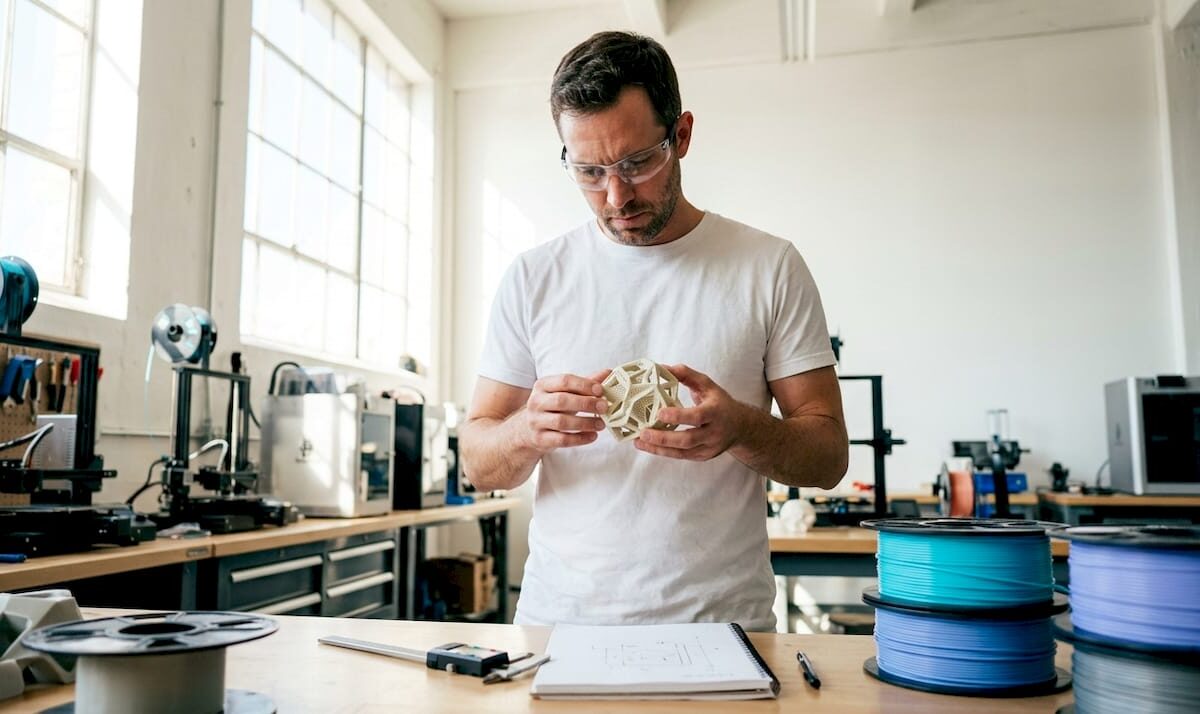
Engineer examining 3D printing model on laptop

What Is the STL File Format? A Clear Guide


TL;DR:

  • The STL file format describes 3D surface geometry as a mesh of triangles, mainly used for 3D printing. It stores only geometric data, with binary format being the most common for faster processing. Proper mesh integrity and verified scale are crucial for successful printing, as the format lacks unit or material information.

The STL file format is defined as a method for representing 3D surface geometry as a tessellated mesh of triangles, and it serves as the primary exchange format between 3D modeling software and 3D printers worldwide. STL stands for Stereolithography, a name inherited from the printing technology it was created to support. The format stores only geometric data: no color, no texture, no material properties, and no unit specification. Understanding what is STL file format means understanding its strengths and its hard limits, both of which directly affect whether your print succeeds or fails.
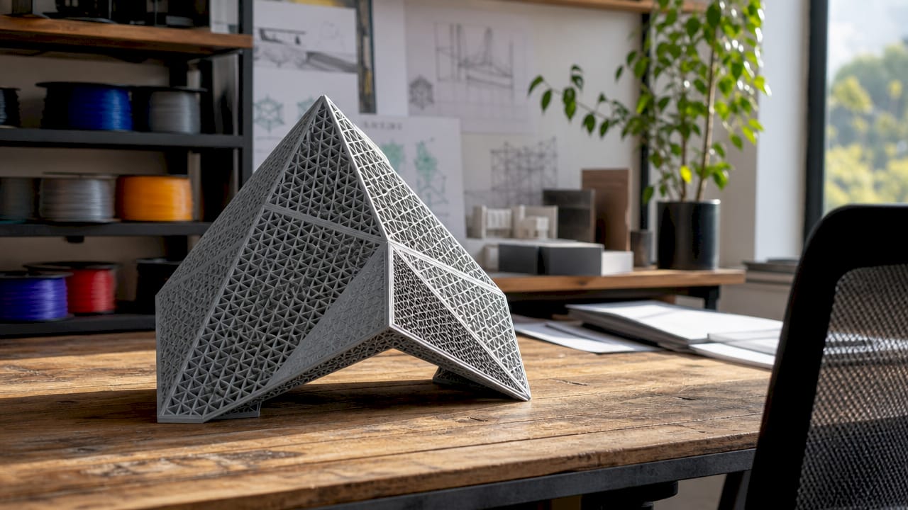
Close-up of STL triangle mesh 3D print

What is the STL file format and how does it work?

The STL format was developed by 3D Systems in 1987 to support the first commercial stereolithography 3D printers. That origin explains both its design and its limitations. The format was built for one job: describing the outer surface of a 3D object so a machine could build it layer by layer.

Every STL file encodes a 3D model as a collection of triangular facets. Each triangle is defined by three vertices and one outward-pointing normal vector. The normal vector tells the software which side of the triangle faces outward, which matters for determining the inside and outside of a solid object. Thousands or millions of these triangles combine to approximate any curved or complex surface.

What is STL file in 3D printing world?

ASCII vs. binary: two ways to store the same data

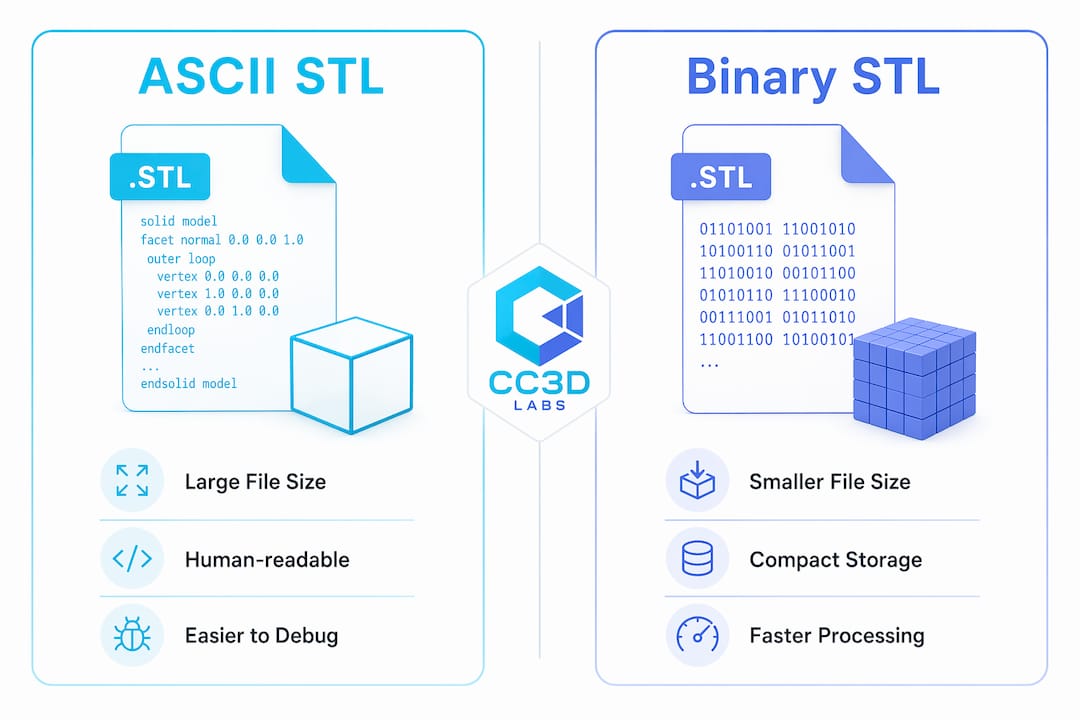
STL files come in two formats: ASCII and binary. ASCII STL writes every coordinate as human-readable text, which makes it easy to inspect but produces very large files. Binary STL stores the same data as raw numbers. Binary STL files are roughly 5 to 10 times smaller than their ASCII equivalents and load significantly faster. That size and speed advantage explains why approximately 95% of STL files in active use are binary.

The binary structure follows a fixed layout. Each file begins with an 80-byte header, followed by a 4-byte integer that records the total triangle count. After that, each triangle facet uses exactly 50 bytes: 12 bytes for the normal vector, 36 bytes for the three vertices, and 2 bytes for an attribute field that most software ignores. This deterministic layout is why binary STL loads so fast. Software can calculate exactly where each triangle starts without scanning the entire file.

Property ASCII STL Binary STL
File size Large (text-based) 5–10x smaller
Human readable Yes No
Load speed Slow Fast
Industry usage Rare ~95% of files
Header structure Text keywords 80-byte fixed header

Infographic comparing ASCII and binary STL file formats

Pro Tip: When exporting from CAD software, always choose binary STL unless you specifically need to inspect the raw file data. Binary files transfer faster, load faster in slicers, and cause fewer memory issues with high-polygon models.

How do STL files interact with 3D printers?

STL files do not control 3D printers directly. A printer cannot read an STL file and start printing. Instead, slicing software converts the geometry into machine-specific instructions called G-code, which tells the printer’s motors and extruder exactly where to move and when to deposit material. The STL file is the input; G-code is the output.

This two-step process has a major practical consequence. The STL file carries no print settings. Layer height, infill density, support structures, print speed, and material type are all decided inside the slicer, not stored in the STL. Two people can take the same STL file and produce completely different physical parts depending on their slicer settings.

The format’s compatibility is its greatest strength. Nearly every 3D printer on the market, from desktop FDM machines to industrial SLA systems, accepts STL files. Nearly every slicer program reads them without conversion. That universal support is why STL remains the default format for sharing and submitting 3D models, even as newer formats have emerged.

The 3MF format, created in 2015 by a consortium that included 3D Systems, addresses many of STL’s gaps. 3MF files can store color, material assignments, print settings, and multi-part assemblies in a single file. For multi-color or multi-material prints, 3MF is the better choice. For standard single-material prints, STL’s simplicity and universal compatibility still make it the practical default.

  • STL files store geometry only. No color, texture, material, or print settings travel with the file.
  • Slicing software reads the STL and generates G-code for the specific printer.
  • STL is compatible with virtually all consumer and professional 3D printers.
  • 3MF supports richer data but requires software that can read and write the format.
  • OBJ files carry UV maps and color data, making them better suited for visual rendering than for printing.
  • For CAD file format selection, the right choice depends on whether you need geometry only or full manufacturing data.

What are the most common STL file problems?

The single most disruptive property of STL files is that they are unitless. The format records coordinates as numbers with no attached unit. A value of “25” could mean 25 millimeters, 25 inches, or 25 centimeters. A common scaling error produces prints that are 25.4 times too large or too small because the slicer assumed millimeters while the CAD software exported in inches. Always verify the model’s dimensions inside your slicer before sending a job to print.

The second major problem is mesh integrity. A printable STL file must be “watertight,” meaning the mesh has no holes, no overlapping faces, and no inverted normals. Non-manifold geometry causes slicers to fail or produce incorrect toolpaths, which leads to print failures. A mesh with a single missing triangle can make an entire model unprintable.

Mesh errors are common because they are easy to create and hard to spot visually. A model can look perfect on screen while containing dozens of internal errors that only appear when the slicer tries to process it.

  1. Check scale first. Open the STL in your slicer and confirm the dimensions match your design intent before adjusting any other settings.
  2. Run a mesh validation. Use mesh repair tools available in most professional slicers or dedicated programs to identify holes, inverted normals, and non-manifold edges.
  3. Fix errors before slicing. Repair tools can close holes and correct normals automatically, but review the result to confirm the geometry still matches your design.
  4. Re-export cleanly from CAD. If errors are extensive, the most reliable fix is correcting the source model and re-exporting rather than patching the STL.
  5. Validate again after repair. Run a second check after any repair to confirm no new errors were introduced during the fix.

Pro Tip: Mesh validation is not optional for production parts. A model that prints successfully once can fail on the next run if the slicer interprets ambiguous geometry differently. Validate every file before every production batch. For a structured approach, the 3D design validation guide at Cc3dlabs covers this in detail.

STL vs. OBJ and 3MF: which format should you use?

STL’s simplicity is both its strength and its constraint. The format does one thing well: it describes surface geometry. That focus makes it universally readable but limits what information travels with the file. Understanding when to use STL versus alternative formats saves time and prevents avoidable errors.

OBJ is the most common alternative for visual work. OBJ files support UV texture maps, vertex colors, and material libraries, which makes them the standard for game assets, film rendering, and visual design. For 3D printing, OBJ’s extra data is largely irrelevant unless the printer supports full-color output. Most FDM printers ignore color data entirely.

3MF is the format most likely to replace STL for manufacturing workflows over the next decade. It stores geometry, color, materials, print settings, and multi-part assemblies in a single compressed file. 3MF was created in 2015 specifically to address the gaps that STL left open. The format is gaining adoption in professional environments, particularly for multi-material and multi-color printing.

Format Color/Texture Print settings Multi-part Best use case
STL No No No Single-material printing, universal sharing
OBJ Yes No No Visual rendering, color models
3MF Yes Yes Yes Multi-material, full manufacturing data

STL remains the backbone of single-material 3D printing because its simplicity guarantees compatibility. No slicer or printer rejects an STL file. That guarantee matters in production environments where reliability outweighs features. For printable templates and ready-to-print geometry, resources like CacheWerk’s 3D print files demonstrate how STL’s universal format makes sharing models across platforms frictionless.

Key Takeaways

The STL file format remains the most universally supported method for sharing 3D geometry for printing, but its lack of units, color, and material data makes mesh quality and slicer settings the true determinants of print success.

Point Details
STL stores geometry only No color, texture, material, or unit data travels with the file.
Binary format dominates ~95% of STL files are binary, which is 5–10x smaller than ASCII.
Slicers bridge the gap Slicing software converts STL geometry into printer-specific G-code.
Unitless files cause errors Always verify model dimensions in your slicer to avoid 25.4x scaling mistakes.
Mesh integrity is critical A watertight, manifold mesh is required for a successful print.

Why STL’s simplicity is still its superpower

After working with 3D files across dozens of production runs, I’ve come to a conclusion that surprises most people new to the field: the format matters far less than the mesh. I’ve seen beautifully structured 3MF files fail on the print bed because the underlying geometry had inverted normals. I’ve also seen bare-bones STL files produce flawless functional parts because the mesh was clean and the scale was verified.

The instinct to blame the format when a print fails is understandable but usually wrong. Print failures trace back to poor mesh health, not to STL’s age or feature set. The format is a container. What you put inside it determines the outcome.

That said, I do think the industry is at a genuine inflection point. 3MF adoption is accelerating in professional shops, and for good reason. Embedding print settings directly in the file eliminates a whole category of human error. When a client sends a 3MF with verified settings, the margin for misinterpretation shrinks considerably.

My recommendation for professionals: master STL handling first. Understand the binary structure, validate every mesh, and build a habit of checking scale before every job. Once those fundamentals are solid, adding 3MF to your workflow is straightforward. Skipping the fundamentals and jumping to richer formats just moves the problem around. The step-by-step 3D printing guide at Cc3dlabs is a good reference for building that foundation systematically.

STL will not disappear. Its universality is too valuable for everyday single-material work. But the professionals who thrive will be the ones who treat it as a precision instrument, not a default checkbox.

— Justin

Cc3dlabs handles your STL files from upload to finished part

Working with STL files at a professional level requires more than a clean mesh. It requires experience with how geometry behaves across different materials, layer heights, and printer configurations.

https://cc3dlabs.com

Cc3dlabs, based near Philadelphia, reviews every submitted STL file for mesh integrity, scale accuracy, and printability before a single layer is deposited. The team handles custom 3D printing services for prototypes, functional parts, and batch production, serving clients locally and internationally. Whether you need a single prototype or a production run, Cc3dlabs brings the technical depth to get your geometry off the screen and into your hands accurately. Request a free online estimate directly from the website.

FAQ

What does STL stand for in 3D printing?

STL stands for Stereolithography, the 3D printing technology developed by 3D Systems in 1987 for which the format was originally created. The name has since become synonymous with the file format itself across all 3D printing technologies.

What data does an STL file contain?

An STL file contains only surface geometry encoded as a mesh of triangular facets, each defined by three vertices and a normal vector. It stores no color, texture, material properties, unit specification, or print settings.

How do I open an STL file?

STL files open in any 3D slicer program, most CAD applications, and dedicated mesh viewers. Common options include slicer programs used for FDM and SLA printing, as well as browser-based viewers that require no software installation.

What is the difference between STL and OBJ files?

STL files store only surface geometry and are optimized for 3D printing workflows. OBJ files add UV texture maps, vertex colors, and material libraries, making them better suited for visual rendering than for manufacturing.

Why do STL files cause scaling errors?

STL files have no unit specification, so the same coordinate value can be interpreted as millimeters or inches depending on the software. A mismatch between the exporting CAD tool and the importing slicer produces prints that are 25.4 times too large or too small.
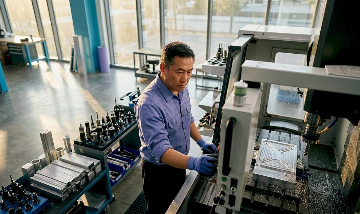
Technician operating CNC milling machine in workshop

What Is Digital Fabrication? A Complete Guide


TL;DR:

  • Digital fabrication involves computer-controlled machines transforming digital designs into physical objects with minimal human intervention. It encompasses various methods like 3D printing, CNC milling, and laser cutting, based on a CAD to CAM workflow. Its main benefits are precision, speed, and customization, but it requires skill and investment for effective use.

Digital fabrication is defined as the process of using computer-controlled machines to transform digital design files into physical objects, with minimal human intervention at the production stage. The field originated in the 1950s and has since become a core skill in architecture, engineering, product development, and artistic design. Understanding what is digital fabrication means recognizing that it covers far more than 3D printing. It spans CNC milling, laser cutting, water jet cutting, and forming processes, all driven by the same fundamental workflow: a digital file controls the machine, and the machine builds the part.

What is digital fabrication and how does it work?

Digital fabrication technology operates through a two-stage workflow: CAD to CAM. CAD, or computer-aided design, is where you create the digital model. CAM, or computer-aided manufacturing, translates that model into machine-readable instructions called G-code or toolpaths. The machine then executes those instructions with a level of repeatability no human hand can match.

"Beyond 3D printers": Understanding Digital Fabrication Practices for the Education of Visually ...

The CAD to CAM workflow is the foundation of every digital fabrication process. Once a design is finalized in software like Autodesk Fusion 360 or SolidWorks, the CAM software calculates the exact movements the machine must make. That file goes directly to the machine, which executes the build automatically.

The main machine types in a digital fabrication ecosystem include:

  • 3D printers (FDM, SLA, SLS): build objects layer by layer from plastic, resin, or powder
  • CNC mills: remove material from a solid block using rotating cutting tools
  • Laser cutters: use a focused beam to cut or engrave sheet materials like wood, acrylic, or metal
  • Vinyl cutters: trace vector paths to cut adhesive films or thin sheets
  • Water jet cutters: use high-pressure water mixed with abrasive to cut thick metals and composites

The key distinction between digital and analog fabrication is control. In analog fabrication, a human guides the tool, even when using jigs or templates. In digital fabrication, precise digital instructions control every movement. That shift eliminates a major source of human error and makes production far more consistent.

Pro Tip: Before sending any file to a machine, run a simulation in your CAM software. Catching a toolpath collision on screen costs nothing. Catching it on the machine costs material, time, and sometimes the tool itself.

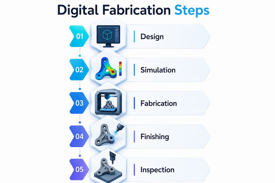
Infographic outlining digital fabrication process steps

What are the main types of digital fabrication methods?

Digital fabrication processes fall into three categories: additive, subtractive, and formative manufacturing. Each category uses distinct machines, suits different materials, and produces different results. Choosing the wrong category for a project wastes time and money.

Engineer overseeing 3D printer producing prototype

Additive manufacturing builds objects by depositing material layer by layer. 3D printing is the most common example. It excels at complex internal geometries, lightweight structures, and low-volume custom parts. Material waste is minimal because you only deposit what the part requires.

Subtractive manufacturing starts with a solid block and removes material until the part remains. CNC milling and laser cutting are the primary tools. Subtractive methods produce parts with tighter tolerances and better surface finishes than most additive processes. They work well with metals, hardwoods, and engineering-grade plastics.

Formative manufacturing uses digital control to shape, bend, fold, or mold material without adding or removing it. Processes like CNC bending, thermoforming, and press braking fall here. Formative methods are fast for high-volume production and work well with sheet metal and thermoplastics.

Method Key advantage Main limitation Typical materials Best for
Additive Complex geometry, low waste Slower, lower strength Plastics, resins, metals Prototypes, custom parts
Subtractive Tight tolerances, strong parts More material waste Metals, wood, plastics Functional components
Formative Fast at volume, consistent High tooling cost Sheet metal, thermoplastics Production runs

Pro Tip: For most prototyping projects, start with additive manufacturing to validate geometry, then switch to subtractive or formative methods for the production version. This sequence saves significant tooling cost.

What are the main applications of digital fabrication?

Digital fabrication technology serves four major application areas, each with distinct requirements and benefits.

  1. Rapid prototyping. Designers and engineers use digital fabrication to validate concepts quickly without committing to expensive tooling. A part that once took weeks to produce by hand can now be printed overnight and tested the next morning. The ability to iterate fast is the single biggest competitive advantage digital fabrication gives product developers.

  2. Precision manufacturing. CNC milling and laser cutting produce parts to tolerances measured in thousandths of an inch. Aerospace brackets, medical device housings, and automotive jigs all rely on subtractive digital fabrication for this level of accuracy. The automated precision of these processes reduces human error and minimizes material waste compared to traditional manual methods.

  3. Architectural and artistic design. Architects use digital fabrication to produce building components with complex geometries that would be impossible to create by hand. Parametric facades, custom joinery, and scale models all come out of the same CAD to CAM pipeline. Artists use laser cutters and CNC routers to create intricate sculptures and installations that require machine-level precision.

  4. Education and makerspaces. Schools and community fabrication labs use digital fabrication tools to teach design thinking, engineering, and problem-solving. Students move from a sketch to a physical object in a single session. That near-instant feedback loop accelerates learning in a way that traditional shop class never could.

The integration of design and fabrication into a nearly simultaneous process is what makes digital fabrication so powerful across all four areas. You design it, you make it, you test it, and you improve it. That cycle used to take months. Now it takes days or hours.

Cc3dlabs applies this same workflow to custom 3D printing for engineers and product developers near Philadelphia, producing functional prototypes and batch parts with fast turnaround times.

What are the benefits and challenges of digital fabrication?

The benefits of digital fabrication are concrete and measurable. The challenges are real but manageable with the right preparation.

Core benefits:

  • Precision: Machines execute digital instructions exactly, producing consistent results across every unit in a batch
  • Waste reduction: Additive processes use only the material the part requires; subtractive processes recycle chips and offcuts
  • Speed: The iterative feedback loop between design and fabrication compresses development timelines
  • Customization: Every part can be unique without retooling, because the design file is the only thing that changes
  • Reduced human error: Digital control eliminates the variability introduced by manual tool guidance

Common challenges:

  • Upfront cost: Professional CNC machines and industrial 3D printers carry significant purchase and maintenance costs
  • Skill requirements: Operating CAD and CAM software requires training. A poorly prepared file produces a poorly made part
  • Material constraints: Not every material works with every process. Matching material to method requires experience
  • Software learning curve: CAD platforms like Fusion 360 and SolidWorks take months to learn at a production level

The comprehensive digital fabrication ecosystem including CNC milling, laser cutting, and forming processes requires unified CAD/CAM workflows to function efficiently. Teams that invest in workflow standardization recover their setup costs faster than those who treat each machine as a separate silo.

Pro Tip: Build a material and process matrix before starting any new project. List your geometry requirements, tolerance needs, and volume, then match them to the right fabrication method. Skipping this step is the most common reason projects go over budget.

Key Takeaways

Digital fabrication is the most direct path from a digital design to a physical object, and choosing the right process category determines whether a project succeeds or fails.

Point Details
CAD to CAM is the core workflow Every digital fabrication process starts with a design file and ends with machine-readable instructions.
Three categories cover all methods Additive, subtractive, and formative manufacturing each suit different materials, tolerances, and volumes.
Precision and speed are the top benefits Digital control eliminates human error and compresses design-to-part timelines significantly.
Prototyping drives the most value Rapid iteration using digital fabrication cuts development time and reduces tooling costs before production.
Skill and cost are the main barriers CAD/CAM proficiency and equipment investment are the two factors that determine adoption speed.

Why the “3D printing equals digital fabrication” myth costs engineers time

The most persistent misconception I see among engineers new to this field is treating digital fabrication and 3D printing as synonyms. They are not. 3D printing is one tool in a much larger toolkit, and defaulting to it for every project leads to parts that are weaker, slower to produce, or more expensive than they need to be.

I have watched product teams spend weeks iterating on FDM-printed structural brackets, only to discover that a CNC-milled aluminum version would have passed load testing on the first attempt. The additive process was the wrong choice for that geometry and that material. The team knew how to use a 3D printer. They did not know when not to use one.

The real skill in digital fabrication is process selection. That means understanding the additive manufacturing category deeply enough to know its limits, and knowing when subtractive or formative methods will produce a better outcome. It also means building an iterative feedback loop into every project. Practitioners who use simulations and physical mock-ups to test assumptions before committing to final production consistently produce better parts at lower cost.

The future of this field belongs to engineers and creators who treat digital fabrication as a system, not a single machine. The tools will keep improving. The workflow discipline is what separates good outcomes from great ones.

— Justin

Cc3dlabs: professional digital fabrication for your next project

Cc3dlabs brings professional-grade digital fabrication to engineers, product developers, and creators near Philadelphia and beyond. The team specializes in custom filament-based 3D printing, multi-color printing, CAD modeling, and professional handheld 3D scanning (accuracy to ~0.1 mm), all built around the same CAD to CAM workflow this article covers.

https://cc3dlabs.com

Whether you need a single functional prototype or a batch of precision parts, Cc3dlabs delivers accurate results with fast turnaround times. The process starts with your design file or a free consultation if you need modeling support. Explore the full range of 3D printing services to find the right solution for your project, or check out what is possible with 3D printing for product innovation before you commit to a fabrication method.

FAQ

What is digital fabrication in simple terms?

Digital fabrication is the process of using computer-controlled machines to build physical objects directly from digital design files. The machine reads the file and executes the build automatically, with minimal human intervention.

How does digital fabrication differ from traditional manufacturing?

Traditional manufacturing relies on manual tool guidance, even when jigs are used. Digital fabrication uses precise digital instructions to control every machine movement, which eliminates human variability and produces consistent results across every part.

What are the three main types of digital fabrication?

The three categories are additive manufacturing, which builds objects layer by layer; subtractive manufacturing, which removes material from a solid block; and formative manufacturing, which uses digital control to shape or mold material without adding or removing it.

Is 3D printing the same as digital fabrication?

No. Digital fabrication is a broad field that includes 3D printing, CNC milling, laser cutting, water jet cutting, and forming processes. 3D printing is one method within that larger category.

What industries use digital fabrication most?

Architecture, aerospace, automotive, medical device manufacturing, product design, and education all rely heavily on digital fabrication for prototyping, precision parts, and complex geometry production.

Female engineer reviewing 3D CAD model on monitor

Why 3D Model Verification Is Important for Engineers


TL;DR:

  • D model verification ensures geometric accuracy, structural integrity, and production readiness before manufacturing begins. It prevents costly downstream errors by detecting hidden issues early through systematic checks and structured milestones.

3D model verification is the proactive process of checking digital models for geometric accuracy, structural integrity, and production readiness before a single part is manufactured. Skip it, and you risk cascading errors: wrong units, broken mesh geometry, and incompatible file formats that surface only after fabrication has started. For product developers and engineers, understanding why 3D model verification is important is not a theoretical exercise. It is the difference between a clean production run and an expensive rework cycle that kills your schedule.

Why 3D model verification is important: the core case

A visually correct CAD model can still contain hidden errors like broken references or faulty geometry that cause manufacturing and documentation failures. That is the central problem with relying on visual inspection alone. What looks right on screen can be fundamentally wrong in the data.

The industry term for this process is CAD validation or 3D model quality assurance, and it covers far more than a visual check. It includes mesh integrity tests, unit consistency checks, topology evaluation, and downstream compatibility verification. Engineers who treat these as optional steps tend to discover their errors at the worst possible time: after tooling has been cut or parts have been printed.

Spatial and geometric tests are risk management steps that prevent downstream pipeline failures. Failing to run them early means discarding hours of subsequent texturing, rigging, or manufacturing prep work. The cost is not just time. It is the compounding effect of every downstream step built on a flawed foundation.

Structured, multi-stage review milestones such as 30%, 60%, and 90% audits are professional standards in 2026 to catch errors early and prevent cascading issues. These checkpoints are not bureaucratic overhead. They are the mechanism that keeps small geometry problems from becoming full production failures.

What are the key components of effective 3D model verification?

Effective verification checks several distinct layers of a model, and each layer catches a different class of error.

Infographic depicting steps of 3D model verification process

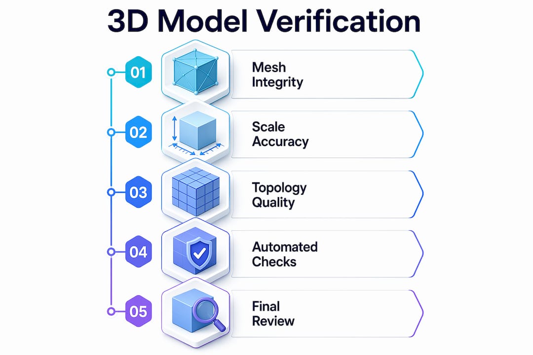
Mesh integrity is the first line of defense. Common faults include reversed normals, non-manifold edges, and open shells. A non-manifold edge, for example, is one shared by more than two faces. Slicers and manufacturing software cannot process these correctly, which means a model that looks solid will fail at the fabrication stage.

Scale accuracy and unit consistency are equally critical. A model built in millimeters but exported as inches will produce a part that is 25.4 times the intended size. This error is trivially easy to make and surprisingly common when files move between different CAD environments or teams.

Topology quality determines how a model behaves in downstream workflows. Good topology supports deformation, subdivision, and efficient rendering essential for production use. For functional parts, poor topology can cause stress concentration points that only appear under load testing.

Verification criterion Common fault Impact on production
Mesh integrity Non-manifold edges, open shells Slicer failure, fabrication rejection
Scale and units Unit mismatch between environments Incorrect part dimensions
Topology quality Irregular polygon flow, T-junctions Deformation errors, rendering artifacts
UV and texture mapping UV overlap, incorrect color space Visual defects in rendered or printed parts
Watertightness Holes in mesh surface Failed 3D print, unusable geometry

The table above shows why no single check is sufficient. Each criterion targets a different failure mode.

Pro Tip: Run a slicer pass as a final mesh integrity check before submitting any model for fabrication. A clean slicer pass rate is one of the strongest predictors of a successful print.

Automated quality assurance catches 95% of common mesh and texture flaws, freeing engineers to focus manual effort on nuanced topology and functional assessments. That 5% gap is where expert human review earns its value.

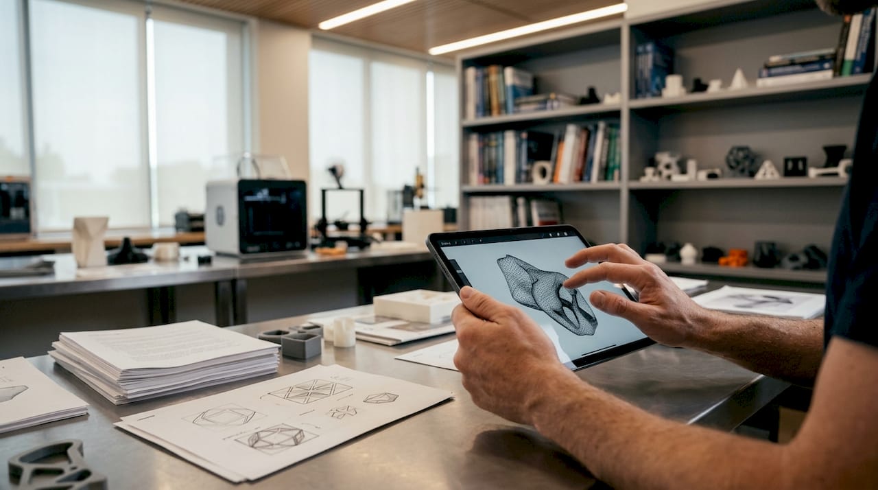
Hands using tablet for 3D model verification

How does 3D model verification prevent costly downstream errors?

The timing of error discovery is everything in product development. An error caught at the 30% design milestone costs a fraction of what the same error costs after manufacturing has begun. This is not an opinion. It is a structural feature of how production pipelines work: every downstream step adds cost and time to any upstream mistake.

CAD validation reduces rework and supports compliance by confirming models meet dimensional and functional requirements before production. Validated models also improve coordination between design, manufacturing, suppliers, and stakeholders. That coordination benefit alone justifies the time investment.

The most common costly errors that verification prevents include:

  1. Incorrect units or scale causing parts to be fabricated at the wrong size, requiring full reprints or remachining.
  2. Non-manifold geometry causing slicer failures that halt production until the model is repaired.
  3. Missing or broken references in assembly files that cause incorrect bill-of-materials outputs and procurement errors.
  4. Incompatible geometry between mating parts that only surfaces during physical assembly, requiring redesign.
  5. Wrong color spaces or UV errors in models destined for multi-color or textured printing, causing visual defects in finished parts.

Each of these errors is detectable before fabrication with a structured verification workflow. Each becomes significantly more expensive after fabrication has started.

A CAD model’s readiness is defined by downstream compatibility. If later pipeline steps require manual repair, the model fails validation regardless of how good it looks. Avoiding the “polish later” mindset is the single most effective habit engineers can build.

Pro Tip: Treat the 30% review milestone as your geometry checkpoint. Confirm mesh integrity, units, and scale before investing time in detailed features or surface finishing.

For engineers using part validation in 3D printing, catching errors at the design stage eliminates the most common causes of print failure and part rejection.

What tools and workflows make verification more effective?

Automated verification tools handle the high-volume, rule-based checks that would take hours to run manually. Automated scripts efficiently filter fundamentally broken models, saving manual inspection time for advanced subjective assessment like topology flow. This hybrid approach is the current best practice for production-ready asset pipelines.

A tool-agnostic mindset centered on core 3D spatial principles is more valuable than relying on any single software validator. Models must survive across multiple pipelines, and a check that passes in one environment may fail in another if the underlying geometry is marginal.

Recommended verification techniques for engineers:

  • Automated mesh analysis: Checks for non-manifold edges, reversed normals, open shells, and degenerate faces. Most slicer software includes basic versions of these checks.
  • Bounding box validation: Confirms the model occupies the correct volume and that scale has not been corrupted during export.
  • UV and color space checks: Verifies UV utilization thresholds and correct color spaces (sRGB for display, Linear for rendering) to prevent texture errors.
  • Watertightness testing: Confirms the mesh is a closed solid with no holes, which is a hard requirement for most 3D printing workflows.
  • Topology review: Manual or semi-automated assessment of polygon flow, edge loops, and face count relative to the model’s intended use.

Validation is the indispensable gatekeeper that converts generative AI models into reliable, shippable assets by enforcing deterministic outputs and quality criteria. As generative modeling tools become more common in product development, this gatekeeper role becomes more critical, not less.

Pro Tip: Never defer spatial validation to the end of your workflow. Run geometry and scale checks immediately after the initial model is built, before any texturing or assembly work begins.

For a structured approach to validating 3D designs within manufacturing workflows, building these checks into your standard operating procedure is the fastest way to reduce defect rates.

How should product developers integrate verification into their process?

Verification works best when it is built into the project timeline from the start, not added as a final gate before production. The 3D modeling process for businesses should include defined verification checkpoints at each major milestone.

Project phase Verification activities Goal
Concept (30%) Geometry check, unit confirmation, scale validation Confirm foundational model integrity
Development (60%) Topology review, assembly fit check, reference validation Catch functional and compatibility errors
Pre-production (90%) Full mesh audit, slicer pass, UV and texture check Confirm production readiness
Final release File format validation, documentation check Ensure handoff package is complete

Cross-functional coordination between design, manufacturing, and quality teams is what makes this schedule work. Each team brings a different perspective on what “correct” means for a model. Design teams check intent. Manufacturing teams check producibility. Quality teams check compliance. All three views are needed.

Defining verification criteria early, before modeling begins, prevents the most common source of late-stage conflict: disagreement about what the model was supposed to achieve. A shared checklist, agreed upon at project kickoff, gives every team a common standard to work toward.

Drafting standards in 3D modeling provide the structured review checkpoints that keep multi-team projects aligned and reduce handoff errors between design and production.

Pro Tip: Embed verification criteria into your project brief at kickoff. When every team knows the acceptance standards from day one, late-stage surprises drop dramatically.

Verification is not a formality. It is the work.

I have reviewed hundreds of models that looked production-ready on screen and failed within the first automated check. The pattern is consistent: teams that treat verification as a final approval step always find their worst errors at the worst time. Teams that build it into every milestone find the same errors when they are still cheap to fix.

The most underestimated risk in product development is not a bad design. It is a good design with a bad model. A brilliant concept built on non-manifold geometry or mismatched units will fail in fabrication just as reliably as a poor design. The geometry does not care how good the idea is.

Generative AI tools are making this problem more acute, not less. AI-generated models can look convincing while containing structural errors that no human would introduce manually. Machine-verifiable tests for topology, watertightness, and schema conformance are now essential for any team using generative modeling in their pipeline. The speed of AI generation means errors can propagate faster than ever before.

My strongest recommendation is this: build a verification culture, not just a verification step. When every engineer on your team treats geometry integrity as their personal responsibility, not the QA team’s problem, error rates drop and project timelines stabilize. Verification is not overhead. It is the work.

— Justin

Cc3dlabs supports precision from model to finished part

Cc3dlabs works with product developers and engineers near Philadelphia and ships nationally, providing professional 3D printing services built around verified, high-accuracy models. Every project starts with a model review to confirm the file is production-ready before printing begins.

https://cc3dlabs.com

Validated CAD files and high-accuracy 3D scan data feed directly into Cc3dlabs’ filament-based printing workflow, producing prototypes and functional parts that match design intent. Whether you need a single prototype or a batch production run, Cc3dlabs offers free online estimates, design support, and fast turnaround. Submit your model for a free estimate and get a clear picture of what your verified design will cost to produce.

FAQ

What is 3D model verification?

3D model verification is the process of checking a digital model for geometric accuracy, unit consistency, mesh integrity, and downstream compatibility before fabrication. It is also called CAD validation or 3D model quality assurance.

Why do visually correct models still fail in production?

A model can appear correct on screen while containing hidden errors like non-manifold edges, broken references, or wrong units. These errors only surface when the model enters a slicer, manufacturing software, or assembly workflow.

When should verification happen in a project?

Verification should happen at the 30%, 60%, and 90% milestones of a project, not only at the end. Early checks catch foundational errors before downstream work amplifies their cost.

How does automated verification differ from manual review?

Automated verification catches up to 95% of common mesh and texture flaws through rule-based checks. Manual review handles nuanced assessments like topology flow and functional fit that require expert judgment.

What is the biggest risk of skipping 3D model verification?

The biggest risk is discovering errors after fabrication has started, when the cost to correct them is highest. Unverified models frequently cause slicer failures, incorrect part dimensions, and assembly incompatibilities that require full redesign.


Key takeaways

3D model verification is the most cost-effective risk management step in product development, and errors caught before fabrication cost a fraction of what they cost after production begins.

Point Details
Verify early and often Run geometry and scale checks at the 30%, 60%, and 90% project milestones.
Automate first, then review Automated tools catch 95% of common flaws; use manual review for topology and functional fit.
Visual inspection is not enough Hidden errors like non-manifold edges and wrong units require systematic checks to detect.
Define criteria at kickoff Agree on acceptance standards before modeling begins to prevent late-stage team conflicts.
Verification enables AI workflows Machine-verifiable tests are now required to make generative AI models production-ready.
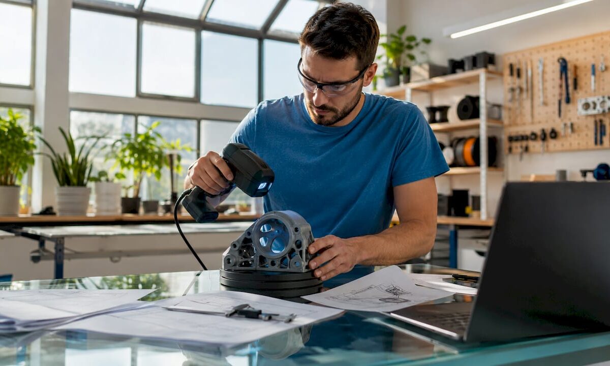
Engineer scanning mechanical part with 3D scanner

What Is Scan to CAD? A 2026 Workflow Guide


TL;DR:

  • Scan to CAD transforms raw 3D scan data into editable, parametric models for manufacturing and design purposes. The process involves scanning, data export, alignment, feature extraction, and exporting the final CAD file, with reconstruction being the most time-consuming step. Advanced tools and AI-assisted software help streamline the workflow, but operator skill remains essential for accuracy and usability.

Scan to CAD is the process of converting raw 3D scan data into editable, parametric CAD files used for design, manufacturing, and prototyping. Formally called reverse engineering from scan data, this workflow transforms millions of captured spatial points into structured models in formats like STEP, SLDPRT, or OBJ. Tools like Geomagic, Autodesk Fusion 360, and Creaform Metrology Suite sit at the center of this process. Whether you are recreating a broken part, building a custom fixture, or digitizing a physical object for redesign, scan to CAD gives you a precise, modifiable starting point that raw scan files simply cannot provide.

What is the scan-to-CAD workflow, step by step?

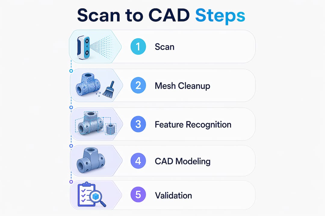
The scan-to-CAD process follows a five-step lifecycle: scanning, data export and import, alignment, feature extraction, and exporting parametric files. Each stage builds on the last, and skipping any one of them produces unreliable results downstream.

  1. Capture the object with a 3D scanner. Structured light scanners, laser scanners, and photogrammetry rigs all capture surface geometry as a point cloud. The output is a dense collection of XYZ coordinates that represents the physical object’s shape.

  2. Export the scan in a compatible file format. OBJ files carry color and texture, STL files carry geometry only, and STEP files carry parametric engineering data. Choosing the right format at this stage saves significant rework later. STL works for geometry checks; STEP is the target for fully editable engineering models.

  3. Import and align the mesh in CAD software. Once inside a tool like Autodesk Fusion 360 or Autodesk ReCap, the mesh must be oriented correctly. Misalignment in this step causes design errors that compound through every subsequent modeling decision.

  4. Extract features and reconstruct geometry. This is the most demanding step. You identify planes, cylinders, fillets, and other geometric primitives in the mesh, then model them as parametric features. Auto-surfacing the raw mesh almost always creates unmanageable files. Fitting primitives to the mesh produces clean, editable CAD geometry.

  5. Export the finished parametric model. The final output is a native CAD file, typically STEP or a format like SolidWorks SLDPRT, ready for modification, simulation, or direct manufacturing.

Pro Tip: A basic scan-to-CAD project can be completed in roughly 24 hours with the right hardware and software combination. Plan your scanning session carefully so you spend that time on modeling, not on fixing scan data.

Which tools are used for scan to CAD in 2026?

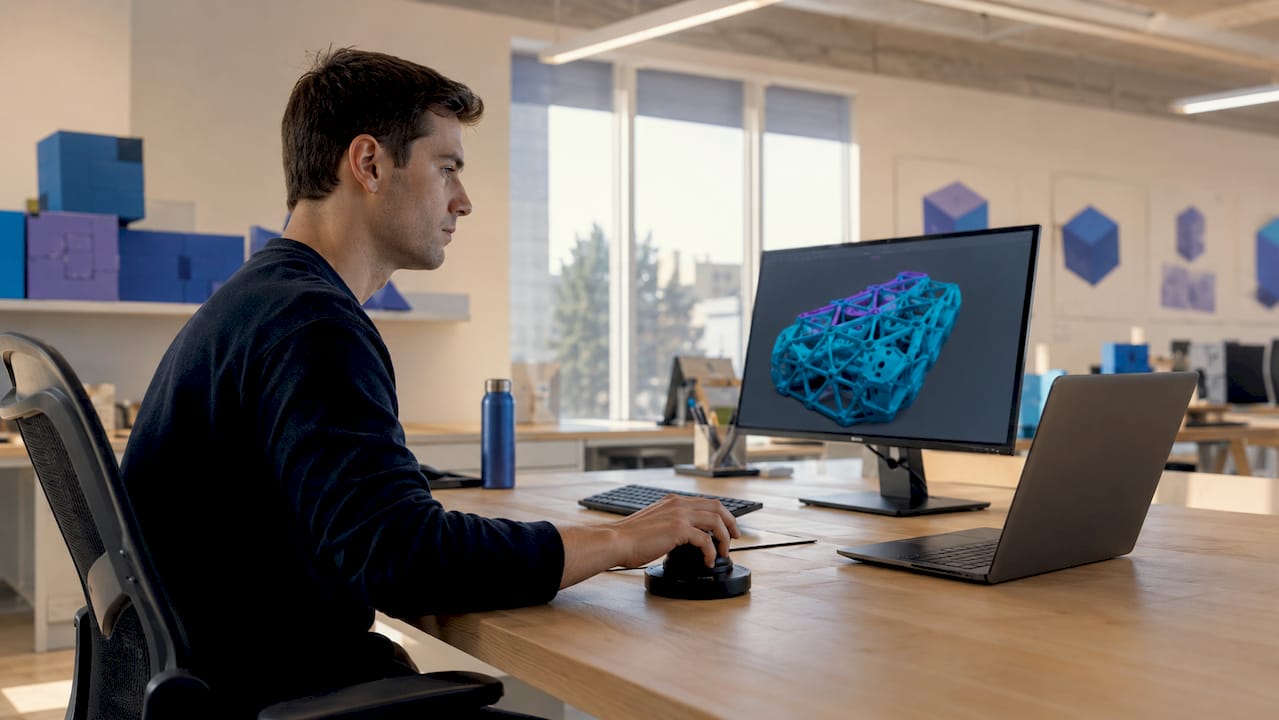
Designer editing 3D mesh in CAD software

The scan-to-CAD software and hardware market has matured significantly. The right combination depends on your accuracy requirements, budget, and the complexity of the part you are working with.

Professional-grade scanners:

  • Creaform HandySCAN and the Creaform Metrology Suite handle high-accuracy industrial scanning and include a dedicated Scan-to-CAD module that automates several post-processing steps.
  • Artec 3D scanners, including the Artec Eva and Artec Leo, are widely used for medium-complexity parts and organic shapes.

Mobile and accessible options:

  • iPhones and iPads equipped with LiDAR sensors (iPhone 12 Pro and later) provide a low-cost entry point for less demanding projects. Apps like Polycam export directly to formats compatible with Fusion 360.
  • AI-assisted tools reduce turnaround times by automating manual stages like point-cloud tracing, making mobile LiDAR a practical option for concept work and reference modeling.

CAD and post-processing software:

The trend in 2026 is toward AI-assisted mesh cleanup and feature recognition. These tools do not replace engineering judgment, but they cut the time spent on repetitive cleanup tasks by a meaningful margin. For complex organic shapes, Geomagic still leads. For prismatic mechanical parts, Fusion 360 with a clean STL import is often the fastest path.

What challenges do users face when converting scan data to CAD?

The biggest misconception in scan to CAD is treating the scan data as a finished model. A 3D scan is a visual reference blueprint. It shows you what the object looks like, not how it was designed. Getting an editable CAD model requires reconstruction, not conversion.

“A 3D scan is only a visual reference blueprint; manual reconstruction is needed to get an editable CAD model.” — Einstar Reverse Engineering Guide

Auto-surfacing raw scan meshes often leads to unmanageable files with thousands of irregular faces. The correct approach is to use the mesh as a dimensional reference and fit parametric features, like cylinders, planes, and fillets, on top of it. This takes more time but produces a model you can actually modify.

Mesh cleanup and alignment are the other major friction points. Dirty meshes with holes, noise, or overlapping faces cause feature extraction to fail or produce inaccurate geometry. Tools like Autodesk ReCap help orient and clean scans before they enter the CAD environment, but mesh cleanup and point cloud alignment still require operator attention and judgment.

Infographic detailing scan to CAD workflow steps

The post-scan processing phase consistently takes more time than the scanning itself. Experienced practitioners budget two to four times as much time for reconstruction as for data capture. If you are new to the CAD modeling workflow, that ratio is often surprising and worth planning for from the start.

Pro Tip: Not every scan needs to become a fully parametric solid model. For fit-check or reference work, using the scan mesh as an overlay inside Fusion 360 is faster and often sufficient. Match your modeling effort to the actual project goal.

How is scan to CAD applied in real prototyping and design workflows?

Scan to CAD has three primary applications in practical design and manufacturing work: reverse engineering broken or legacy parts, creating custom fixtures and enclosures, and accelerating product iteration.

Reverse engineering broken or legacy parts

When a part breaks and no drawing exists, a 3D scan gives you the geometry you need to recreate it. Editable scan-to-CAD files enable modifications like thickening ribs, adjusting tolerances, or changing materials before the part goes back into production. This is far faster than measuring by hand and rebuilding from scratch.

Custom fixture and enclosure design

Designers scan an existing assembly or environment, then model a new part directly around the scan data. A custom bracket, housing, or adapter can be designed to fit perfectly because the scan captures the actual geometry of the mating surfaces, not a nominal drawing that may not reflect real-world tolerances.

Accelerating product iteration with 3D printing

The combination of scan to CAD and 3D printing creates a tight iteration loop. You scan a physical prototype, modify the CAD model, print a revised version, and test it. Each cycle takes hours instead of days. This workflow is especially effective for ergonomic parts, consumer products, and any design where fit and feel matter as much as function.

Application Primary benefit Typical output format
Reverse engineering legacy parts Recreate geometry without original drawings STEP, SLDPRT
Custom fixture design Fit new parts to existing assemblies STEP, STL for printing
Product iteration with 3D printing Rapid physical testing of design changes STL for FDM or SLA printing
Digital asset creation Preserve physical objects as editable models OBJ, STEP

The 3D modeling process for businesses follows a similar logic: scan data provides the dimensional foundation, and CAD modeling adds the engineering intent. The two together produce results that neither can achieve alone.

Key takeaways

Scan to CAD converts physical objects into editable parametric models by combining accurate scan data with deliberate CAD reconstruction, and the quality of the output depends entirely on the operator’s modeling skill and process discipline.

Point Details
Scan data is a blueprint, not a model Raw scans require manual reconstruction to become editable CAD geometry.
Five-step workflow Scanning, export, alignment, feature extraction, and parametric export define every successful project.
Tool selection matters Geomagic Design X leads for organic shapes; Fusion 360 works well for prismatic mechanical parts.
Post-processing takes the most time Budget two to four times more time for reconstruction than for the scan itself.
Match effort to project goals Reference overlays in Fusion 360 can replace full solid modeling when fit-check is the only requirement.

Why scan to CAD is harder than it looks, and worth it anyway

I have seen a lot of people come into scan-to-CAD projects expecting the software to do the heavy lifting. They scan an object, import the mesh, hit a button, and expect a clean parametric model to appear. That is not how it works, and that gap between expectation and reality is where most projects stall.

The value of scan data is tied entirely to the operator’s ability to interpret and reconstruct design intent accurately. A mesh tells you where the surface is. It does not tell you whether that surface is supposed to be a 25mm cylinder or a 24.97mm cylinder with manufacturing variation. That judgment call is yours, and it requires both CAD skill and domain knowledge about the part you are modeling.

What I find genuinely exciting about the current state of the tools is that AI-assisted feature recognition in software like Geomagic Design X is starting to close that gap. It does not eliminate the need for engineering judgment, but it handles the tedious parts of mesh cleanup and primitive fitting faster than any manual workflow. For someone learning the process, that means you can focus your attention on the decisions that actually matter.

My honest recommendation: start with a simple prismatic part, something with flat faces, clear holes, and obvious geometry. Get that workflow clean before you attempt organic shapes or complex assemblies. The skills transfer directly, and you will build confidence in the process before the difficulty ramps up.

— Justin

Take your scan-to-CAD projects further with Cc3dlabs

If you are working on a project that requires precise scan data or professional CAD modeling support, Cc3dlabs offers professional handheld 3D scanning (accuracy to ~0.1 mm) and full CAD modeling services from its facility near Philadelphia. Whether you need a single part scanned and reconstructed or a full reverse engineering workflow for a production component, the team brings the equipment and expertise to deliver accurate, print-ready files.

https://cc3dlabs.com

From scan capture through to on-demand 3D printing of the finished model, Cc3dlabs handles the complete workflow. Local pickup is available, and shipping options cover clients across the United States and internationally. Request a free online estimate directly from the website to get started.

FAQ

What is scan to CAD in simple terms?

Scan to CAD is the process of taking a 3D scan of a physical object and converting that scan data into an editable CAD model. The result is a parametric file you can modify, manufacture, or 3D print.

What file formats are used in the scan-to-CAD process?

OBJ is preferred for color and texture, STL for geometry-only 3D printing, and STEP for parametric engineering models. STEP is the standard output format for fully editable scan-to-CAD results.

How long does a scan-to-CAD project take?

A basic project can be completed in roughly 24 hours with the right hardware and software. More complex parts with organic geometry or tight tolerances require significantly more time, primarily in the reconstruction phase.

Is scan to CAD the same as reverse engineering?

Scan to CAD is the primary method used in reverse engineering, but reverse engineering is the broader discipline. Reverse engineering can also involve manual measurement, teardown analysis, and functional testing beyond what scan data alone provides.

What is the hardest part of the scan-to-CAD workflow?

Feature extraction and parametric reconstruction are consistently the most demanding steps. Auto-surfacing raw meshes produces messy, uneditable geometry. Fitting geometric primitives manually to the mesh takes skill but delivers clean, usable CAD models.