Engineer reviewing 3D scan data in office

Why 3D Scan Data Integrity Is Crucial for Manufacturing


TL;DR:

  • High-resolution scans alone do not guarantee usable data, as accuracy, repeatability, and traceability are essential for reliable 3D imaging. Environmental conditions, operator technique, calibration, and software processing all threaten data integrity, which must be systematically protected through calibration, controlled environments, and documented workflows. Ensuring data integrity accelerates manufacturing, reduces errors, and improves project outcomes by providing dependable, traceable scan results.

High-resolution scans look impressive, but resolution alone does not determine whether your data is usable. Understanding why 3D scan data integrity is crucial separates professionals who consistently hit tolerances from those who keep chasing errors back to the source. Data integrity covers accuracy, repeatability, traceability, and processing quality. Miss any one of those, and even a visually detailed point cloud can collapse your prototyping workflow before a single part is printed or machined. This article explains what integrity actually means in a scanning context, what threatens it, and how to protect it at every stage of your workflow.

Table of Contents

Key Takeaways

Point Details
Resolution does not equal accuracy A high-resolution scan can still contain dimensional errors that ruin a prototype or manufactured part.
Integrity is a system-level property Hardware, software, operator technique, and environment must all work together to produce trustworthy data.
Calibration is non-negotiable Regular, traceable calibration prevents measurement drift and keeps scan data defensible for manufacturing acceptance.
Environment and operator matter as much as hardware Temperature gradients, vibration, and poor scanning technique introduce errors that even premium scanners cannot correct.
Reliable data accelerates the entire workflow Confident scan data reduces rework, speeds up iteration, and lowers the cost of production errors.

Why 3D scan data integrity is crucial: the core concepts

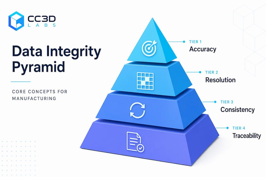
Before you can protect data integrity, you need a precise definition of what it includes. Four concepts form the foundation: accuracy, resolution, consistency, and traceability. Most professionals use the first two interchangeably, and that habit costs time and money.

Accuracy vs. resolution

Resolution and accuracy serve fundamentally different functions. Resolution describes how much surface detail the scanner captures. Accuracy describes how close those captured dimensions are to the physical truth of the object. A scanner can produce a beautifully detailed mesh at 0.05 mm point spacing that still carries a 0.3 mm dimensional error. In a product development workflow, the detail impresses stakeholders during review. The dimensional error shows up as a misfit during assembly.

High resolution also carries a practical cost. Excessive point density inflates file size, bogs down mesh repair, and slows every downstream process from CAD alignment to slicing. Matching resolution to intended use is not a compromise. It is the correct engineering decision.

Technician repairing scan mesh at lab bench

Consistency and traceability

Infographic pyramid showing scan data integrity concepts

Reliable scan data depends on repeatability, not just one good result. If scanning the same part twice under identical conditions produces meaningfully different outputs, nothing in your workflow is defensible. Consistency lets you trust comparisons, revisions, and inspection sign-offs.

Traceability ties your scan results to a verifiable standard. Calibrated reference artifacts, documented scan settings, and formal quality reports are what transform a point cloud from a visual deliverable into a manufacturing document. Consider the difference between a scan submitted to a contract manufacturer alongside a formal quality report that documents control points, outlier handling, and calibration history versus one submitted without any of that context. The first one gets approved. The second one gets questions.

  • Accuracy: Dimensional closeness to the physical object, measured against traceable standards
  • Resolution: Point density and surface detail, which should be matched to the specific use case
  • Consistency: Repeatability across sessions, operators, and equipment states
  • Traceability: Documentation linking scan results to calibrated standards and documented procedures

Together, these four elements define what strong 3D scanning data reliability actually looks like in practice.

Common threats to scan data integrity

Understanding the risks is not about pessimism. It is about knowing exactly where to focus your attention. Data integrity in 3D scanning is an emergent property, meaning it arises from multiple interacting layers rather than from any single component. When vulnerabilities in those layers align, even a capable scanner produces flawed data. This is the Swiss-cheese model applied to metrology workflows.

Here are the most common sources of failure, ranked by how often they are overlooked:

  1. Environmental conditions. Temperature, lighting, and vibration are the most underestimated threats to scan accuracy. Thermal expansion in a part being scanned in a warm production floor can shift dimensions measurably between the start and end of a single scan session. Air temperature gradients create measurement drift that no post-processing step can fully undo.

  2. Operator technique. The scanning path, standoff distance, overlap between passes, and handling of reflective or dark surfaces all introduce variability. Two operators scanning the same part with the same scanner can produce outputs that differ by more than the printed tolerance on the drawing.

  3. Hardware calibration drift. Sensors drift. Mechanical components develop play. A scanner that produced accurate results six months ago may no longer meet its stated specifications if calibration has not been maintained. This is particularly dangerous because the data often looks normal while carrying hidden dimensional errors.

  4. Software processing errors. Registration algorithms, mesh smoothing filters, and hole-filling routines all make decisions that affect dimensional truth. Default settings are not optimized for every geometry or material. Blindly applying them without understanding the tradeoffs is a common source of data degradation.

  5. Multiple interacting failures. The Swiss-cheese model predicts that single layers of defense rarely fail catastrophically on their own. An error in any one area is manageable. When poor environmental control, a drift-affected sensor, and aggressive mesh smoothing align in the same workflow, the result is data that looks clean but fails downstream.

Pro Tip: Before a major scan session, run a reference artifact through your full workflow, from capture to processed mesh. If the output falls outside your expected tolerance range, stop and find the cause before scanning the actual part.

Best practices to protect and maintain data quality

Knowing the threats is useful. Having a system to counter them is what actually protects your data. Reliability is a system-level outcome driven by calibration, environment, operator discipline, and software controls working together. No single action is enough on its own.

Calibration and traceable standards

Calibrate your scanner on a scheduled basis using certified reference artifacts. Document every calibration event with date, environmental conditions, and results. This documentation is what makes your data defensible for manufacturing acceptance in contract environments.

Modern metrology-grade scanners in 2026 can achieve volumetric accuracy of 0.03 mm + 0.05 mm per meter using multi-line laser modes, but that performance is only realized when calibration is current and conditions are controlled.

Hardware selection and environment control

Factor What to prioritize What to avoid
Scanner grade Metrology or industrial grade with stable housing Consumer devices for tight-tolerance work
Connectivity Onboard processing with dual Wi-Fi to prevent data loss Wireless setups that stream raw packets without error correction
Environment Temperature-controlled, vibration-dampened, diffuse lighting Bright window light, HVAC drafts, concrete floors near heavy machinery
Surface prep Matte reference spray or targets for reflective/dark surfaces Relying on raw surface appearance without preparation

Software and post-processing controls

Do not treat post-processing as cleanup. Every filter and alignment decision is a data modification. Use the minimum smoothing necessary for your application. Document the processing settings applied to each dataset. For high-quality manufacturing scans, the goal is mesh fidelity to the physical object, not visual appeal.

Pro Tip: Save both the raw point cloud and the processed mesh as separate files. If an alignment or filtering decision turns out to be wrong during CAD review, you can reprocess from raw data without rescanning the part.

  • Align scans using physical reference targets, not just software-generated feature matching
  • Run mesh quality checks before exporting, including hole counts, intersecting faces, and non-manifold edges
  • Match your export format and polygon count to what the downstream tool actually needs

The business impact of accurate scan data

The significance of 3D data integrity becomes clearest when you trace it directly to project outcomes. Reliable scan data reduces costly downstream failures and builds confidence in every decision that follows the scan. That effect compounds quickly in iterative product development.

Consider a typical reverse engineering project. A product team scans an existing component to create a replacement part. If the scan carries a 0.2 mm accuracy error and the designer does not detect it, the CAD model inherits that error. The prototype is printed or machined to that incorrect model. The fit test fails. The team scans again, remodels, reprints. Each cycle costs time and materials. The root cause was never the printing or machining. It was the scan data.

The importance of 3D scan accuracy is equally clear in inspection workflows. When scan data is traceable and consistent, it serves as a legal and contractual record of part geometry at a specific point in time. That record supports quality sign-offs, warranty claims, and deviation approvals with documented evidence rather than verbal assurance.

  • Accurate scan data cuts the number of prototype iterations by giving designers a reliable baseline to work from
  • Clean, well-structured mesh files reduce prep time in CAD and slicing software, directly lowering labor costs per part
  • Traceability documentation supports ISO and AS9100 quality requirements, which matter in aerospace, medical, and automotive supply chains
  • Consistent data across scan sessions makes it possible to detect genuine part wear or tooling drift, rather than noise from scan variability

For teams doing rapid prototyping, the benefits of accurate 3D scans are not abstract. They show up in the number of design cycles completed per week, the scrap rate on first-article inspection, and the speed of design sign-off. Those are the metrics that determine project profitability.

My take on where most teams go wrong

I have reviewed a lot of 3D scanning workflows over the years, and the pattern that frustrates me most is not carelessness. It is misplaced focus. Teams spend considerable money on a premium scanner and then operate it in conditions that undermine every advantage the hardware offers. The scanner becomes a status symbol rather than a calibrated instrument.

The misconception I run into most often is that a higher price tag or a more impressive spec sheet guarantees better data. It does not. A well-operated mid-range scanner in a controlled environment with a disciplined operator consistently outperforms a metrology-grade instrument scanned on a vibrating factory floor by someone who has not been trained on the specific geometry they are capturing.

What I have learned from working through enough failed prototypes is that workflow discipline matters more than any single tool upgrade. Calibration schedules, environmental logs, processing documentation, and reference artifacts are unglamorous. They do not appear in marketing materials. But they are the actual mechanism by which good data gets produced reliably, not occasionally.

My honest recommendation is to build your scanning protocol before you buy your next scanner. Understand exactly what the workflow demands in terms of accuracy, consistency, and traceability. Then select hardware that fits that protocol. The teams that do this consistently produce better outcomes than teams chasing the highest-spec device without a system around it.

— Justin

Get reliable scan data with Cc3dlabs

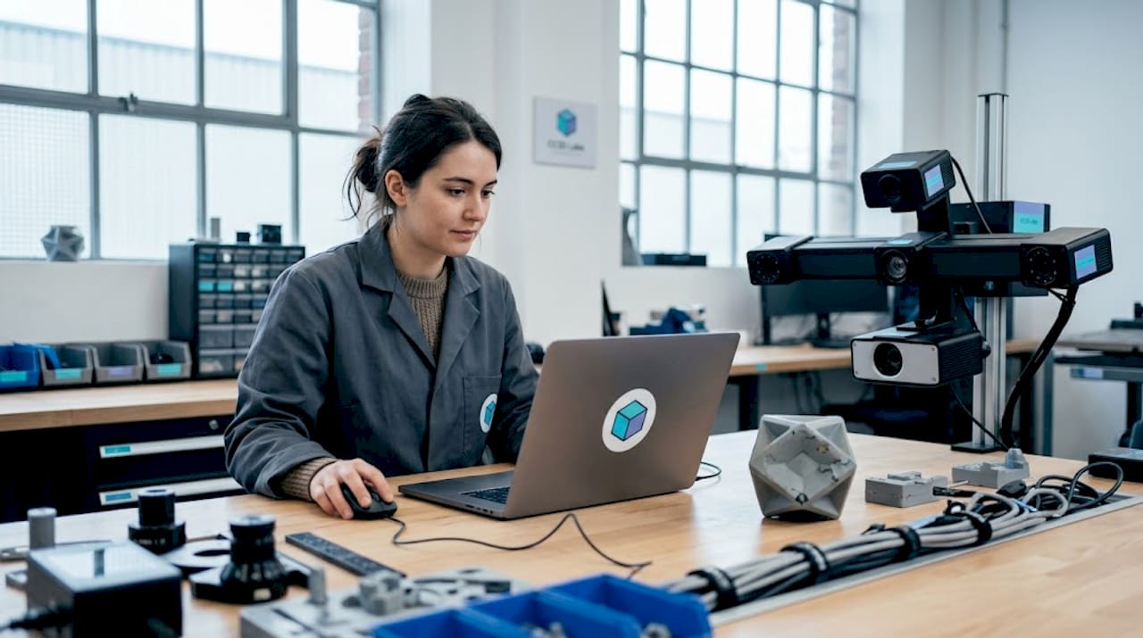
If this article has clarified what 3D scan data integrity actually requires, the logical next step is working with a team that applies these principles on every project. Cc3dlabs provides metrology-grade 3D scanning services from our facility near Philadelphia, and data quality is built into the workflow, not treated as an afterthought. Every scan includes calibration verification, documented processing steps, and output quality checks designed to support prototyping and manufacturing use.

https://cc3dlabs.com

Whether you are reverse engineering an existing component, inspecting a manufactured part, or generating scan data for a new prototype, our 3D scanning and prototyping guide walks you through how we approach accuracy and reliability at each stage. For hands-on preparation before your next scan session, the scanning accuracy checklist covers the specific steps that prevent the most common sources of data degradation. When you are ready to move from scanning to production, our full printing and prototyping services handle everything from single prototypes to batch production runs with the same commitment to dimensional accuracy.

FAQ

What does 3D scan data integrity actually mean?

Data integrity in 3D scanning means the captured data accurately and consistently represents the physical object with traceable, documented quality. It covers accuracy, repeatability, and the controls used during capture and processing.

How is accuracy different from resolution in 3D scanning?

Accuracy measures dimensional closeness to the real object, while resolution measures how much surface detail is captured. A high-resolution scan can still contain significant accuracy errors that cause problems in manufacturing.

What are the biggest threats to scan data quality?

Environmental factors like temperature and vibration, calibration drift, operator technique, and uncritical post-processing are the most common causes of data degradation, and they interact to compound errors.

How do I know if my scan data is good enough for manufacturing?

Run the processed mesh through a dimensional comparison against a calibrated reference artifact, check mesh quality metrics including non-manifold edges and holes, and document the calibration state of your scanner at the time of capture.

Why does 3D scanning data reliability matter for prototyping?

Unreliable scan data propagates errors into every downstream step, from CAD modeling to print or machining. Catching and correcting those errors at the source saves multiple prototype cycles and the costs that come with them.

Engineer checking CAD model for optimization

The 3D Part Optimization Process for Engineers


TL;DR:

  • Engineers often overlook that proper part orientation, wall count, and design choices significantly improve strength and reduce support needs. Focusing on defining requirements before slicing ensures optimal geometry, load paths, and fit, minimizing material waste and print time. Validating mating interfaces with small test prints early can prevent costly reprints and streamline production.

Every engineer who has pulled a brittle, support-crusted print off the bed and thought “this should have worked” knows the real cost of skipping the 3d part optimization process. Poor orientation choices, default infill settings, and designs that weren’t built with additive manufacturing in mind waste filament, machine time, and development cycles. The good news: optimization isn’t guesswork. It’s a structured sequence of decisions that starts before you touch your slicer and ends only after you’ve validated the finished part. This guide walks you through that sequence, step by step.

Table of Contents

Key takeaways

Point Details
Start with requirements, not settings Define load paths, fit requirements, and production volume before opening your slicer.
Orientation beats infill for strength Aligning loads parallel to layer lines delivers more strength per gram than chasing high infill percentages.
Walls drive structural performance Increasing perimeter count from 2-3 to 4-6 can dramatically improve tensile strength with minimal added print time.
Design out supports early Chamfers, 45° self-supporting angles, and split-part strategies reduce material waste before printing begins.
Validate interfaces before full runs Printing only critical mating sections first catches fit issues early and protects your full material budget.

The 3D part optimization process starts with requirements

Before you adjust a single slicer setting, you need to know exactly what the part has to do. That sounds obvious, but a surprising number of optimization failures trace back to this step being skipped or treated superficially.

Ask four questions about every part you intend to print:

  • What loads will it carry? Tensile, compressive, torsional, impact? Each favors different orientation and material choices.
  • Does it mate with anything? Threads, press fits, snap fits, and sliding interfaces all require tight tolerance control that must be planned, not fixed in post-processing.
  • What’s the surface finish requirement? A cosmetic panel and a functional bracket can share the same material but need completely different layer heights and orientation decisions.
  • How many are you producing? A single prototype tolerates extra support and slower speeds. A batch of 200 functional parts does not.

Understanding these requirements directly shapes your decisions about part orientation, wall strategy, and infill density in every phase that follows. This integrated thinking across design and settings is what separates a deliberate optimization process from random trial and error.

Design for additive manufacturing principles apply here too. The most effective way to reduce supports is to design a part that doesn’t need them. Self-supporting geometry relies on keeping overhangs at or below 45° from vertical. Steeper angles require support material, which adds print time, wastes filament, and often leaves surface artifacts where the support contacted the part. When a feature requires a steep overhang, replacing it with a chamfer or splitting the part into two printable sections is almost always the better call. If you’re still developing your design workflow for manufacturing, locking in these principles at the modeling stage pays dividends across every print you run.

Pro Tip: When designing for batch production, model your split lines and chamfers as first-class design decisions, not afterthoughts. A five-minute geometry change during CAD can eliminate 40 minutes of support removal per unit.

Infographic shows 3D part optimization workflow

Execution phase 1: print settings that actually build strength

Once your design respects the geometry rules, your slicer decisions determine whether the part meets its mechanical targets. The priority order here matters more than most engineers expect.

  1. Set orientation first. Parts are strongest along the X-Y plane because FDM materials exhibit layer anisotropy. Loads applied parallel to the layer plane are resisted by the full cross-section of the material. Loads applied perpendicular to layers rely on interlayer adhesion, which is the weakest bond in any FDM part. Orient the part so your primary load path runs parallel to the print bed whenever geometry allows.

  2. Choose nozzle size based on the part’s demands. A 0.4mm nozzle is a reasonable default, but it isn’t always right. Coarse structural parts with no fine features print faster and often stronger through a 0.6mm or 0.8mm nozzle because thicker extrusions bond better. Fine detail parts may need a 0.2mm nozzle. Choosing the wrong nozzle size means you’re either wasting time or sacrificing resolution you didn’t need to sacrifice.

  3. Prioritize walls over infill. This is where most engineers leave performance on the table. The priority decision-stack treats infill as supplemental, not structural. Infill supports the shell and transfers minor loads between walls. The walls themselves are load-bearing. Increasing perimeters from 2-3 to 4-6 can roughly double tensile strength with a fraction of the material cost that the same result would take with infill alone.

  4. Set layer height based on finish and throughput needs. Thinner layers improve surface quality and bonding at a cost of print time. Thicker layers print faster with slightly reduced Z-direction resolution. For structural parts where finish matters less, 0.2mm to 0.3mm is a solid range. For cosmetic or precision-fit surfaces, 0.1mm to 0.15mm is worth the added time.

  5. Dial in extrusion width and print speed together. Slightly over-extruding, setting extrusion width to 110-120% of nozzle diameter, improves layer bonding significantly. Pair that with conservative print speeds on outer walls and you get noticeably better surface finish without changing any material or hardware.

Pro Tip: Print your structural outer walls at 50-60% of your standard print speed. The inner walls and infill can run fast. The outer wall bond quality is what you’ll feel when you load the part.

If you want a consolidated view of how to reduce print costs without sacrificing mechanical performance, the relationship between wall count and infill is a good place to start.

Technician adjusting 3D printer in workspace

Execution phase 2: cutting supports and controlling fit

Support material is the single most expensive line item in many print budgets. You pay for it in filament, print time, and post-processing labor. The goal of the 3d printing optimization process at this stage is to minimize supports through geometry choices, not just slicer settings.

Key tactics to reduce support usage:

  • Replace any overhang steeper than 45° with a chamfer or stepped feature. Avoiding steep overhangs by design eliminates support needs at the source, which is far more material-efficient than generating supports and then removing them.
  • Split complex parts along natural support-free planes and bond or fasten them after printing. Two clean parts printed without support often outperform one supported print both mechanically and dimensionally.
  • Use slicer-level support controls as a last resort. Adjusting support overhang thresholds, interface layers, and Z-distance can reduce support volume and ease removal, but these are refinements to a design problem, not solutions.

Dimensional accuracy requires its own set of deliberate choices. Press fits and snap fits are particularly unforgiving. The standard approach of modeling a hole at nominal diameter and hoping the printer hits it rarely works without calibration. You need to run a calibration print for your specific material and temperature combination and capture your actual shrinkage coefficient before committing to tolerance-critical dimensions.

Pro Tip: For any part with a mating interface, print just the mating zone as a standalone test piece before running the full part. This fit-check approach uses under 3g of filament and roughly 30 minutes of print time to verify whether your tolerance assumptions are correct. It will save you full reprints.

Verification phase: test, adjust, and lock in

The 3d part optimization process does not end when the print finishes. A part that looks correct can still fail under load, exhibit unexpected surface artifacts, or refuse to mate with its counterpart. Verification is where you close that gap between what you designed and what the printer produced.

Follow this sequence for each new part or revised iteration:

  1. Print mating-section test pieces first. Fit-check prints isolate interface risk before you commit filament to the complete part.
  2. Evaluate the test piece dimensionally and functionally. Measure the actual feature dimensions against nominal. Check clearance, press force, snap engagement, or whatever the fit requirement specifies.
  3. Adjust tolerances in the model or slicer based on measured deviations. A 0.1mm to 0.2mm compensation is common for most FDM setups.
  4. Print the full part and evaluate strength and surface finish against your original functional requirements.
  5. Apply post-processing where the part still falls short. Annealing improves crystalline polymer strength. Epoxy coating improves surface hardness and moisture resistance. Sanding or chemical smoothing addresses cosmetic finish.

The table below summarizes what to adjust based on common verification failures:

Failure Mode Likely Cause Adjustment
Part fractures under load Weak layer adhesion or poor orientation Reorient load path, increase wall count, reduce print speed
Mating interface too tight Insufficient tolerance compensation Add 0.1-0.2mm clearance to hole features
Mating interface too loose Over-compensated tolerances Reduce clearance offset, recheck calibration
Poor surface finish on top layers Inadequate top layer count Increase top solid layers to 5-6
Warping or delamination Cooling or adhesion issues Reduce cooling fan speed, increase bed temperature

For low-volume production, this iteration cycle often runs two to three times before settings are locked. For scaled manufacturing runs, the investment in that early iteration cycle pays back in reduced scrap rates across every subsequent print.

What I’ve learned after watching engineers skip these steps

In my experience working on functional print projects, the single most consistent mistake I see product developers make is treating infill as the primary strength lever. They see a weak part and immediately bump infill from 20% to 60%. That consumes significantly more material and adds print time, but delivers far less strength improvement than simply adding two perimeter walls would have.

I’ve watched teams spend days reprinting support-heavy assemblies because the support geometry was never questioned at the design stage. A split-part strategy, something that would have taken an hour to model, would have eliminated the entire problem. The labor cost of support removal is rarely factored into part cost calculations, but it should be.

What I’ve found actually works is this: treat the first iteration of any new part as a learning print, not a production print. Print the mating sections, validate them, check your orientation against the load path, and then run the full part. That discipline, applied consistently, shortens development cycles more than any single settings trick. And early design validation before committing to full runs is the clearest signal I know that an engineering team is thinking about optimization the right way.

— Justin

Get expert support for your optimization workflow

https://cc3dlabs.com

If you’re working through a print optimization challenge and want experienced support behind your production process, Cc3dlabs is built for exactly that. Located near Philadelphia, Cc3dlabs provides precision printing and design support for product developers and engineers running prototypes, functional parts, and batch production orders. Their team handles orientation strategy, tolerance validation, and material selection as part of every project, so your parts arrive ready to function, not just ready to look at. From on-demand part production to metrology-grade 3D scanning for fit verification, Cc3dlabs offers the technical depth that turns optimization principles into consistent, repeatable results.

FAQ

What is the first step in the 3D part optimization process?

Define your functional requirements before touching your slicer. Understanding load paths, fit requirements, surface finish needs, and production volume shapes every orientation and settings decision that follows.

Does infill percentage affect part strength more than wall count?

No. Wall count dominates strength per unit of material in FDM parts. Increasing perimeters from 2-3 to 4-6 delivers significantly more tensile strength than equivalent infill increases, with less added filament.

How do I reduce support material when optimizing printed parts?

Design out supports by keeping overhangs at or below 45° and using chamfers or split-part strategies in your CAD model. Support avoidance by design is consistently more material-efficient than generating and removing supports after printing.

How should I validate fit before committing to a full print run?

Use your slicer to isolate and print only the mating-interface section of the part first. These fit-check test pieces use minimal filament and print quickly, letting you verify tolerance accuracy before running the complete part.

Why does part orientation matter so much in 3D printing optimization?

FDM parts are anisotropic. Strength along the X-Y plane is significantly higher than across layer boundaries. Orienting the part so primary loads run parallel to layers is one of the highest-return decisions in the entire optimization process.

Maker prepping multi-color FDM print in workspace

How to Create Multi-Color Prints: FDM Creator’s Guide


TL;DR:

  • Multi-color 3D printing in FDM requires matching techniques to specific hardware types, from manual filament swaps to multi-toolhead systems. Software like PrusaSlicer supports color assignment and preview, enabling effective control over complex multi-color models. Advanced systems such as the MMU3 and multi-toolhead printers offer higher fidelity and lower waste, but manual swaps remain accessible for simpler projects.

Multi-color 3D printing is one of the most exciting capabilities in FDM printing today, but getting it right takes more than just loading a colorful filament. If you want to know how to create multi-color prints that actually look sharp, you need to understand which workflow matches your hardware, how slicers handle color assignment, and where most creators go wrong. This guide walks you through every major approach, from simple manual filament swaps on a single-extruder machine all the way up to multi-toolhead systems, with practical tips at every level.

Table of Contents

Key Takeaways

Point Details
Match method to hardware Your printer type determines which multi-color technique is actually achievable without modifications.
Use 3MF over STL STL files strip color data; 3MF format keeps color regions intact for clean slicer assignment.
Purge waste adds up fast Filament purging between color changes can exceed the volume of the model itself if not managed carefully.
MMU3 unlocks five colors per layer Multi-filament add-ons like the Prusa MMU3 allow true per-layer color mixing without manual pauses.
Slicer preview is non-negotiable Always verify filament assignments in slicer preview before sending a multi-color job to the printer.

How to create multi-color prints: tools and setup

Before you touch a slicer, you need the right hardware and software in place. The method you use to produce multi-color prints depends almost entirely on your printer setup.

Printer types for multi-color printing:

  • Single-extruder printers (e.g., Prusa MK4S): Support manual filament swaps between layers. Simple, low-cost, but limited to one color per layer at a time.
  • Multi-filament add-ons (e.g., Prusa MMU3): Attach to a single-extruder printer and automate filament switching, supporting up to five colors.
  • Multi-extruder or multi-toolhead printers (e.g., Prusa XL): Feature independent printheads per color, offering the cleanest transitions and lowest purge waste.

Software matters just as much as hardware. PrusaSlicer is the go-to option for most multi-color workflows because it supports model painting and color assignment using brushes and smart fill tools. BambuStudio offers similar functionality for Bambu hardware. Both let you preview filament assignments per object before printing.

For filament materials, PLA is the easiest starting point since it sticks well between layers and comes in hundreds of colors. PETG is a step up in durability. When mixing filament types across extruders, check compatibility first. Running PLA in one nozzle and TPU in another on the same layer can cause adhesion failures if temperature settings are not optimized.

Hardware Option Colors Possible Waste Level Best For
Single extruder + manual swap 2 to 6 (layer-based) Low Beginners, simple designs
MMU3 add-on Up to 5 per layer Medium Hobbyists, detailed models
Multi-toolhead (XL) Up to 5 per layer Low to medium Professionals, high fidelity
Multi-nozzle carousel systems 12+ colors Very low Advanced, specialized use

Pro Tip: Always slice your model at 100% scale before assigning colors. Re-scaling after color regions are painted in the slicer can shift assignments and create mismatches at boundaries.

The manual filament change method

The most accessible path to making colorful prints on any FDM printer is the manual filament swap method. You do not need any add-ons or extra hardware. What you do need is a slicer that supports color change markers and the patience to babysit the printer during the job.

Here is how to do it step by step:

  1. Prepare your model. Keep it simple for your first attempt. A flat logo or layered badge works perfectly because the color regions align naturally with horizontal layers.
  2. Set color change markers in your slicer. In PrusaSlicer, right-click on the layer preview timeline and add a “Color Change” marker at the exact layer height where you want the transition. The printer will pause and prompt you to swap filament. Manual color change automatically pauses at the specified layer.
  3. Swap the filament. When the printer pauses, unload the current filament, load the new color, and purge until the new color runs clean through the nozzle. Do not rush this step.
  4. Resume the print. Confirm the swap in the printer interface and watch the first few layers to confirm the color is correct before walking away.

Limitations to know upfront: The manual swap method cannot blend two colors within a single layer. Every color change applies to a full horizontal layer and above. That means complex multi-color graphics with side-by-side colors in the same layer are not achievable this way.

Pro Tip: Print a small purge block next to your model. It catches residual color bleed without contaminating your actual print, and you just discard it when done.

A few common mistakes to avoid:

  • Pulling the filament too fast during unload and leaving a clog at the nozzle tip
  • Not purging enough material before resuming, which causes color spotting on the first few layers of the new color
  • Forgetting to re-level the bed after a swap if the printer was bumped

Using multi-filament add-ons like the MMU3

When you want more than two or three colors without standing at the printer for hours, a multi-material unit changes everything. The Prusa MMU3 attaches to a compatible Prusa printer and manages automated filament loading and unloading across up to five spools.

How the MMU3 workflow works:

  • You load up to five filament spools into the MMU3 unit and thread them into the selector.
  • In PrusaSlicer, you paint different regions of your model with different filament assignments using the brush or smart fill tool.
  • During printing, the MMU3 unloads the active filament, selects the next one, and loads it into the nozzle automatically.
  • Purge material is deposited into a wipe tower printed alongside your model, using an efficient unload method similar to a cold pull to reduce waste.

The filament mapping UI in PrusaSlicer also lets you reassign which filament slot handles which model region. If a spool runs out mid-print, you can remap to a backup without starting over. That is a genuinely useful feature on longer jobs.

Feature MMU3 Manual Swap
Colors per layer Up to 5 1
Requires user intervention No Yes
Purge waste Medium (wipe tower) Low (manual purge)
Setup complexity Moderate Minimal
Best color separation Excellent Layer-level only

Managing the wipe tower is one of the bigger decisions in the MMU3 workflow. You can reduce its size in slicer settings, but go too small and you get color contamination between transitions. For most hobbyist projects, leaving the wipe tower at default settings and optimizing later is the right call.

Pro Tip: Group your color changes so that adjacent layers use the same filament as often as possible. Fewer actual switches per layer means a smaller wipe tower and faster print times.

Advanced multi-toolhead and multi-nozzle systems

Multi-toolhead printers represent the highest level of multi-color printing available to creators today. Instead of routing different filaments through a single nozzle (which always requires purging), these machines physically swap the entire printhead for each color.

Technician working with multi-toolhead 3D printer

The Prusa XL toolchanger supports up to five independent tool heads, each with its own extruder and nozzle. When a color switch is needed, the printer docks the current head and picks up the next one. Because no filament residue remains in a shared nozzle, the wipe tower shrinks dramatically and color fidelity improves.

Even further along the spectrum are carousel-style multi-nozzle systems. A 12-nozzle rotating printer cuts the filament and rotates a new nozzle into position rather than purging, which nearly eliminates purge waste entirely. This approach solves one of the most persistent pain points in multi-color FDM printing.

Advantages of multi-toolhead systems:

  • True per-layer color placement with no bleed between regions
  • Different nozzle sizes per tool head (detail nozzle for fine color work, larger nozzle for structural infill)
  • Support for mixed materials in a single print, such as flexible TPU alongside rigid PLA
  • Lower filament waste than MMU-style systems on complex multi-color models

The tradeoff is cost and footprint. The Prusa XL costs several times more than a standard MK4S. For a hobbyist running occasional multi-color projects, the MMU3 add-on delivers strong results at a fraction of the price. For creators producing high-detail multi-color work regularly, or running batch multi-color jobs, a toolchanger system pays off quickly in time and material savings.

Troubleshooting common multi-color print problems

Even with a solid setup, multi-color prints introduce failure modes that single-color jobs never surface. Here is how to address the most common ones.

Color bleeding between regions is the most frustrating issue. It usually means your wipe tower is too small, your purge volume is too low, or your retraction settings are not tuned. Increase the wipe tower width in slicer settings by 10mm increments and re-test until transitions run clean.

Filament misloads with MMU systems often happen when you mix pause-based color swaps with object-based painting in the same print job. Verify your slicer preview carefully before printing and avoid combining both methods in a single file.

File format matters more than most creators realize. The STL format lacks color data, which means every color assignment has to be done manually in the slicer after import. A 3MF file, by contrast, carries color region assignments directly. If you are designing your own multi-color model, export from your CAD software as a multi-body 3MF where each color is a separate object. It saves a significant amount of setup time.

Pro Tip: Tools like MosaicFlow use AI to separate color regions from an uploaded image and export a ready-to-slice 3MF file. For creators who want to turn artwork or logos into multi-color prints quickly, this shortcut is worth knowing.

For anyone dealing with purge waste exceeding model volume, the first fix is reducing unnecessary color switches. Review your slicer’s layer preview and consolidate layers where the color change order does not affect appearance. Every eliminated switch saves filament and print time.

File preparation and slicer settings are where most multi-color prints are won or lost. The printer does exactly what the G-code tells it to.

My take on where multi-color printing actually stands

I’ve worked hands-on with multi-color FDM setups across the spectrum, from basic layer swaps to full toolchanger systems, and my honest view is that we are in a genuinely interesting period for this technology.

The manual filament swap method gets a lot of dismissal, but I think it is underrated for specific use cases. If you want a clean two-tone or three-tone print and you are not in a hurry, it produces surprisingly sharp results with zero additional hardware investment. The limitations are real, but so is the simplicity.

What I’ve learned about MMU-style systems is that patience with setup pays dividends later. The first time I dialed in a wipe tower and filament mapping on a complex five-color badge print, I spent three hours on prep and ten minutes on the actual print. That ratio flips fast once the workflow clicks.

The biggest shift I’ve seen recently is software catching up to hardware. The multi-color 3D printing methods available now are genuinely more accessible than they were two years ago, largely because slicers have gotten smarter about color assignment and waste reduction. The hardware innovations are exciting, but software is what makes them usable for everyday creators.

My advice: start with manual swaps to understand how color transitions work physically, then graduate to an MMU-style add-on when you want automation. Only invest in a toolchanger system if multi-color printing is a core part of your workflow, not an occasional experiment.

— Justin

Take your multi-color prints further with Cc3dlabs

If you have pushed your home setup as far as it goes and want genuinely professional results, Cc3dlabs is the next step worth considering.

https://cc3dlabs.com

Cc3dlabs operates near Philadelphia and specializes in professional multi-color printing for creators, product developers, and businesses. Their team works with advanced multi-filament FDM systems to produce high-fidelity color prints across prototypes, display models, and functional parts. Whether you need a single detailed prototype or a production batch, Cc3dlabs handles the file prep, material selection, and print execution so you get clean, repeatable results without the learning curve. Get a free online estimate through their 3D printing services page, and see what professional-grade multi-color capability actually looks like.

FAQ

What are multi-color prints in 3D printing?

Multi-color prints are FDM 3D printed objects that incorporate two or more filament colors in a single model. They are produced through manual filament swaps, multi-filament add-ons, or multi-toolhead printers depending on the desired complexity.

Can any FDM printer make multi-color prints?

Yes. Any FDM printer can produce basic multi-color prints using manual filament changes at specified layer heights. For per-layer color placement and more than two colors, a multi-filament add-on or multi-extruder system is required.

How do I reduce waste when printing in multiple colors?

Minimize the number of color switches per layer, increase wipe tower efficiency in your slicer, and consider a toolchanger system for high-color-count jobs, since purge waste can exceed model volume in standard MMU setups.

Infographic steps to reduce waste in multi-color prints

What file format works best for multi-color 3D printing?

3MF is the preferred format because it retains color region assignments that STL files cannot store. Designing multi-body models where each color is a separate object makes slicer color assignment much faster and more accurate.

How many colors can I print at once with FDM?

Manual filament swaps support as many colors as you are willing to swap, but only one color per layer. The Prusa MMU3 supports up to five colors simultaneously per layer, while advanced carousel nozzle systems can handle twelve or more.

Woman removing supports from 3D print at workbench

What Is Post-Processing in 3D Printing and Why It Matters


TL;DR:

  • Post-processing in 3D printing includes support removal, cleaning, curing, sanding, and surface treatments that determine part functionality and appearance. It is essential for achieving professional quality, mechanical strength, and compliance with industrial standards, especially for metal or high-stakes components. Properly matching techniques to end-use and planning sequences early optimizes results and reduces errors in additive manufacturing.

Most people assume the hard work ends when the print finishes. It doesn’t. What is post-processing in 3D printing? It’s every step you take after the printer stops: removing supports, cleaning away residue, sanding surfaces, applying coatings, or running parts through advanced finishing treatments. These steps determine whether your print is a rough prototype or a production-ready component. Skip them, and even a technically perfect print can fail a fit test, look unprofessional, or break under load. Master them, and you unlock the full potential of additive manufacturing.

Table of Contents

Key Takeaways

Point Details
Post-processing defines final quality The printing process creates geometry, but finishing determines whether a part is functional and presentable.
Core steps apply across technologies Cleaning, support removal, and curing are foundational regardless of whether you use FDM, SLS, or resin printing.
Surface finishing changes mechanics Spray painting and sanding affect not just appearance but also hardness, roughness, and dimensional accuracy.
Advanced methods meet industrial standards Metal parts often require electro-polishing, laser treatment, or plating to satisfy aerospace and medical certifications.
Match technique to end-use A visual prototype needs different finishing than a load-bearing functional part. Knowing the difference saves time and money.

What is post-processing in 3D printing: the fundamentals

Before you decide which finishing method to use, you need to understand the three foundational steps that apply to almost every print technology. These aren’t optional. They’re where you prepare the part for any further work.

Support removal and cleaning

Support structures are temporary scaffolding. For FDM prints, you typically snap or cut them away with flush cutters and pliers. For resin prints, you dissolve or peel them off after washing the part in isopropyl alcohol. The material matters here. Water-soluble PVA supports can simply dissolve in water when used with dual-extrusion FDM printers, which is a genuine convenience for complex geometries.

Cleaning is equally non-negotiable. Resin prints must be washed to remove uncured liquid resin before UV curing. SLS powder-bed prints are covered in semi-sintered powder that has to be removed before any other step. Automated media blasting can reduce SLS cleaning time to as little as 5 minutes, compared to the labor-intensive brushing that used to be standard. And for parts with complex cavities, automated blasting cleans negative features that a brush simply cannot reach.

Curing for resin-based prints

UV curing is mandatory for any photopolymer print. Without it, the part remains brittle, sticky, and chemically unstable. Most desktop users cure parts in a dedicated UV curing station for 2 to 15 minutes depending on part thickness and resin type. Industrial setups use calibrated UV ovens with temperature control to achieve consistent mechanical properties across a production batch.

Man curing resin 3D print in UV chamber

Pro Tip: After curing a resin part, let it cool completely before handling. Warm resin is softer and more prone to warping under pressure from your fingers.

Surface finishing techniques and their trade-offs

Once your part is clean and structurally stable, surface finishing determines how it looks and how it performs. This is where the role of post-processing in 3D prints becomes most visible, and most consequential.

Sanding and mechanical polishing

Sanding is the most accessible 3D printing finishing method available. You start with a coarse grit (around 120 to 200) to knock down layer lines, then work progressively toward finer grits (400, 800, 2000) for a smooth surface. For tight geometries or internal channels, flexible sanding sticks or rotary tools work better than flat sandpaper.

Mechanical polishing with a buffing compound after wet sanding can bring FDM parts to an almost glass-like finish. This works particularly well on PETG and ABS. The trade-off: sanding removes material, so if your part has tight tolerances, you need to account for that. To understand how dimensional accuracy interacts with prototype reliability, it’s worth thinking about finishing from the design stage, not after the fact.

Chemical smoothing

Acetone vapor smoothing is the most well-known chemical finishing method for ABS parts. You expose the part to acetone vapor in a controlled container, and the solvent melts the surface layer just enough to flow and fuse the layer lines. The result looks injection-molded. The downside is real: acetone vapor smoothing reduces roughness but softens the material, which can compromise tensile strength and dimensional accuracy.

For PLA, tetrahydrofuran (THF) or ethyl acetate can produce similar effects, though they require careful handling due to toxicity. These chemical approaches are best reserved for appearance models, not load-bearing parts.

Coatings and painting

Painting is underrated as a finishing technique, particularly when you look at the numbers. Spray painting ABS parts reduces surface roughness by 70% and increases hardness by 19%, outperforming acetone dipping and copper sputtering in surface quality improvement. The key is surface preparation: primer first, then two or three light coats, with light sanding between layers.

Infographic showing five steps of post-processing

Finishing method Roughness reduction Effect on hardness Best for
Spray painting ~70% +19% Aesthetics and light mechanical improvement
Acetone vapor (ABS) Significant Slight decrease Visual models only
Sanding (manual) Moderate No direct effect Any material, tight tolerance parts
Shot blasting (metal) 62% to 70% Varies Metal MEX parts

Pro Tip: Apply a UV-resistant clear coat as your final layer on any painted or primed exterior part. It prevents yellowing and surface degradation when the part is used outdoors or under shop lighting.

Advanced post-processing for metal and industrial parts

When you move into metal additive manufacturing or parts destined for aerospace, biomedical, or heavy industrial applications, the types of 3D printing post-processing required change substantially. The stakes are higher, and so are the methods.

Electro-polishing, chem-polishing, and plating

For stainless steel parts produced by laser powder bed fusion or material extrusion, a multi-stage finishing sequence delivers the best results. Combining chemical polishing, electro-polishing, and electroless nickel plating maximizes surface finish and mechanical durability. The optimal sequence is chemical polishing first, then electro-polishing, then electroless nickel plating. Each stage builds on the previous one.

Electroless nickel plating specifically improves corrosion resistance, wear resistance, and surface hardness on AM stainless steel parts. Getting the process parameters right matters: bath temperature, pH, and immersion time all affect coating uniformity and adhesion. This level of finishing is why certain additively manufactured components can pass requirements that were previously only achievable through subtractive machining.

Laser-based surface modification

Laser treatments are among the most precise post-processing techniques available. Laser polishing uses controlled surface melting to smooth surface asperities while maintaining dimensional fidelity. Laser shock peening takes a different approach: it induces compressive residual stresses in the surface to improve fatigue life without adding heat to the bulk of the part.

These techniques matter because post-processing greatly influences fatigue life, corrosion resistance, and dimensional precision of metal parts. Minor surface imperfections can reduce durability significantly when a part cycles through stress millions of times. Shot blasting on metal MEX parts has shown roughness reductions of 62% to 70% on lateral surfaces. That’s not cosmetic. That’s structural.

Regulatory standards and qualification

Post-processing for high-stakes applications isn’t just about performance. It’s about documentation and compliance. Post-processing choices critically impact part certification, requiring rigorous validation protocols especially in aerospace and medical sectors. ASTM and NASA standards define acceptable surface conditions, and hybrid finishing processes often require custom validation plans to demonstrate durability under fatigue, corrosion, and wear conditions.

For manufacturers navigating these requirements, understanding part validation in 3D printing is not optional. You need traceability, documented process parameters, and test results that prove each post-processing stage contributed to the final mechanical specification.

Choosing the right post-processing approach

The benefits of post-processing are only realized when you match the method to the goal. Here’s how to think through that decision systematically.

  1. Define the end-use first. Post-processing method selection should be driven by whether the goal is visual prototyping or mechanical testing. A concept model shown at a client meeting needs a smooth, painted surface. A functional bracket needs dimensional accuracy and structural integrity. Conflating these goals leads to over-processing or under-processing.

  2. Match finishing to material. PLA is difficult to chemically smooth and doesn’t respond well to acetone. ABS is ideal for vapor smoothing but softens if over-treated. Resin requires UV curing before any mechanical finishing. Metal parts need abrasive or electrochemical treatments that plastics never require.

  3. Plan your sequence before you start. The order of operations matters. For a painted FDM part, the correct sequence is: support removal, sanding (coarse to fine), primer coat, light sanding, color coat, clear coat. Skipping primer leads to paint adhesion failures. Skipping coarse sanding before primer wastes fine coats on a rough substrate.

  4. Consider the tolerance budget. Every finishing step removes or adds material. If your part has a 0.1 mm press-fit tolerance, track how much material each step removes. Sanding, vapor smoothing, and coating all affect final dimensions. Build this into your 3D print design workflow from the start.

  5. Prototype your finishing process. Before committing a final production run to a new post-processing sequence, run the process on a test print. This is especially true for chemical treatments and coatings on unfamiliar materials.

Pro Tip: When working with resin parts that will be sanded and painted, cure them at least 30% longer than the manufacturer’s recommended time. A fully cured part sands more cleanly and holds primer without micro-chipping.

My honest take on post-processing

I’ve seen people spend weeks perfecting their print settings and then rush the finishing in an afternoon. That’s backwards. In my experience, the finishing stage regularly accounts for 40 to 60 percent of the time it takes to produce a high-quality, presentation-ready part. The printing is the easy part now. The finishing is where skill actually shows.

What surprises most people I work with is that post-processing isn’t just about aesthetics. I’ve watched parts that looked perfect off the printer fail fatigue tests because the surface condition was inconsistent. The research is clear on this: surface region condition is decisive for long-term durability. That’s not an abstract concern for aerospace engineers. It applies to any functional part that will see repeated stress.

The other thing I’d push back on is the idea that more finishing is always better. I’ve seen parts chemically smoothed into dimensional failure. I’ve seen coatings applied so thickly that mating surfaces no longer fit. Choosing the right print type from the beginning reduces how much corrective finishing you need later. Post-processing is powerful, but it isn’t a fix for poor design decisions or the wrong material choice.

My advice: treat finishing as part of the design process, not an afterthought. Know what your part needs before the print even starts.

— Justin

Let Cc3dlabs handle the finish work

https://cc3dlabs.com

At Cc3dlabs, near Philadelphia, post-processing isn’t something we bolt on at the end. It’s built into every project from the start. Whether you’re working with filament-based prototypes that need a clean, professional surface or functional parts that require consistent dimensional accuracy across a batch, our team applies the right finishing methods for the job. We handle diverse materials, manage tight tolerances, and support clients from single-part prototyping through production-scale orders. Explore our professional 3D printing services to see how we integrate finishing into every part we deliver, locally or shipped anywhere.

FAQ

What does post-processing mean in 3D printing?

Post-processing in 3D printing refers to all steps performed after a part is printed, including support removal, cleaning, curing, sanding, painting, and advanced surface treatments. These steps transform a raw print into a functional or visually finished part.

Why is post-processing important for 3D printed parts?

Post-processing directly affects surface quality, mechanical performance, and dimensional accuracy. Without it, most prints have visible layer lines, rough surfaces, and reduced durability compared to traditionally manufactured parts.

What post-processing technique works best for FDM prints?

For FDM prints, mechanical sanding followed by primer and spray paint is one of the most effective methods, reducing surface roughness by up to 70% while also improving surface hardness. Acetone vapor smoothing works well for ABS appearance models but can reduce mechanical strength.

Do metal 3D printed parts need post-processing?

Yes. Metal additively manufactured parts almost always require post-processing to meet mechanical and regulatory standards. Techniques like electro-polishing, chem-polishing, and electroless nickel plating improve surface finish, corrosion resistance, and fatigue life, which are critical for aerospace and medical applications.

How do I choose the right post-processing method?

Match the method to the end-use. Visual prototypes benefit from sanding, priming, and painting. Functional parts require treatments that preserve or improve mechanical properties without compromising dimensional accuracy. Material type also dictates which chemical or mechanical methods are safe to apply.