

Product developers and engineers often discover that inconsistent terminology in 3D printing leads to costly miscommunications, design revisions, and production delays. A simple misunderstanding about layer adhesion or anisotropy can derail an entire prototype run. Understanding the precise language of additive manufacturing empowers you to make informed decisions about material selection, process optimization, and design for manufacturability. This guide clarifies essential 3D printing terms with practical context, helping you communicate effectively with manufacturers and optimize your projects from concept through production.
Table of Contents
- Key takeaways
- Core 3D printing technologies and their defining terms
- Common terminology for defects and quality factors in 3D printing
- Mechanical properties and material-related terms essential for engineers
- Support structures and orientation: terms that impact design and print success
- Explore expert 3D printing services and solutions
- Frequently asked questions
Key Takeaways
| Point | Details |
|---|---|
| Core technologies overview | The guide covers Material Extrusion, Vat Photopolymerization, Powder Bed Fusion, Material Jetting, and Binder Jetting and explains how each technology affects part quality and suitability. |
| Technology selection impact | Choosing the right process requires mapping project requirements to mechanical properties, surface finish, and dimensional accuracy. |
| Defect terminology | Common defects such as warpage shrinkage and delamination are explained with causes and mitigation strategies. |
| Mechanical properties basics | Tensile strength and anisotropy are clarified to guide material selection and design for manufacturability. |
Core 3D printing technologies and their defining terms
Understanding the fundamental technologies shapes every decision you make in product development. Each process uses distinct mechanisms and materials that directly impact part quality, cost, and lead time.
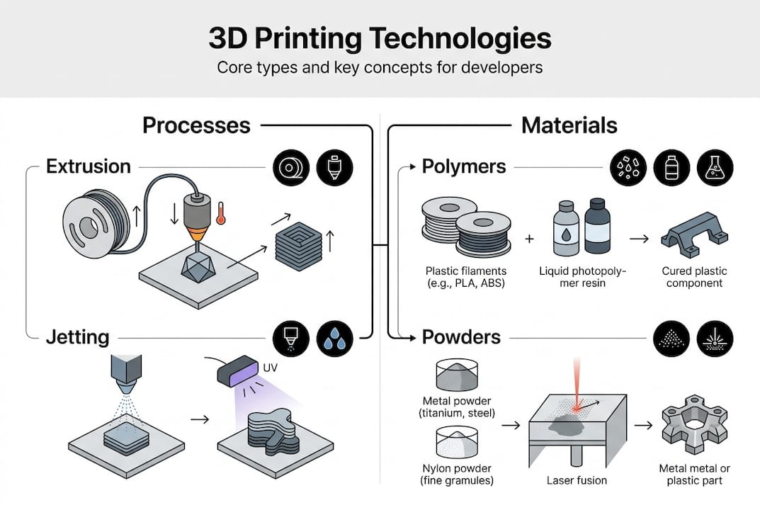
Core 3D printing technologies include Material Extrusion, Vat Photopolymerization, Powder Bed Fusion, Material Jetting, and Binder Jetting, each with unique strengths. Material Extrusion, commonly known as FDM or FFF, works by heating thermoplastic filament and depositing it layer by layer through a nozzle. This technology dominates prototyping and functional part production because of its accessibility and material variety, from standard PLA to engineering-grade nylon and carbon fiber composites.
Vat Photopolymerization includes SLA and DLP processes that cure liquid resin using UV light. These technologies excel at producing highly detailed parts with smooth surface finishes, making them ideal for intricate geometries and visual prototypes. Powder Bed Fusion encompasses SLS, DMLS, and MJF, which use lasers or heat to fuse powder particles. These processes create strong, functional parts without support structures, perfect for complex assemblies and end-use components.
Material Jetting resembles inkjet printing but deposits photopolymer droplets that cure immediately, enabling multi-material 3D printing with varying colors and properties in a single build. Binder Jetting sprays liquid binder onto powder layers, offering fast production speeds for large batches and metal parts that require sintering post-processing.
| Technology | Process Mechanism | Common Materials | Typical Applications |
|---|---|---|---|
| Material Extrusion (FDM/FFF) | Heated filament extrusion | PLA, ABS, Nylon, PETG, Composites | Prototypes, functional parts, tooling |
| Vat Photopolymerization (SLA/DLP) | UV light cures liquid resin | Standard, tough, flexible resins | High-detail models, dental, jewelry |
| Powder Bed Fusion (SLS/MJF) | Laser or heat fuses powder | PA12, PA11, TPU, metals | Functional parts, complex assemblies |
| Material Jetting (PolyJet) | Droplet deposition and UV cure | Photopolymers, multi-material | Visual prototypes, medical models |
| Binder Jetting | Binder sprayed on powder | Sand, metals, ceramics | Large batches, metal parts, casting |
Choosing the right technology requires matching your project requirements to process capabilities. Engineering-grade 3D printing demands understanding how each technology affects mechanical properties, surface finish, and dimensional accuracy.
Pro Tip: Match your material requirements and geometric complexity to technology first, then optimize for cost. A part with thin walls and fine details may cost less in SLA despite higher per-unit pricing because it eliminates extensive post-processing required with FDM supports.
The 3D printing technologies overview provides additional technical comparisons for advanced applications. When you need custom 3D printing solutions, understanding these fundamental differences helps you communicate requirements clearly and avoid costly revisions.
Common terminology for defects and quality factors in 3D printing
Quality issues in 3D printing stem from predictable causes that you can mitigate through proper terminology understanding and design choices. Recognizing defect patterns helps you troubleshoot failures and optimize your manufacturing process.
Warpage occurs when parts curl or bend during printing due to uneven cooling and internal stresses. This defect particularly affects large flat surfaces and corners in thermoplastic materials. Shrinkage describes dimensional changes as materials cool from processing temperature to room temperature, with different materials exhibiting varying shrinkage rates that affect final part accuracy. Delamination happens when layers separate due to poor adhesion, often caused by insufficient heat, contamination, or incorrect print parameters.
Distortion and warping from residual stresses and thermal gradients can be mitigated by orientation, supports, and heat treatment. Understanding these root causes empowers you to make informed design decisions before production begins. Residual stress builds up as each layer cools and contracts while bonded to previous layers, creating internal tension that manifests as warpage or cracking.
Thermal gradients describe temperature differences within a part during printing, with areas near the build plate staying warmer while upper layers cool rapidly. These gradients drive many quality issues in FDM printing. Print orientation refers to how you position a part on the build platform, directly affecting strength, surface quality, and support requirements. Strategic orientation minimizes thermal gradients and reduces warpage risk.
Support structures are temporary scaffolding that holds overhanging features during printing. These supports require removal during post-processing and can leave surface marks. Different support types include:
- Linear supports that create vertical columns beneath overhangs
- Tree supports that branch from a central trunk to minimize contact points
- Breakaway supports designed for easy manual removal
- Soluble supports that dissolve in chemical baths for complex geometries
Heat treatment post-processing includes annealing to relieve residual stresses and improve dimensional stability. This process involves heating printed parts in a controlled environment below the glass transition temperature, allowing molecular chains to relax and redistribute internal stresses. The result is improved dimensional accuracy and reduced warpage in finished parts.
Pro Tip: Test your specific material and printer combination to determine maximum unsupported overhang angles. Most FDM printers handle 45-degree overhangs without supports, but this varies by material flow characteristics and cooling efficiency. Document your results to optimize future designs.
When producing 3D printed prototypes and repair parts, understanding defect terminology helps you specify quality requirements and acceptance criteria. Reviewing 3D modeling and CAD projects shows how design choices prevent common quality issues before printing begins.
Mechanical properties and material-related terms essential for engineers
Mechanical property terminology bridges material science and practical engineering, helping you select appropriate materials and predict part performance under load. These terms define how printed parts behave in real-world applications.
Tensile strength measures the maximum stress a material withstands before breaking when pulled apart, expressed in megapascals (MPa). This property varies significantly based on print parameters and orientation. Yield strength indicates the stress level where permanent deformation begins, marking the transition from elastic to plastic behavior. Ductility describes how much a material can deform before fracturing, with higher ductility allowing greater elongation under stress.
Anisotropy coefficient quantifies how mechanical properties vary with direction in 3D printed parts. Unlike injection-molded parts with relatively uniform properties, printed parts exhibit different strengths parallel versus perpendicular to layer lines. This directional dependence stems from the layer-by-layer construction process, where interlayer bonding typically provides less strength than in-layer cohesion.
PLA tensile strength is optimized by layer thickness, angle, and speed, while PA-CF composites offer superior ductility and stiffness versus ASA or nylon. Process parameters dramatically impact final properties. Layer thickness affects bonding surface area between layers, with thinner layers generally providing better interlayer adhesion but longer print times. Print angle relative to load direction determines whether forces act along strong in-layer bonds or weaker interlayer interfaces.
PA12 SLS and MJF achieve tensile strength around 48 MPa, while PLA FDM varies from 40-60 MPa depending on parameters. These benchmarks help you evaluate material suitability for specific applications.
| Material/Process | Tensile Strength (MPa) | Key Characteristics | Best Applications |
|---|---|---|---|
| PLA FDM | 40-60 | Easy printing, biodegradable, brittle | Prototypes, visual models |
| PA12 SLS/MJF | 48 | Isotropic, durable, flexible | Functional parts, assemblies |
| PA-CF Composite | 70-90 | High stiffness, low weight | Structural components, tooling |
| ABS FDM | 35-45 | Impact resistant, heat tolerant | Functional prototypes, housings |
| Tough Resin SLA | 55-65 | High detail, moderate toughness | Snap-fit parts, jigs |
Factors affecting mechanical performance in 3D printing include:
- Layer height and width ratios that determine bonding surface area
- Print speed affecting material flow and layer fusion quality
- Nozzle temperature controlling melt viscosity and interlayer bonding
- Infill density and pattern distributing internal stress
- Raster angle determining load-bearing orientation relative to layers
Composite materials incorporate reinforcing fibers like carbon or glass into base polymers, significantly improving stiffness and strength. These materials require specialized nozzles and print parameters but deliver mechanical properties approaching traditional manufacturing methods. Understanding how fiber orientation aligns during extrusion helps you design parts that maximize reinforcement benefits.
When developing 3D printed prototypes and repair parts for functional testing, specifying mechanical property requirements ensures parts perform as intended. On-demand 3D printing services can help you iterate quickly through material options to find the optimal balance of properties for your application.
Support structures and orientation: terms that impact design and print success
Support strategy and part orientation represent critical decisions that affect print quality, material usage, and post-processing labor. Mastering this terminology helps you optimize designs for manufacturability.
Support structures serve as temporary scaffolding that prevents sagging or collapse during printing. Tree supports branch from a minimal base to contact points on the part, reducing material usage and contact marks compared to linear supports. These organic structures work particularly well for complex geometries with multiple overhangs. Chamfers are angled transitions that reduce sharp corners, often eliminating support requirements by keeping surfaces within printable overhang angles.
Orientation determines which surfaces face up, down, and sideways during printing. This choice affects multiple factors simultaneously: surface finish quality, mechanical strength direction, support requirements, and build time. Bottom surfaces typically show support marks and roughness, while top surfaces achieve better finish quality. Side surfaces display visible layer lines that affect aesthetics and dimensional accuracy.
The relationship between orientation and mechanical properties stems from anisotropy. Parts loaded parallel to layer lines leverage strong in-layer bonding, while loads perpendicular to layers stress weaker interlayer interfaces. Strategic orientation aligns the strongest material direction with primary load paths.
To optimize orientation and minimize supports, follow these steps:
- Identify critical surfaces requiring high quality finish and position them facing up or at angles avoiding supports.
- Analyze load directions and orient parts so primary stresses act parallel to layer lines for maximum strength.
- Evaluate overhang angles throughout the geometry and rotate to minimize surfaces exceeding your printer’s capability.
- Balance competing requirements by prioritizing functional over aesthetic surfaces when compromises are necessary.
- Test orientation options using slicer software preview to visualize support generation and estimate material usage.
- Document successful orientations for similar geometries to build institutional knowledge for future projects.
Pro Tip: Print test coupons at various orientations and overhang angles using your specific material and printer settings. Mechanical testing reveals actual strength differences, while visual inspection shows surface quality variations. This empirical data guides design decisions more accurately than generic material specifications.
Design adjustments based on orientation knowledge include adding chamfers to eliminate supports, splitting parts along optimal planes for separate printing and assembly, and incorporating self-supporting angles into organic shapes. These modifications reduce post-processing while improving final part quality.
Leveraging professional 3D printing services provides access to expertise in orientation strategy and support optimization. Experienced technicians understand how different geometries behave across various materials and can recommend design modifications before printing. 3D modeling and CAD services help you implement design for additive manufacturing principles that account for orientation and support considerations from the start.
Explore expert 3D printing services and solutions
Applying the terminology and concepts covered in this guide becomes significantly easier when you work with experienced 3D printing professionals who understand these technical nuances. CC 3D Labs specializes in translating engineering requirements into optimized print strategies that deliver functional, accurate parts.

Our 3D printing services encompass everything from rapid prototyping to production runs, with expertise across multiple technologies and materials. When your project demands engineering-grade 3D printing with specific mechanical properties or tight tolerances, our team applies the terminology and best practices discussed here to ensure successful outcomes. We also offer comprehensive 3D modeling and CAD services to optimize your designs for additive manufacturing, addressing orientation, supports, and material selection before production begins. Whether you need a single prototype or batch production, our Philadelphia-based facility delivers precision parts with quick turnaround times.
Frequently asked questions
What is the difference between FDM and SLA 3D printing?
FDM extrudes melted thermoplastic filament through a heated nozzle, building parts layer by layer through material deposition. SLA uses a UV laser or projector to selectively cure liquid photopolymer resin in a vat. FDM generally costs less per part and offers wider material options including engineering thermoplastics, while SLA delivers higher resolution and smoother surface finishes ideal for detailed prototypes.
How does print orientation affect 3D printed parts?
Orientation determines which direction layers stack relative to part geometry, directly influencing mechanical strength, surface quality, and support requirements. Parts are strongest when loaded parallel to layer lines due to continuous material paths within each layer. Orienting critical surfaces upward or at self-supporting angles minimizes support contact marks and improves finish quality.
What is anisotropy in 3D printing and why does it matter?
Anisotropy means mechanical properties vary depending on the direction of measurement relative to print layers. This occurs because interlayer bonding typically provides less strength than in-layer material cohesion. Engineers must account for anisotropy when designing functional parts by aligning the strongest material direction with primary load paths to prevent premature failure.
When are support structures necessary in 3D printing?
Supports are required for overhanging features that exceed your printer’s maximum unsupported angle, typically around 45 degrees for FDM. Complex geometries with undercuts, bridges, or hollow sections also need supports to prevent sagging or collapse during printing. Choosing appropriate support types like tree supports versus linear supports reduces material waste and simplifies removal while maintaining part quality.
How do process parameters affect tensile strength in FDM printing?
Layer thickness, print speed, and nozzle temperature directly impact how well layers bond together, affecting overall part strength. Thinner layers increase bonding surface area between layers, improving interlayer adhesion. Higher nozzle temperatures reduce melt viscosity, promoting better layer fusion, while optimal print speeds allow sufficient time for thermal bonding without compromising dimensional accuracy through excessive material flow.