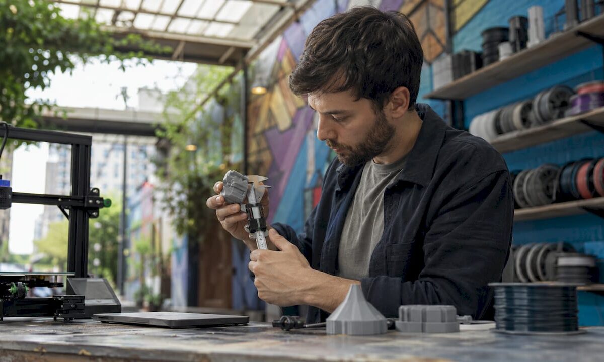
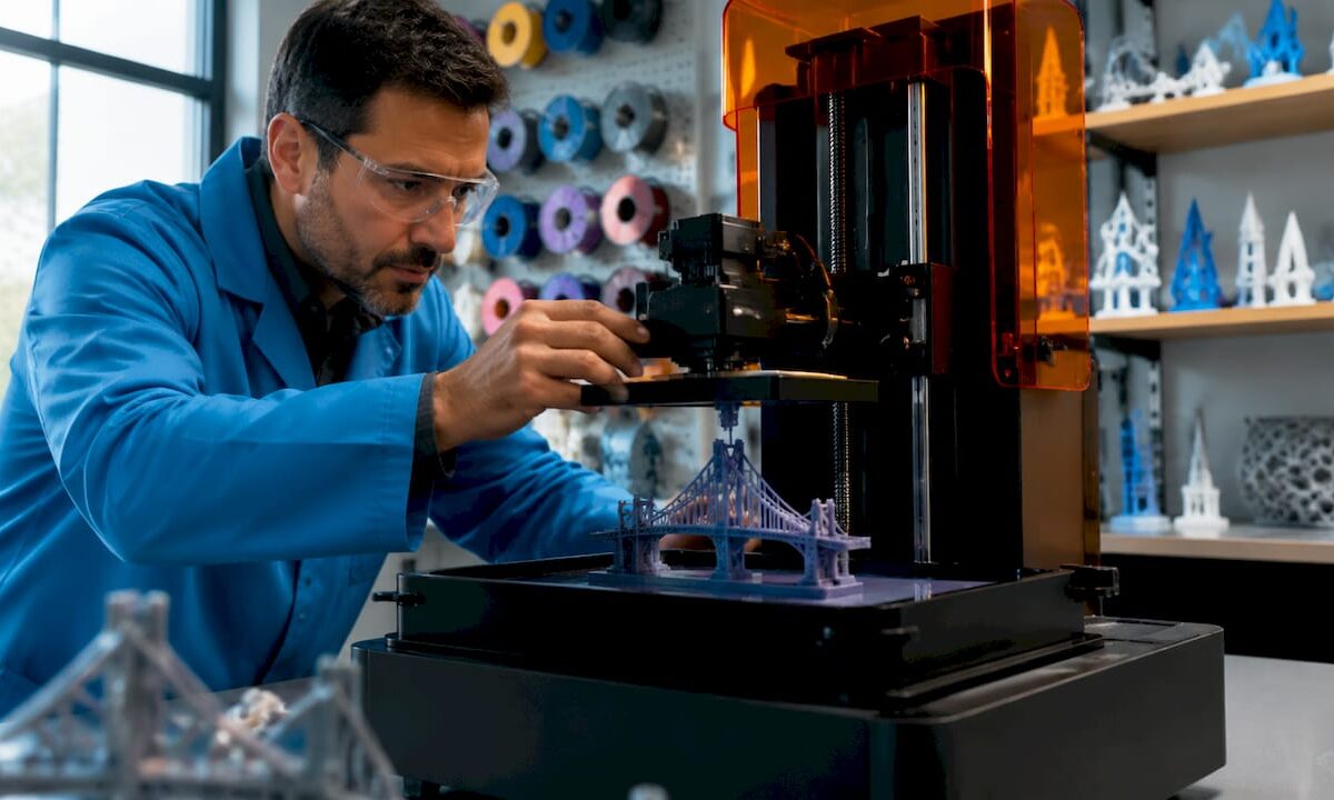
Engineer adjusting 3D printed prototype at bench

Print Orientation in 3D Printing: A Practical Guide


TL;DR:

  • Print orientation in 3D printing determines a model’s position on the build plate, affecting strength, finish, support needs, and print time. Properly aligning layers with the primary load direction enhances part durability, while surface quality depends on how flat surfaces are oriented relative to the build plate. Using the correct orientation minimizes supports and reduces overall production costs and duration.

Print orientation is defined as the position and direction a 3D model occupies on the build plate before and during printing. That single decision shapes the part’s mechanical strength, surface finish, support material needs, and total print time. Hobbyists and product developers alike often treat orientation as an afterthought. Professionals at shops like Cc3dlabs treat it as the first design decision. This guide breaks down every major effect of print orientation so you can make smarter choices before your next print starts.

What is print orientation and why does it matter in 3D printing?

Print orientation, known in manufacturing as build orientation, is the angle and axis at which a model is placed relative to the build plate in a 3D printer. In FDM (Fused Deposition Modeling) printing, the printer deposits material layer by layer from the bottom up. The direction those layers stack determines almost everything about the final part.

Think of it like wood grain. A plank of wood is strong along the grain and splits easily across it. FDM printed parts behave the same way. FDM parts are anisotropic, meaning their strength varies depending on the direction of the applied force relative to the layer lines. That single fact is the foundation of every orientation decision you will make.

Orientation also controls how tall a print is, which directly affects how many layers the printer must deposit. More layers mean more time. The wrong orientation can also force the slicer to generate support structures for overhangs, adding material waste and post-processing work. Getting orientation right before you hit print is the highest-leverage decision in the entire workflow.

How does print orientation affect the strength of a 3D printed part?

The bond between two adjacent layers in an FDM print is always weaker than the continuous filament running within a single layer. Stress applied perpendicular to layer interfaces causes delamination and reduced tensile strength. That is the core mechanical risk of poor orientation.

The fix is straightforward: align the primary load direction with the layer lines, not across them. If a bracket will be pulled along its length, print it so the layers run lengthwise. If a clip will flex open and closed, orient it so the bending stress runs parallel to the layers, not perpendicular to them. This is how you validate 3D designs for real-world loads before committing to a production run.
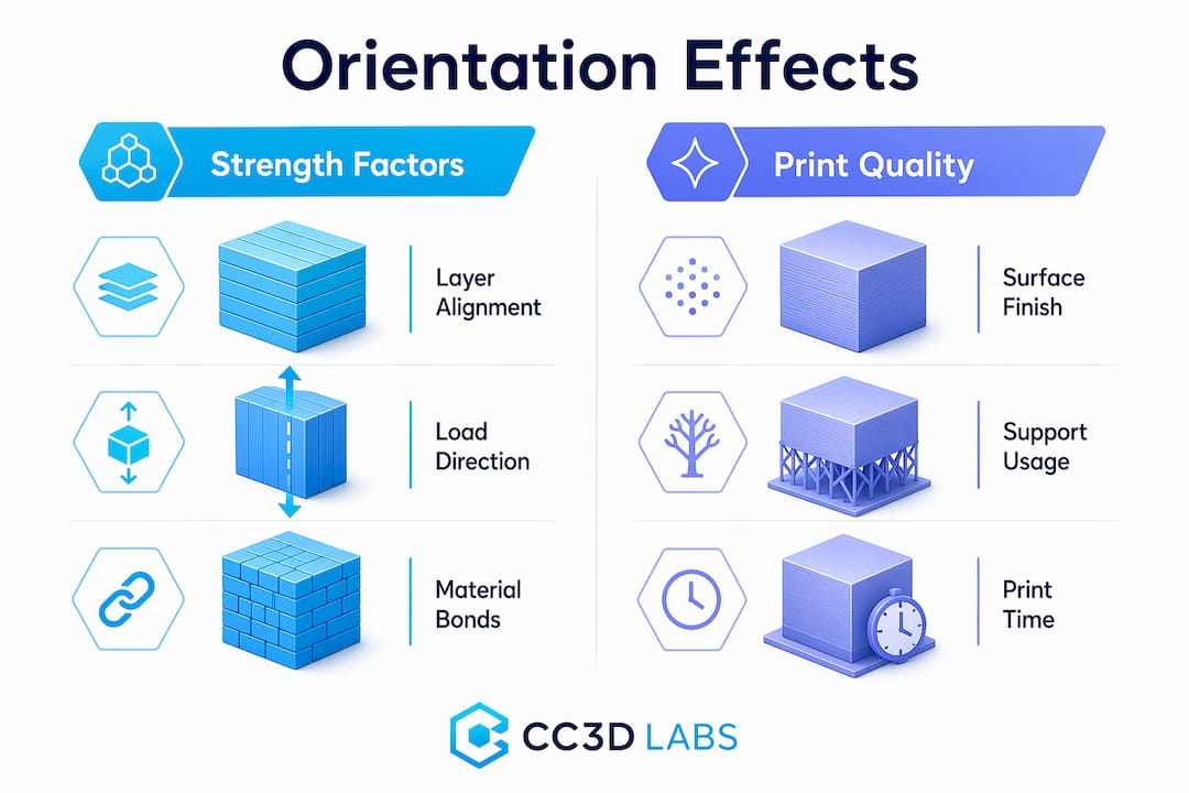
Infographic comparing strength and print quality effects by orientation

SLA and SLS technologies are less sensitive to this issue. SLA parts cure in a resin pool and have more isotropic properties. SLS parts are sintered in powder and show minimal directional weakness. But for FDM, which covers the vast majority of desktop and professional filament printers, orientation is a structural decision, not just a visual one.

Pro Tip: Orient load-bearing surfaces parallel to the build plate. That keeps the strongest filament continuity aligned with the direction of stress and dramatically reduces the risk of layer separation under load.

What impact does print orientation have on surface finish and aesthetics?

Surface finish is where orientation choices become visible to anyone who picks up the part. Flat surfaces printed parallel to the build plate produce the smoothest result because the layers stack cleanly on top of each other with minimal visible stepping.

Angled or vertical faces tell a different story. When a curved or diagonal surface rises along the Z-axis, each layer creates a small horizontal step. This is called the stair-stepping effect, and it becomes more pronounced as the surface angle becomes shallower relative to the build plate. A 15-degree slope will show far more stepping than a 60-degree slope.

Here are the key rules for orientation when appearance matters:

  • Cosmetic faces go down or sideways. Place the most visible surface against the build plate or parallel to it for the smoothest result.
  • Avoid the Z-axis for precision fits. Critical mating surfaces oriented along the Z-axis lose dimensional accuracy due to stair-stepping, which can ruin a snap-fit or press-fit joint.
  • Curved features need careful planning. Cylinders printed vertically show stepping around their circumference. Printing them horizontally produces a smoother outer wall but weakens the part along its length.
  • Prioritize the surface the end user will see. If only one face of a part is visible in its final assembly, orient that face for the best finish, even if it means a slightly weaker structure elsewhere.

The trade-off between strength and surface finish is the most common tension in orientation decisions. There is rarely a single orientation that maximizes both. The key is knowing which property matters more for your specific part.

How does print orientation influence support material usage and print efficiency?

Supports are structures the slicer generates automatically to hold up any portion of the model that overhangs more than roughly 45 degrees from vertical. Overhangs greater than 45 degrees require support material, which increases filament consumption and adds post-processing time for removal and sanding. Optimizing orientation to minimize supports can reduce filament consumption by 20–50%. That is a significant cost and time saving on any print, and it compounds across batch production runs.

Print time is the second efficiency factor. Taller parts require more layers, and each additional layer adds time. A part printed upright at 120mm tall will take considerably longer than the same part printed flat at 30mm tall. Reducing vertical height by rotating the model is one of the fastest ways to cut print duration without changing any slicer settings.

The table below shows how the three main orientation strategies compare across the key efficiency metrics:

Orientation Support volume Print time Surface quality Strength direction
Flat (horizontal) Low Fast High on top face Strong along XY plane
Upright (vertical) Medium Slow Moderate on sides Strong along Z-axis
Angled (tilted) High Medium Variable Distributed across axes

Pro Tip: Decide on orientation during the design phase, not after the model is finished. Small geometry changes, like adding a flat face or chamfering an overhang, can eliminate entire support structures and save hours of print time and post-processing.

You can find more detail on reducing waste and labor through smart orientation in this guide to cutting 3D printing costs.

What are the main print orientation types in 3D printing?

The three primary orientation types in 3D printing are flat, upright, and angled. Each produces a different balance of strength, finish, and efficiency.
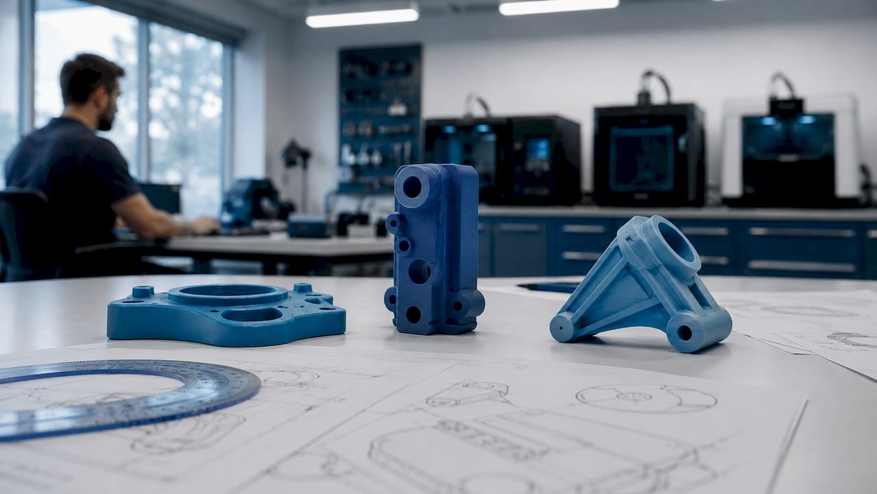
3D prints showing flat, upright, and angled orientations

Flat orientation places the model with its largest face on the build plate. This minimizes print height, reduces supports, and produces the best surface finish on the top face. It is the default choice for wide, thin parts like brackets, panels, and trays.

Upright orientation stands the model on its smallest face, maximizing height along the Z-axis. This is useful when you need strength along the part’s length or when the bottom face has critical geometry that must be preserved. The trade-off is longer print times and more visible layer lines on the sides.

Angled orientation tilts the model at a custom angle, often 30–45 degrees. This distributes layer lines across multiple surfaces, which can improve strength in multiple directions simultaneously. It often increases support volume, so it works best when the geometry has no clean flat face to rest on.

For context, the concept of orientation also appears in standard 2D document printing. Portrait orientation is taller than wide; landscape is wider than tall. Portrait suits vertical reading flow, while landscape favors horizontal data layouts like spreadsheets and charts. The analogy is useful: just as you choose a page orientation based on content layout, you choose a 3D build orientation based on part function.

2D orientation Aspect ratio Best use
Portrait Taller than wide Documents, letters, vertical images
Landscape Wider than tall Spreadsheets, presentations, wide graphics

In 3D printing, the logic scales up. The “layout” is the part’s geometry, and the “content” is its mechanical and aesthetic requirements.

How to set and choose the best print orientation for your project

Selecting the right orientation is a structured process, not a guess. Follow these steps to make a defensible decision every time.

  1. Identify the primary load direction. Ask where the part will experience the most stress. Align the layers to run parallel to that force, not across it.
  2. Identify the cosmetic surfaces. Determine which faces will be visible or need a smooth finish. Plan to orient those faces parallel to the build plate or away from the Z-axis.
  3. Assess overhang geometry. Rotate the model in your slicer, such as Ultimaker Cura, PrusaSlicer, or Bambu Studio, and look for overhangs greater than 45 degrees. Adjust orientation to eliminate as many as possible before adding supports.
  4. Check vertical height. Compare print time estimates at different orientations. A shorter Z-height almost always means a faster print. Use your slicer’s layer preview to confirm.
  5. Run a test print. For functional parts, print a small section or a simplified version at your chosen orientation before committing to the full part. This is standard practice in 3D part optimization workflows.
  6. Iterate based on results. No perfect orientation exists. Professionals treat orientation as an iterative decision that gets refined with each print. Document what worked and why.

Pro Tip: Prioritize end-use requirements before locking in orientation. A decorative part should be oriented for finish. A structural part should be oriented for strength. Trying to optimize both at once usually produces a part that excels at neither.

For more guidance on designing parts that print reliably from the start, see this resource on designing reliable prototypes.

Key takeaways

Print orientation is the single most impactful pre-print decision in FDM 3D printing, controlling strength, surface finish, support volume, and total print time simultaneously.

Point Details
Orientation controls strength Align layer lines with the primary load direction to prevent delamination and maximize tensile strength.
Surface finish depends on axis Flat surfaces parallel to the build plate are smoothest; Z-axis faces show the most stair-stepping.
Supports add cost and time Minimizing overhangs through smart orientation can cut filament use by 20–50% per print.
Taller prints take longer Reducing vertical height by rotating the model is the fastest way to shorten print duration.
Iteration is standard practice No single orientation is perfect; test, document, and refine based on actual part performance.

The trade-off no one talks about honestly

I have reviewed hundreds of parts that came in for printing with the orientation already locked in by the designer. The most common mistake is not choosing the wrong axis. It is assuming that one orientation can satisfy every requirement at once.

A hobbyist will orient a functional bracket for the best-looking surface finish, then wonder why it snapped under load. A product developer will orient a prototype for maximum strength, then spend an hour sanding off support scars from the mating face. Both are making the same error: treating orientation as a single-variable problem when it is always a multi-variable trade-off.

What I tell every client is this: write down the two most important properties for your part before you open the slicer. If strength ranks first, orient for strength and accept the surface finish you get. If appearance ranks first, orient for finish and reinforce the design with geometry, like ribs or gussets, to compensate for reduced layer strength. Trying to split the difference without a clear priority usually produces a mediocre result on both fronts.

The other thing worth saying plainly: slicers like PrusaSlicer and Bambu Studio have auto-orientation features. They are useful starting points, not final answers. They optimize for support reduction, not for your specific load case. Always override the auto-suggestion with your own analysis of how the part will actually be used.

— Justin

Get orientation right the first time with Cc3dlabs

https://cc3dlabs.com

Cc3dlabs, based near Philadelphia, applies professional orientation analysis to every custom filament print it produces. Whether you are printing a single prototype or a batch of functional parts, the team evaluates load direction, surface requirements, and support geometry before a single layer is deposited. That process is what separates a part that performs from one that just looks like it will.

If you want expert eyes on your next project, explore Cc3dlabs’ professional 3D printing services or browse the full range of on-demand printing options for prototypes and custom parts. Free online estimates are available, and the team supports both local pickup near Philadelphia and international shipping.

FAQ

What is print orientation in 3D printing?

Print orientation is the position and angle at which a 3D model is placed on the build plate before printing. It directly controls the part’s strength, surface finish, support requirements, and print time.

Which orientation produces the strongest FDM printed part?

The strongest orientation aligns the primary load direction parallel to the layer lines. Stress applied perpendicular to layer interfaces causes delamination, so the load vector should run along the filament layers, not across them.

How does orientation affect support material usage?

Overhangs greater than 45 degrees require support structures. Rotating a model to reduce steep overhangs can cut filament consumption by 20–50% and significantly reduce post-processing time.

What is the difference between portrait and landscape orientation?

In 2D printing, portrait orientation is taller than wide and suits vertical documents, while landscape is wider than tall and works best for horizontal layouts like spreadsheets and presentations. In 3D printing, the equivalent choices are flat, upright, and angled orientations based on part geometry and function.

Can slicing software choose the best orientation automatically?

Slicers like PrusaSlicer and Bambu Studio include auto-orientation tools that minimize supports, but they do not account for your specific load case or cosmetic priorities. Use auto-orientation as a starting point, then adjust based on how the part will actually be used.
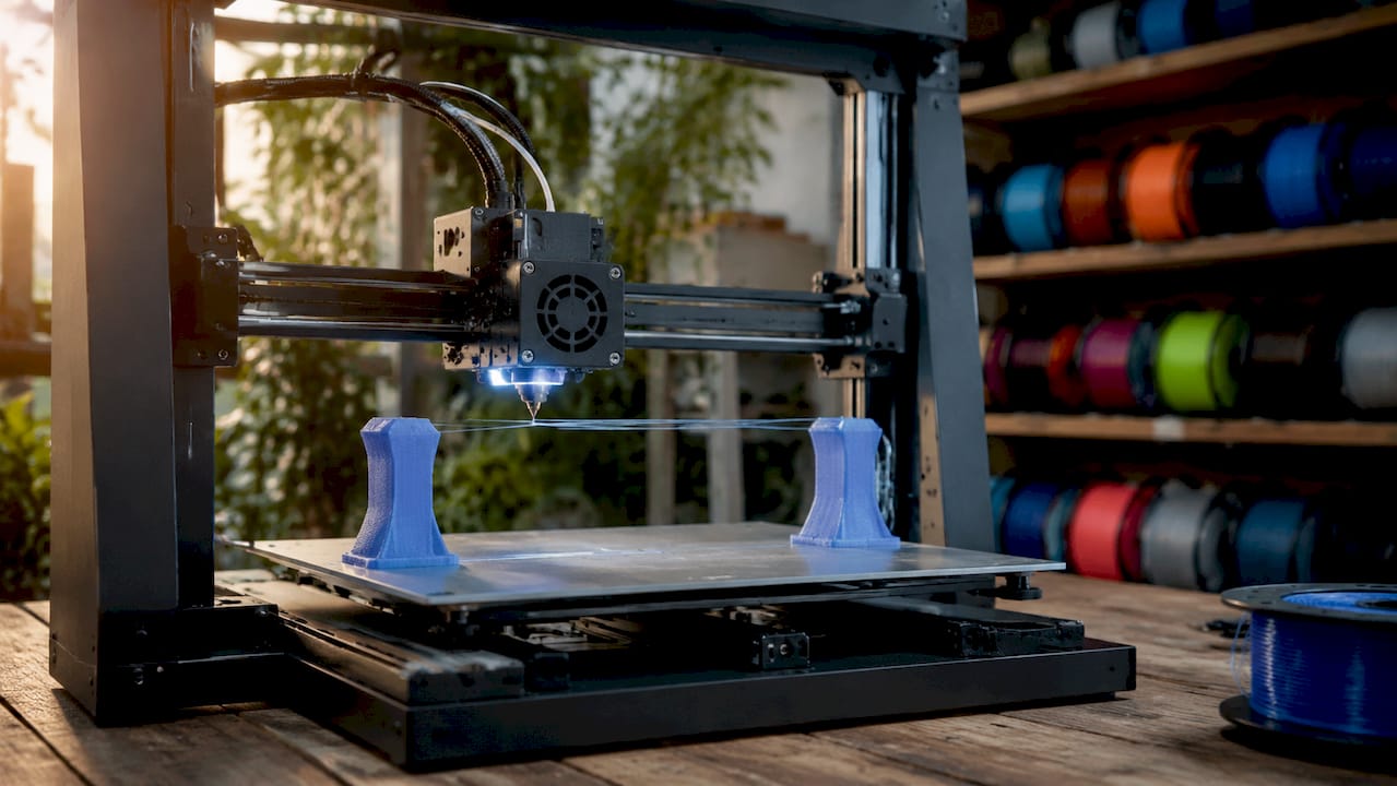
Technician adjusting 3D printer bridging filament

Bridging in 3D Printing: A Practical Guide


TL;DR:

  • Bridging in 3D printing involves extruding filament horizontally between two anchored points without support structures. Proper cooling, speed, and geometry design are essential to produce strong, sag-free spans, with PLA being the ideal filament for bridging due to its fast cooling. Adjusting slicer settings and redesigning parts can reduce reliance on supports and improve print quality across various filament types.

Bridging in 3D printing is defined as the process of extruding filament horizontally between two anchored points without any material beneath to support it. This technique is central to explaining bridging in 3D printing because it determines whether a design needs support structures or can print cleanly on its own. The industry term is “FDM bridging,” and it applies to any filament-based printer using fused deposition modeling. Most well-tuned FDM printers bridge 50–80mm without supports, while optimized setups exceed 100mm. That range tells you exactly how much geometry you can get away with before supports become unavoidable.

How does bridging work in 3d printing?

Bridging works by pulling extruded filament taut between two fixed anchor points, much like stringing a wire between two posts. The extruder moves across the gap while depositing molten filament, and the key is that the filament must solidify before gravity pulls it down. Without rapid cooling, the strand sags and ruins the surface below.

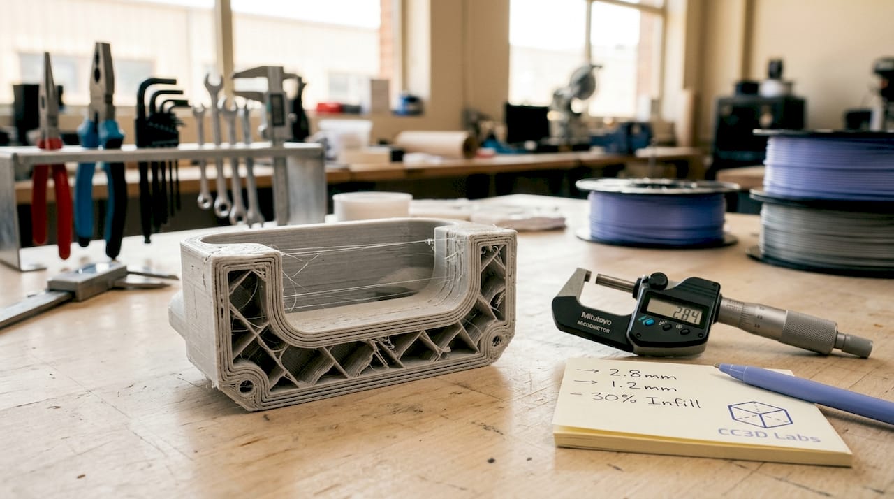
Close-up of 3D printer creating filament bridge

Bridging differs from overhangs in one critical way: the filament is anchored at both ends, not just one. An overhang extends outward from a single wall with nothing on the far side. A bridge connects two walls, which gives the extruded strand tension on both ends. That tension is what makes bridging physically possible without support.

The cooling system does the heavy lifting. As the nozzle moves across the gap, the part cooling fan blasts the freshly extruded filament to freeze it in place before it can droop. Speed matters here too. Move too fast and the filament snaps or under-extrudes. Move too slow and the filament stays molten too long and sags under its own weight.

Pro Tip: Run a dedicated bridge calibration test before printing your actual part. Files like the “Bridging Test” models on Printables let you dial in speed and cooling on a throwaway print rather than discovering problems mid-job on a complex prototype.

What slicer settings produce the best bridges?

Slicer settings control the outcome of every bridge you print. Getting them right means understanding how cooling, speed, and flow rate interact with each other.

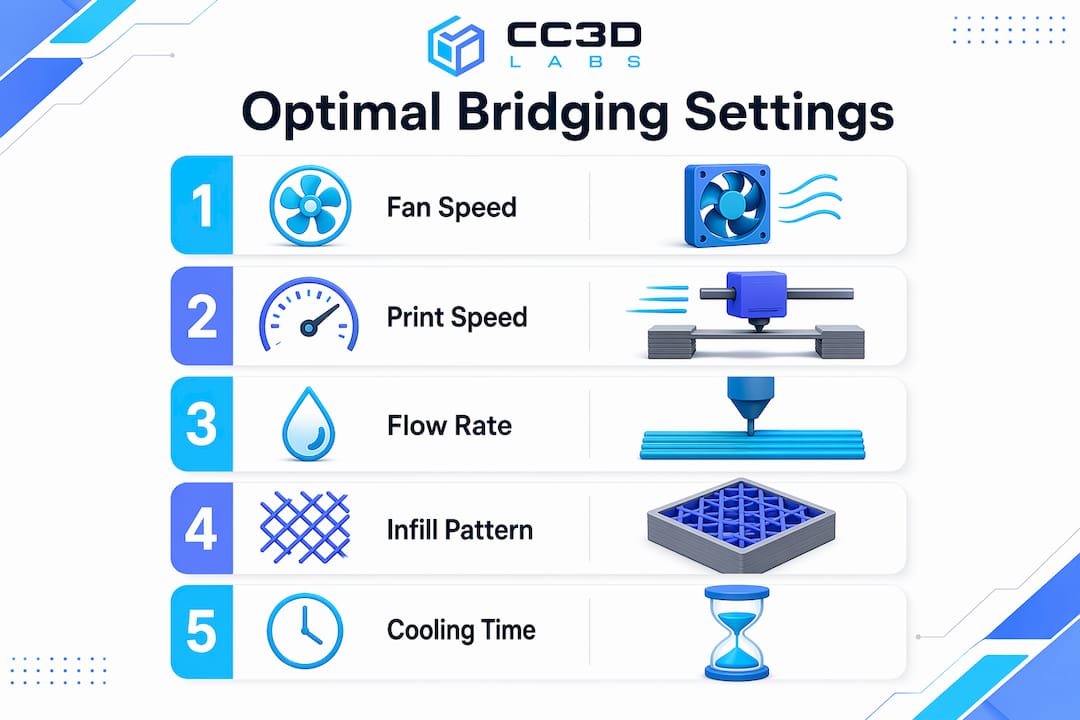
Infographic of key slicer settings for bridging

Cooling

Optimal bridging requires 100% fan speed for most materials. The faster the filament solidifies, the less it sags. ABS and ASA are the major exceptions. Those materials require 30% fan speed or less to prevent thermal warping and layer delamination. Pushing full cooling on ABS will crack the part before the bridge even finishes.

Print Speed

Bridging speed typically falls between 20–80 mm/s depending on the printer and filament. Slower speeds give the cooling fan more time to solidify each strand, which improves surface quality. Faster speeds reduce the time filament stays molten mid-air, which can help with tension. Most users find 30–40 mm/s is the sweet spot for PLA on a well-tuned machine.

Flow Rate and Infill Pattern

Reducing bridge flow to 80–95% prevents excess molten material from building up mid-span. Less material means less weight pulling the strand down. Concentric bridge infill patterns also outperform linear ones because they distribute tension more evenly across the span. Slicers like Simplify3D, PrusaSlicer, and Cura all offer dedicated bridge settings menus where you can override these values independently from the rest of the print.

Pro Tip: Some advanced users push external bridge flow rates up to 140–150% combined with slower speeds. Higher flow rates at lower speeds can improve strand bonding by expanding filament laterally, creating a more uniform surface. Test this on scrap prints first.

What are the most common bridging problems?

Bridge failures follow predictable patterns. Knowing the cause cuts your troubleshooting time in half.

  1. Sagging strands. The most common failure. Caused by insufficient cooling, excessive print temperature, or a span that exceeds the printer’s capability. Drop your print temperature by 5°C and increase fan speed before changing anything else.

  2. Stringing across the gap. Happens when retraction settings are not tuned for bridging. The nozzle oozes material as it travels, leaving thin threads across the span. Increase retraction distance slightly and reduce travel speed.

  3. Drooping at the center. A longer span issue. The filament holds at the anchors but sags in the middle. Shorten the span through part redesign, or split the bridge into two shorter sections with a mid-span support column.

  4. Inconsistent extrusion. The bridge looks uneven or has gaps. Hardware issues like clogged nozzles or wet filament produce extrusion inconsistencies that mimic slicer setting errors. Dry your filament and clean the nozzle before adjusting any parameters.

  5. Warping at bridge edges. Common with ABS and ASA. The rapid temperature change at the bridge edges causes the corners to lift. Reduce cooling, increase bed temperature, and consider an enclosure.

Pro Tip: Bridge failures often signal cooling or geometry issues rather than a simple settings error. Always check hardware first. A partially clogged nozzle will make every bridge look like a settings problem when the real fix is a cold pull.

How does filament type affect bridging?

Every filament behaves differently mid-air. Matching your settings to your material is non-negotiable for consistent results.

  • PLA is the best material for bridging. It cools fast, holds tension well, and tolerates 100% fan speed without warping. Most bridging benchmarks and tutorials use PLA as the baseline. If you are learning to tune bridges, start here.

  • ABS and ASA require a fundamentally different approach. Full cooling causes warping and layer separation. Keep fan speed at 30% or below, slow the bridge speed to 20–25 mm/s, and use an enclosure to maintain ambient temperature. Bridging spans with ABS should be kept shorter than with PLA. For a deeper look at how these materials compare, the PLA vs. PETG vs. ABS guide from Cc3dlabs covers mechanical trade-offs in detail.

  • PETG sits between PLA and ABS in bridging difficulty. It strings aggressively and stays tacky longer than PLA, which causes strands to sag and stick to each other. Reduce flow to 80%, increase retraction, and run fan speed at 50–70%. Expect more post-processing cleanup on PETG bridges.

  • Flexible filaments like TPU are nearly impossible to bridge cleanly. The material stretches under tension instead of holding taut. For flexible parts with horizontal spans, support structures are the only reliable option.

The pattern across all materials is the same: faster cooling and lower flow rates improve bridge quality, but each material has a ceiling on how much cooling it can tolerate before other problems appear.

Design strategies that reduce bridging problems

Smart geometry eliminates many bridging problems before the print even starts. The table below compares common design approaches and their trade-offs.

Strategy Best For Trade-Off
Add chamfers at 45° Replacing flat bridges with angled surfaces Slightly changes part geometry
Split bridge into segments Long spans over 60mm Requires mid-span support columns
Reorient the part Shortening bridge direction May increase total print height
Reduce span width in CAD All bridging scenarios Requires design iteration
Use a teardrop hole shape Circular holes on vertical faces Changes hole aesthetics

Part redesign to reduce bridge span is the preferred approach in batch production because it eliminates post-processing labor and reduces failure rates at scale. Adding a 45° chamfer to the underside of a horizontal feature converts a flat bridge into a series of short overhangs, which most printers handle without any special settings. For production-focused design decisions, the 3D part optimization guide from Cc3dlabs walks through geometry choices that reduce support dependency across entire part families.

Reorienting the part on the build plate is often the fastest fix. A span that runs 80mm in one orientation might only run 30mm when the part is rotated 90°. That single change can move a print from “needs supports” to “prints clean” with zero CAD edits. For low-volume production runs, the low-volume manufacturing guide covers when orientation changes deliver the most value.

Key takeaways

Successful bridging in FDM printing depends on matching cooling, speed, and flow rate to your specific material, then designing geometry that keeps spans within your printer’s capability.

Point Details
Standard bridging span Most FDM printers handle 50–80mm cleanly; optimized setups exceed 100mm.
Cooling is the primary lever Run 100% fan speed for PLA; limit ABS and ASA to 30% or less to prevent warping.
Flow rate matters Set bridge flow to 80–95% to reduce mid-span sag and excess material buildup.
Check hardware before settings Clogged nozzles and wet filament mimic slicer errors; fix hardware first.
Design beats troubleshooting Chamfers, part reorientation, and shorter spans outperform support structures in production.

What i’ve learned after years of watching bridges fail

The most common mistake I see is treating bridging as a pure settings problem. Someone gets a saggy bridge, opens their slicer, and starts adjusting fan speed and flow rate for an hour. Then they discover the filament spool has been sitting open for three weeks and absorbed moisture. Wet filament produces inconsistent extrusion that no slicer setting can fix. Dry your filament first. Clean your nozzle. Then tune settings.

The second thing I’ve changed my mind on is supports. Early in my experience, I added supports liberally because they felt like a safety net. Now I treat them as a last resort. Every support structure adds post-processing time, leaves surface marks, and increases material cost. A well-placed chamfer or a 10-minute CAD edit almost always beats an hour of support removal and surface cleanup. For anyone running batch production, that math compounds fast.

The emerging trend worth watching is higher bridge flow rates. Pushing flow to 140–150% combined with slower speeds is counterintuitive, but the logic holds. Wider strands bond to each other more effectively, creating a more solid surface. I’ve tested this on PLA with good results, though it requires careful calibration to avoid over-extrusion at the anchor points. It is not a setting to deploy without testing, but it is worth experimenting with on complex geometries.

My overall advice: be methodical. Change one variable at a time, run a calibration print, and document what you observe. Bridging is solvable for almost any geometry if you approach it systematically rather than randomly adjusting sliders.

— Justin

Get professional help with complex print geometry

When bridging challenges are holding back your prototype or production timeline, Cc3dlabs has the equipment and expertise to handle it.

https://cc3dlabs.com

Cc3dlabs, based near Philadelphia, specializes in custom filament-based 3D printing for prototypes, functional parts, and batch orders. The team tunes print parameters for each job, including bridge-specific settings, cooling profiles, and part orientation, so you get clean results without the trial-and-error cycle. Whether you need a single prototype or a production run with complex geometry, Cc3dlabs offers free online estimates, design support, and fast turnaround. Reach out to discuss your project and get a print that performs.

FAQ

What is bridging in 3d printing?

Bridging is the process of extruding filament horizontally between two anchored points without support material beneath. It is a standard FDM technique used to print horizontal spans cleanly without adding support structures.

How long of a bridge can a 3d printer handle?

Most well-tuned FDM printers handle spans of 50–80mm without supports. Optimized machines with dialed-in cooling and speed settings can exceed 100mm.

What is the best filament for bridging?

PLA is the best filament for bridging because it cools fast, holds tension well, and tolerates 100% fan speed. ABS, ASA, and PETG require lower cooling and more careful tuning.

Why does my bridge keep sagging?

Sagging is most often caused by insufficient cooling, excessive print temperature, or a span that exceeds your printer’s capability. Check for wet filament or a clogged nozzle before adjusting slicer settings.

Should i use supports instead of bridging?

Supports should be reserved for genuine geometry challenges after you have optimized cooling, speed, and part orientation. Redesigning the part with chamfers or shorter spans almost always produces better results than adding supports.

3D printer extruding fine layers of plastic part

Wall Thickness in 3D Printing: A Complete Guide


TL;DR:

  • Wall thickness in 3D printing refers to the solid outer perimeter layers that define a part’s boundary, separate from internal infill. Properly setting wall thickness ensures parts are strong, accurate, and durable, avoiding failures like cracking or warping. It is best designed as a multiple of the nozzle diameter, tailored to the specific material and technology used for optimal print reliability.

Wall thickness in 3D printing is defined as the measurement of the outer solid perimeter layers that form a part’s boundary, separate from the internal infill structure. This single parameter shapes whether a printed part survives real-world use or fails on first contact with stress. Get it wrong and you waste material, time, and filament on a part that cracks, warps, or prints with gaps. Get it right and you unlock prints that are strong, accurate, and built for their intended purpose. This guide covers what wall thickness means, how it interacts with your slicer and material, and how to dial it in for any print.

What is wall thickness in 3D printing?

Wall thickness is the outer shell thickness of a 3D printed part, forming the solid boundary between the part’s surface and its interior infill. It is not the same as infill density, and confusing the two is one of the most common mistakes in print design. Infill fills the interior volume at a chosen density pattern. Wall thickness defines the solid outer frame that holds everything together.

Cross section of 3D printed part walls

Some sources draw a further distinction between wall thickness and shell thickness. Wall thickness refers specifically to the vertical perimeters running along the sides of a part. Shell thickness includes those vertical walls plus the top and bottom solid layers. Understanding this difference matters when you are configuring a slicer, because the two settings are adjusted independently and affect different aspects of part performance.

Wall thickness also connects directly to nozzle diameter and layer height. A printer running a 0.4 mm nozzle extrudes lines of roughly that width, so every wall is built from stacked extrusion lines. This relationship between hardware and geometry is why wall thickness is not just a design choice but a printing parameter with physical constraints.

How wall thickness varies by technology and material

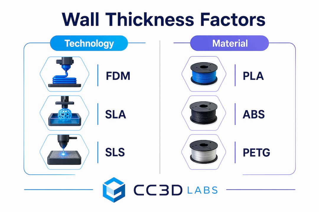
Minimum wall thickness values differ significantly across printing technologies because each process uses different physics to build parts. FDM (Fused Deposition Modeling) typically requires a minimum of 0.8 to 1.2 mm. SLA resin printing can go as thin as 0.5 mm. SLS Nylon powder bed printing sits around 0.7 to 1 mm. Metal DMLS processes require 1 to 2 mm due to thermal stress and sintering behavior.

These differences exist because powder bed and resin technologies support the part during printing, allowing thinner walls without collapse. FDM parts are built layer by layer in open air, requiring more material to maintain structural integrity during the print itself. This means a wall thickness that works perfectly in SLA will fail to print reliably in FDM on the same geometry.

Infographic comparing wall thickness by technology and material

Material choice adds another layer of complexity. PLA is stiff and prints well at thinner walls. ABS and PETG require slightly thicker walls to compensate for their tendency to warp or delaminate under stress. TPU, being flexible, needs thicker walls to maintain shape and resist tearing. Metal and engineering-grade materials demand the most conservative minimums because the consequences of failure are more severe.

The table below summarizes typical minimum wall thickness values by technology:

Technology Material Minimum wall thickness
FDM PLA, ABS, PETG 0.8 to 1.2 mm
SLA Standard resin 0.5 mm
SLS Nylon 0.7 to 1.0 mm
DMLS Metal alloys 1.0 to 2.0 mm
FDM TPU (flexible) 1.5 to 2.0 mm

Load-bearing parts and components that will be post-processed (sanded, painted, or drilled) should always target the upper end of these ranges. Visual models or display pieces can use minimums. The intended function of the part, not just the material, determines where in the range you should land.

Wall thickness vs. wall count vs. shell thickness in slicers

Slicer software like Orca Slicer, PrusaSlicer, and Bambu Studio each use slightly different terminology, but the underlying concepts are consistent. Understanding how these three terms relate to each other prevents costly misconfigurations.

Here is how the terms break down:

  1. Wall thickness is the total width of the outer perimeter. It equals the number of wall lines multiplied by the extrusion width.
  2. Wall count (also called perimeter count or wall line count) is the number of extrusion lines that form the outer shell. A 0.5 mm nozzle printing a 1.5 mm wall uses 3 wall lines.
  3. Shell thickness is the broader term that includes both the vertical walls and the top and bottom solid layers. Adjusting shell thickness in a slicer changes how many solid layers cap the top and bottom of the part.

For a 0.4 mm nozzle, a wall count of 2 produces a wall thickness of approximately 0.8 mm. A wall count of 3 produces 1.2 mm. This is why designing walls as multiples of the nozzle diameter avoids gaps and weak points in the perimeter. A wall designed at 1.0 mm with a 0.4 mm nozzle forces the slicer to either squeeze in 2.5 lines (impossible) or adjust the extrusion width, which can introduce inconsistencies.

Slicers also enforce minimum printable widths. When a wall in your model is thinner than the nozzle diameter, the slicer may omit or adjust it entirely, creating a discrepancy between your CAD design and the actual printed part. This is a frequent source of confusion when thin features disappear in the print preview.

Pro Tip: Set your wall thickness to an exact multiple of your nozzle diameter before slicing. For a 0.4 mm nozzle, use 0.8 mm, 1.2 mm, or 1.6 mm. This eliminates extrusion width adjustments and produces the most consistent perimeters.

How wall thickness affects strength, durability, and print reliability

Walls are the primary structural framework of any 3D printed part. Thicker walls strengthen parts more reliably than increasing infill alone, because the outer perimeters carry the majority of bending, tensile, and compressive loads. A part with 15% infill and 3 wall lines will outperform a part with 50% infill and 1 wall line in most real-world load scenarios.

The risks of getting wall thickness wrong fall into two categories:

  • Too thin: Walls below the technology minimum produce incomplete perimeters, visible gaps, delamination under stress, and failed prints. Thin walls on FDM parts are especially vulnerable to layer separation when the part is flexed or dropped.
  • Too thick: Walls that are excessively thick increase print time, material cost, and part weight without proportional strength gains. They can also cause warping in materials like ABS because the greater mass retains heat unevenly during cooling.

Wall thickness also interacts with post-processing. Parts that will be sanded, drilled, or threaded need extra wall material to survive the process without breaking through to infill. A threaded insert pressed into a wall thinner than 2 mm will crack the perimeter. For heat-resistant applications, thicker walls slow thermal transfer and protect the part’s geometry under sustained load.

“Wall thickness should be treated as a primary design variable, with infill secondary, to ensure structural integrity.” — BigRep Design Guide

Pro Tip: For functional parts that will experience repeated stress, use a minimum of 3 wall lines regardless of material. This creates a perimeter thick enough to distribute load across multiple extrusion paths rather than concentrating stress on a single line.

For a deeper look at how infill patterns and wall settings work together, the infill and strength guide at Cc3dlabs covers the interaction in detail.

How to measure and optimize wall thickness in your designs

Measuring wall thickness starts in your CAD software before the file ever reaches a slicer. Tools like Fusion 360, SolidWorks, and FreeCAD all include wall thickness analysis features that flag areas below a specified minimum. Running this check before export catches problems that would otherwise only appear as failed prints.

Once in the slicer, the preview mode shows exactly how walls are being interpreted. Thin wall detection in Orca Slicer and PrusaSlicer highlights areas where the slicer has modified or dropped wall lines. These highlighted zones are where your print will be weakest.

Follow these steps to optimize wall thickness systematically:

  • Start with nozzle multiples. Set your initial wall thickness to 2x or 3x your nozzle diameter and adjust from there based on part function.
  • Run a test print. Print a small cross-section of your part’s most complex geometry before committing to a full print. This reveals slicer behavior in tight areas.
  • Check wall distribution in complex geometry. Curved surfaces and narrow features cause slicers to adjust effective wall width locally. Review the layer preview at multiple heights.
  • Use a minimum wall thickness calculator for engineering parts. These tools factor in material, process, and feature size to recommend a practical minimum that avoids manufacturing defects.
  • Iterate with purpose. Change one variable at a time. Adjust wall count, reprint the test section, and evaluate before changing material or layer height.

For parts with varying cross-sections, such as brackets with thin flanges and thick bosses, consider using variable wall thickness in your CAD model rather than relying on a single slicer setting. This gives you precise control over where material is concentrated and where it is not.

Pro Tip: When designing for reliable prototypes and functional parts, model your wall thickness explicitly in CAD rather than relying on slicer wall count settings alone. Explicit geometry gives you full control and eliminates slicer interpretation errors.

Key takeaways

Wall thickness is the single most important structural variable in 3D print design, and setting it as a multiple of nozzle diameter while matching it to your technology and material is the fastest path to reliable, strong parts.

Point Details
Wall thickness definition The outer solid perimeter of a printed part, distinct from infill and shell top/bottom layers.
Technology-specific minimums FDM needs 0.8 to 1.2 mm; SLA can use 0.5 mm; DMLS metals require 1 to 2 mm.
Nozzle diameter rule Design walls as exact multiples of nozzle diameter to prevent gaps and slicer adjustments.
Walls over infill for strength Three wall lines outperform high infill for load-bearing parts in most stress scenarios.
Measure before you print Use CAD wall analysis and slicer preview tools to catch thin-wall issues before the first layer.

Why wall thickness is the variable most designers underestimate

After working with hundreds of 3D printed parts across FDM, SLA, and SLS processes, the pattern I see most often is this: designers spend hours tuning infill density and layer height, then set wall count to 2 and wonder why the part breaks. Wall thickness is not a secondary setting. It is the structural backbone of the print.

The misconception that infill drives strength is persistent and understandable. Infill is visible in slicer previews, it has named patterns (gyroid, honeycomb, grid), and it feels like the “meat” of the part. But the walls are what transfer load from the surface to the interior. A part with thin walls and dense infill is like a building with thick floors and paper-thin exterior walls. The interior can be solid, but the structure still fails at the boundary.

What I have found in practice is that most functional parts benefit from 3 to 4 wall lines, regardless of material. This is not a universal rule, but it is a reliable starting point that holds across PLA, PETG, and ABS. For flexible materials like TPU, I go to 5 or 6 lines because the flex itself distributes stress across the perimeter in ways that thinner walls cannot absorb.

The other thing most guides skip is the interaction between wall thickness and post-processing. If you plan to sand, paint, or insert hardware into a part, you are removing or stressing material that the slicer assumed would be there. Add at least one extra wall line for any part that will be post-processed. It costs almost nothing in print time and prevents a frustrating reprint.

For anyone dealing with material-specific wall challenges, the practical advice is always the same: test a cross-section first, measure the result, and adjust before printing the full part.

— Justin

Get expert wall thickness guidance from Cc3dlabs

Cc3dlabs brings professional-grade expertise to every print, including the wall thickness decisions that determine whether a part performs or fails.

https://cc3dlabs.com

Whether you are prototyping a functional bracket, producing a batch of custom enclosures, or validating a design before manufacturing, Cc3dlabs’ team near Philadelphia handles the full process. From material selection and wall thickness optimization to multi-color FDM and professional handheld 3D scanning (accuracy to ~0.1 mm), every project gets the attention it needs to print right the first time. Explore professional 3D printing services at Cc3dlabs and get a free online estimate for your next project.

FAQ

What is wall thickness in 3D printing?

Wall thickness is the measurement of the solid outer perimeter layers of a 3D printed part, forming its structural boundary separate from the internal infill. It directly determines part strength, surface quality, and print reliability.

What is the minimum wall thickness for FDM printing?

FDM printing typically requires a minimum wall thickness of 0.8 to 1.2 mm, depending on material. Functional or load-bearing parts should target the upper end of this range to avoid delamination and structural failure.

How does wall count differ from wall thickness?

Wall count is the number of extrusion lines forming the perimeter, while wall thickness is the total width of those lines combined. For a 0.4 mm nozzle, a wall count of 3 produces a wall thickness of approximately 1.2 mm.

Should I increase wall thickness or infill for stronger prints?

Increasing wall thickness produces stronger parts more reliably than increasing infill alone, because walls form the primary structural framework that carries bending and tensile loads. Start with 3 to 4 wall lines before adjusting infill density.

How do I measure wall thickness in my 3D model?

Use the wall thickness analysis tools in CAD software like Fusion 360 or SolidWorks to identify areas below your target minimum before exporting. After slicing, use the layer preview in Orca Slicer or PrusaSlicer to confirm walls are being printed as designed.

Technician examining 3D printed part in workshop

Explaining 3D Print Durability: What You Need to Know


TL;DR:

  • Durability in 3D printed parts depends on optimal material choice, print orientation, and design features tailored to stress conditions.
  • Materials like nylon and carbon fiber composites outperform PLA and resin in impact resistance and long-term strength, especially outdoors.

Most people assume 3D printed parts are fragile curiosities, good for display models and little else. That assumption is wrong, and explaining 3D print durability correctly requires looking past surface-level impressions. The right material, print settings, and part design can produce components that handle real mechanical loads, survive harsh environments, and last for years. This guide breaks down exactly what drives durability in 3D printed parts, from material choice and layer orientation to environmental exposure, so you can make decisions that actually hold up under pressure.

Table of Contents

Key takeaways

Point Details
Material choice drives durability Nylon and carbon fiber composites outperform PLA significantly in impact resistance and long-term toughness.
Orientation determines strength direction Parts fail along the Z-axis first, so orienting critical load paths in the X/Y plane is non-negotiable.
Walls beat infill for surface strength Adding more perimeter walls resists crack propagation better than pushing infill above 30%.
Environment degrades materials over time UV exposure, humidity, and chemical contact all reduce longevity differently depending on the material.
Process and design must align Chasing high tensile strength numbers means nothing if print orientation and wall count undercut real-world performance.

Explaining 3D print durability through material properties

When people talk about the durability of 3D printed materials, they often collapse several distinct mechanical properties into one vague concept. Real durability covers tensile strength, impact resistance, stiffness, ductility, and fatigue resistance. A material can score high on one and fail badly on another. Strength is multifaceted, and selecting the right material means matching the right combination of properties to the specific stress your part will face.

Here is how the most common materials stack up:

  • PLA is the most popular filament and the least durable for functional use. It prints easily, holds decent tensile strength on paper, but becomes brittle under impact and starts to deform around 60°C. It works for display models and low-stress brackets, not load-bearing parts.
  • ABS improves on PLA in heat resistance and impact toughness, tolerating temperatures up to roughly 100°C. It warps during printing if conditions are not controlled, but the finished part handles moderate mechanical stress better.
  • PETG sits between PLA and ABS in most categories. It offers good layer adhesion, chemical resistance, and a balance of flexibility and stiffness that makes it popular for functional enclosures and PC components. PETG and ABS material comparisons show why PETG is often the go-to for durable everyday parts.
  • Nylon is the toughest thermoplastic available for desktop 3D printing, combining high impact strength with enough flexibility to absorb energy rather than crack. It absorbs moisture from the air, so storage and drying matter, but for demanding mechanical applications it leads the pack.
  • Carbon fiber composites take stiffness further than any standard filament. Short-fiber reinforced nylon or PETG resists flexing under load, making it popular in industrial jigs, brackets, and structural prototypes. The tradeoff is brittleness compared to pure nylon.
  • Resins (SLA/MSLA) produce highly detailed parts with smooth surfaces, but their durability profile differs significantly. They tend toward brittleness and are sensitive to UV degradation over time.
Material Tensile Strength Impact Resistance Heat Resistance Best Use
PLA Moderate Low Low (~60°C) Display, low-stress parts
ABS Moderate Moderate Medium (~100°C) Enclosures, functional parts
PETG Moderate-High Moderate Medium (~80°C) Functional parts, PC components
Nylon High Very High High Mechanical, load-bearing parts
CF Composite Very High Moderate High Industrial, structural parts
Resin Moderate Low Low-Medium Detail models, dental, short-term use

Material gets you into the game. Print settings and part design win or lose it. Understanding 3D print toughness at the process level is where most projects go wrong, because people assume default settings produce adequate parts.

3D print tensile strength is directional. Parts printed in FDM are built layer by layer, which means bonding between layers is weaker than the material strength within a layer. Load applied across layers (Z-axis) will cause failure far sooner than load applied along the print plane. Anisotropic mechanical behavior is not a flaw you can engineer away entirely. It is a fundamental property of layer-based manufacturing that you have to design around.

The most impactful settings and design choices include:

  • Print orientation. Align the primary load path along the X/Y plane whenever possible. If your part resists bending along its length, print it lying flat rather than standing upright. For parts resisting pull or tension, the fibers should run parallel to the force direction.
  • Wall count over infill. Failures commonly start on outer surfaces, making perimeter walls more critical than interior density. Three to five walls create a thick shell that prevents cracks from propagating inward, even with modest infill.
  • Infill type and percentage. Gyroid and cubic infill patterns distribute load in multiple directions better than grid or lines. Beyond roughly 20 to 30% density, adding more walls produces better durability gains than pushing infill higher.
  • Layer height. Thinner layers mean more surface area between layers, which improves layer adhesion and overall part strength. Thicker layers print faster but reduce inter-layer bonding.
  • Avoid sharp internal corners. Stress concentrates at corners. Fillets and generous radii on internal features distribute load across a larger area and reduce crack initiation points.

Pro Tip: If you are printing a functional bracket or tool and wondering whether to increase infill from 30% to 60%, stop. Add two more perimeter walls instead. The part will be more crack-resistant, print faster, and use less material.

For deeper guidance on applying these principles before production, designing reliable 3D printed parts covers how design decisions compound with process choices for better outcomes.

Environmental factors and long-term longevity

A part that performs perfectly on day one can degrade significantly over months depending on where it lives. Factors affecting 3D print durability over time include UV exposure, moisture, chemical contact, and temperature cycling. Each material responds differently, and ignoring the end-use environment during material selection is a common source of premature failure.

Weathered 3D print outdoors showing degradation

UV and sunlight break down polymer chains in most standard materials. PLA degrades noticeably after extended outdoor exposure, becoming brittle and discolored within a season. ABS handles UV slightly better but still fades and weakens. PETG and ASA are significantly more stable outdoors. If your part lives outside, material choice is not optional. Outdoor 3D printed materials should be selected specifically for UV stability, not just mechanical strength.

Moisture is a persistent threat for nylon parts in particular. Nylon absorbs water from ambient humidity, which changes its mechanical properties. Printed nylon used in a dry warehouse behaves very differently from the same part in a humid coastal environment.

Resins face a specific durability challenge. Incomplete curing or improper washing of printed resins increases water absorption and color instability, reducing long-term durability. Dental resins show adequate short-term performance over six to twenty-four months, but their flexural strength and fatigue resistance lag behind milled ceramic or metal alternatives over the long term.

Specialty applications have driven interesting solutions at the material engineering level. Research into nano-calcium carbonate additives shows improved matrix density and chemical resistance in 3D printed cementitious materials at roughly 2% dosage. Similarly, nano-SiO2 at 7% concentration in resin composites improved wear resistance and compressive strength in structural honeycomb prints, though pushing concentration to 9% reversed those gains due to particle clumping.

For most practical applications, the takeaways are straightforward. Match your material to the actual environment the part will experience. Post-process resins properly and completely. Protect UV-sensitive materials with paint or coatings when used outdoors.

Real-world durability: from hobby projects to industrial parts

Maximizing 3D print durability looks very different depending on what you are building. Hobbyist tools and professional production parts operate in completely different performance brackets.

  1. PC case accessories and cable management parts printed in PETG or ABS handle the mechanical stress of regular use well. They clip, flex, and fasten without snapping. For this use case, PETG is the default choice among experienced makers because of its balance of toughness and printability.
  2. Functional brackets and mounts in mechanical environments benefit most from nylon or carbon fiber composites. These materials handle vibration, repetitive loading, and incidental impact without fatigue cracking that would destroy a PLA version within weeks.
  3. Industrial prototypes and jigs regularly use glass-filled or carbon-fiber-filled engineering thermoplastics. The orientation of fiber-reinforced composites dramatically affects results. Wood-polymer composite research demonstrates that optimized 0-degree orientation can produce hardness exceeding six times that of the natural source material, illustrating how process control multiplies material performance.
  4. Dental and medical resin prints serve well in short-term clinical applications where detail and biocompatibility matter. For long-term load-bearing use, however, their lower fatigue resistance compared to milled alternatives limits their application range.
  5. Outdoor structural or enclosure parts demand UV-stable materials like ASA or weatherable PETG blends, and should include design features like drain holes and overlapping geometry to prevent water pooling that accelerates degradation.

The pattern across all these examples is consistent. Durable 3D printed parts emerge from aligning material properties, print settings, and design geometry with the specific demands of the application rather than applying generic defaults.

My take on what durability really comes down to

I have seen a lot of clients arrive with parts that failed and an assumption that the material was to blame. Nine times out of ten, the material was not the problem. The print orientation was wrong, or the designer added infill and called it done without touching wall count. Durability is rarely a single-variable problem.

What I find consistently true is that tensile strength numbers from a data sheet tell you almost nothing about how a part will perform in the real world. A material rated at 50 MPa tensile strength printed in the wrong orientation, with two walls and default infill, will fail at a fraction of that number. The mechanical properties you see on spec sheets are measured in ideal test conditions along the strongest axis.

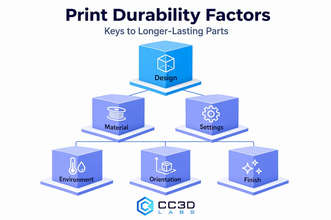
Infographic of main 3D print durability factors

The other thing I would push back on is the assumption that engineering materials automatically solve durability problems. I have watched carbon fiber composites fail on a bracket that was just printed at the wrong angle. The composite stiffness that makes it great in one direction makes it brittle in another. Understanding this is more useful than any spec sheet comparison.

My recommendation for critical applications is to validate your 3D designs before committing to production. Print test coupons in the intended orientation. Load them the way the final part will be loaded. The thirty minutes you spend on that test will tell you more than hours of reading material specs.

— Justin

Get durable 3D printed parts from Cc3dlabs

If this article has you thinking carefully about material selection, orientation, and design for your next project, Cc3dlabs can take that further with hands-on expertise. Based near Philadelphia, Cc3dlabs handles everything from single prototypes to batch production runs, with material knowledge that matches the right filament to the real demands of your application.

https://cc3dlabs.com

Whether you need a structurally sound bracket, a functional prototype that will survive testing, or production parts built for longevity, the team at Cc3dlabs applies the same principles covered here at every step. Explore professional 3D printing services or request a free online estimate to get started with parts that are built to last, not just built.

FAQ

What is the most durable material for 3D printing?

Nylon is the toughest standard thermoplastic for FDM printing, offering high impact resistance and flexibility. Carbon fiber composites provide the highest stiffness and are preferred for structural industrial parts.

Why do 3D printed parts fail along layer lines?

Tensile strength in 3D prints is directional because layer-to-layer bonding is weaker than the material within a layer. Parts loaded across the Z-axis fail first at those inter-layer boundaries.

Does higher infill percentage mean a stronger part?

Not beyond about 20 to 30% infill. Adding more perimeter walls is more effective for resisting crack initiation and surface failure than continuing to increase infill density.

How durable are resin 3D prints compared to filament prints?

Resin parts offer excellent detail but lower impact resistance and fatigue strength than engineering filaments like nylon. Short-term durability is adequate for many uses, but improper post-processing significantly reduces long-term performance.

Can 3D printed parts be used outdoors long-term?

Yes, with the right material. PLA degrades quickly under UV and moisture. ASA, weatherable PETG blends, and properly coated ABS handle outdoor conditions far better, especially when the part design avoids water traps.