Additive manufacturing materials are the substances, ranging from engineering polymers and metal powders to ceramics and fiber-reinforced composites, that 3D printers deposit layer by layer to build a finished part directly from a digital file. The core case for using them is straightforward: the U.S. Department of Energy reports that additive manufacturing can reduce energy use significantly and lower material and waste costs substantially compared to traditional methods. That combination of efficiency and design freedom is why engineers, product developers, and manufacturers across the country are shifting to additive processes for everything from aerospace brackets to medical implants.
The five main material categories are:
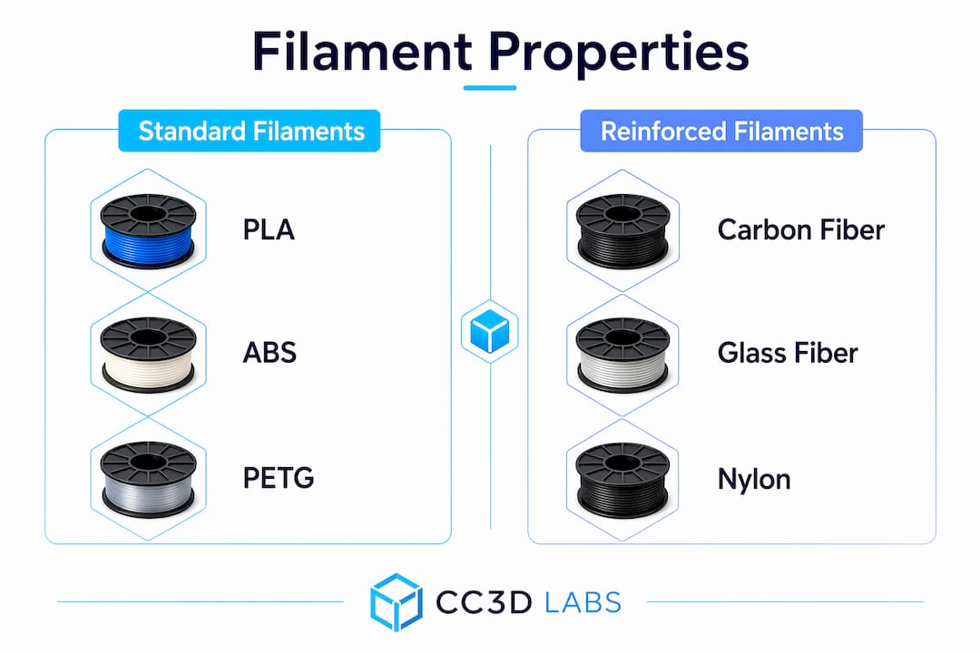
- Polymers (PLA, ABS, PETG, nylon, TPU): the most widely used group, covering prototypes and functional end-use parts
- Metal powders and wires (titanium, stainless steel, Inconel, aluminum alloys): for structural, high-temperature, and load-bearing applications
- Composites (carbon fiber or glass fiber reinforced polymers): higher stiffness and strength-to-weight ratios than base polymers alone
- Ceramics (alumina, zirconia): suited for heat shields, dental restorations, and electronic substrates
- Sand and binder-jetting materials: used primarily for casting molds and cores in foundry applications
Industry bodies including ASTM International and ISO/TC 261 publish the standards that govern how these materials are tested and qualified for production use.
What types of additive manufacturing materials are available?
Understanding the material options is the first step toward choosing the right one for a given application. Each category has a distinct performance profile, and picking the wrong one wastes both time and money.
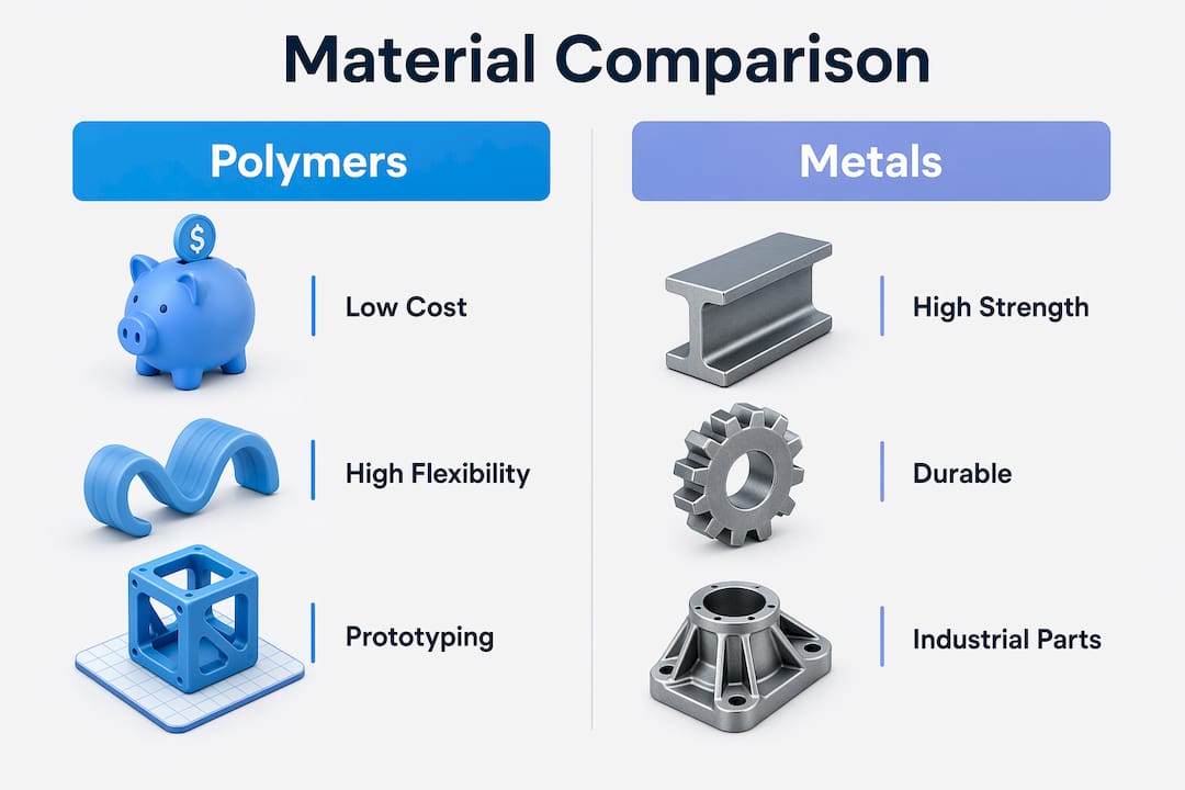
| Material | Typical strength | Flexibility | Relative cost | Common applications |
|---|---|---|---|---|
| Polymers (PLA/ABS) | Low–medium | Medium–high | Low | Prototypes, housings, jigs |
| Engineering polymers (nylon, PEEK) | Medium–high | Low–medium | Medium | Functional parts, brackets |
| Metal powders (Ti, SS, Inconel) | High | Low | High | Aerospace, medical implants |
| Composites (CFRP) | Very high | Low | Medium–high | Structural, motorsport parts |
| Ceramics | High (brittle) | Very low | High | Heat shields, dental, electronics |
| Sand/binder-jet | N/A | N/A | Low–medium | Casting molds and cores |
Polymers dominate prototyping because they are inexpensive, easy to process, and available in a wide range of mechanical properties. Flexible grades like TPU handle living hinges and gaskets; rigid engineering grades like PEEK withstand continuous service above 200°C.
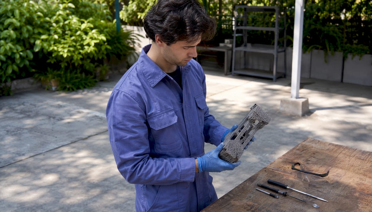
Metal powders unlock the full potential of additive processes for industrial parts. Powder bed fusion (PBF) and directed energy deposition (DED) can produce titanium or Inconel components with internal lattice structures and cooling channels that no subtractive process could replicate. The trade-off is cost: metal feedstock and machine time are expensive, which pushes metal AM toward low-volume, high-value parts.
Composites bridge the gap between polymer accessibility and metal performance. Continuous carbon fiber reinforcement, deposited alongside a nylon or PETG matrix, can produce parts that rival aluminum in stiffness at a fraction of the weight. Aerospace and motorsport teams have adopted this approach for brackets, ducts, and structural panels.
Ceramics and sand occupy specialized niches. Ceramic AM produces dental crowns and heat-resistant components with geometries impossible to achieve by traditional pressing or slip casting. Sand binder jetting prints mold cavities overnight that would take a pattern shop days to machine, compressing foundry lead times dramatically.
Pro Tip: When selecting a material, start with the end-use environment, not the printer. A part that must survive 150°C and chemical exposure needs PEEK or a metal, not PLA, regardless of how convenient PLA is to print.
Why use additive materials? The core advantages
The benefits of additive materials in manufacturing go well beyond “you can print complex shapes.” Each advantage connects to a measurable outcome in cost, time, or performance.
Design freedom that traditional processes cannot match
Additive processes build geometry by addition, so internal channels, lattice infill, and organic topology-optimized shapes are no harder to produce than a solid block. Topology optimization, which uses software to remove material from low-stress regions while preserving load paths, can reduce part weight substantially across multiple industries according to comparative lifecycle studies. Lighter parts mean lower fuel consumption in aerospace and automotive applications, which creates environmental and operating-cost benefits that extend well beyond the factory floor. You can read more about how design-for-manufacturing principles apply to this in Cc3dlabs’s guide on DFM in 3D printing.
Material efficiency that subtractive methods cannot approach
Subtractive manufacturing such as CNC milling can waste a large majority of the starting billet, particularly in aerospace applications where titanium billets are machined down to thin-walled brackets. Additive processes typically achieve high material utilization rates, depositing material only where the geometry requires it. That gap in buy-to-fly ratio is one of the clearest economic arguments for additive materials when feedstock is expensive.
Tooling cost elimination for low-volume production
Traditional injection molding or die casting requires hard tooling that can exceed 80% of total production costs for a given part. Additive manufacturing skips that step entirely. No mold, no die, no fixture. For production runs below roughly 1,000 parts per year, this makes additive the cost-effective choice in most geometries. Aerospace, medical, defense, and energy sectors recognized this early because they routinely produce high-mix, low-volume parts where tooling amortization would be prohibitive.
Supply chain simplification through localized production
Localized additive manufacturing reduces dependence on distant suppliers by enabling on-demand production close to the point of use. Instead of warehousing thousands of spare parts, a facility can store digital files and print what it needs when it needs it. That shift cuts inventory carrying costs and reduces the risk of supply disruption, a lesson that became painfully clear to many U.S. manufacturers during recent global logistics crises.
Sustainability advantages at the right production scale
- Additive processes generate less scrap than subtractive methods, reducing raw material extraction and disposal burdens.
- Eliminating tooling removes the energy and emissions embedded in mold manufacturing.
- Lighter parts produced through topology optimization reduce fuel consumption during a product’s service life.
- AM has lower environmental impacts than traditional manufacturing when production volumes are low or part geometry would cause high material waste conventionally.
Key figure: The U.S. Department of Energy reports additive manufacturing can cut waste and material costs by up to 90% compared to traditional production.
What is driving the development and adoption of additive materials?
The growth of additive materials is not happening in a vacuum. Several converging forces are pushing manufacturers, product developers, and researchers to invest in this technology.
- Demand for customization. Consumer and industrial markets increasingly expect products tailored to specific users or operating conditions. Additive materials make one-off or small-batch customization economically viable without the penalty of tooling costs.
- Rapid prototyping pressure. Shortening development cycles is a competitive necessity. Additive processes compress the time from CAD file to physical part from weeks to hours, letting engineering teams iterate faster and catch design flaws earlier.
- Advances in printer capability. Multi-material printers, higher-temperature build chambers, and in-situ monitoring systems have expanded the range of materials that can be processed reliably. Machine learning and digital twins are now accelerating process stabilization and reducing qualification lead times.
- Lightweighting requirements in aerospace and automotive. Electrification of vehicles increases the premium on structural weight reduction because battery mass must be offset elsewhere. Additive materials, combined with topology optimization, deliver weight savings that material substitution alone cannot achieve.
- Regulatory and sustainability pressure. U.S. and international regulations on emissions and waste are pushing manufacturers toward processes that use less material and generate less scrap. Additive materials align with those goals at appropriate production scales.
- Declining system and material costs. Between 2001 and 2011, the average price of additive manufacturing systems fell 51% after adjusting for inflation. That trend has continued, broadening access beyond aerospace and defense to mid-market manufacturers and startups.
The industries that adopted additive materials earliest, aerospace, medical, and defense, share a common profile: high part complexity, low production volumes, and high material value. Automotive and heavy transportation followed as lightweighting needs intensified. Dental and jewelry sectors adopted additive processes because personalization commands a price premium that justifies the per-unit cost. Each new sector that crosses over expands the material ecosystem and drives further cost reductions.
Research findings and U.S. industrial examples that show real-world impact
The performance claims around additive materials are well-documented, but the nuances matter as much as the headline numbers.
Energy and waste savings: what the data actually shows
The U.S. Department of Energy’s figures, up to 25% energy reduction and up to 90% material cost savings, represent the upper bound of what is achievable under favorable conditions. Those conditions are low production volume, complex part geometry, and expensive feedstock. A systematic review of comparative lifecycle studies found that AM has lower environmental impacts than traditional manufacturing when annual production volumes stay below approximately 1,000 parts, or when the part geometry would generate high material waste if machined conventionally. At higher volumes, the calculus flips: slow build rates and energy-intensive feedstock production can make additive processes less efficient than injection molding or stamping.
Industrial case study: on-site maintenance manufacturing
An industrial maintenance application documented by Kennametal demonstrated what on-site additive manufacturing can deliver in practice. Producing replacement parts additively rather than through traditional machining and forging reduced part weight by 50% and cut emissions by 45%. Those results came from combining topology-optimized designs with metal AM, exactly the kind of geometry-plus-process pairing that makes additive materials most effective.
The hidden costs engineers need to account for
Additive manufacturing carries costs that do not show up in a simple part-weight comparison. Feedstock production and post-processing are both energy-intensive and can significantly increase the environmental footprint of an additively manufactured part. Metal powder atomization, support structure removal, heat treatment, and surface finishing all add time, labor, and energy. Studies that omit these steps from their scope tend to overstate the sustainability advantage of additive processes. A complete cradle-to-gate analysis, covering feedstock, build phase, and post-processing, is the only reliable way to compare additive and traditional routes.
Design knowledge as a prerequisite
Realizing the full benefits of additive materials requires topology optimization and design-for-AM approaches that most engineers trained on subtractive processes have not yet internalized. Internal lattice structures, self-supporting geometries, and integrated cooling channels are not default outputs of conventional CAD workflows. Organizations that invest in this design knowledge consistently outperform those that simply substitute additive for subtractive without redesigning the part. Cc3dlabs’s manufacturing-grade 3D printing guide covers how these design principles translate into production-ready parts.
The honest picture of additive materials is one of genuine, well-documented advantages bounded by real constraints. The technology is not universally superior to traditional manufacturing. It is specifically superior for complex geometries, low volumes, expensive materials, and applications where design freedom creates downstream performance gains. Understanding where those boundaries sit is what separates engineers who get results from those who get expensive prototypes.
Key Takeaways
Additive manufacturing materials deliver their greatest advantages at low production volumes, with complex geometries, and when design freedom is used to reduce weight and eliminate tooling costs.
| Point | Details |
|---|---|
| Material utilization advantage | Additive processes achieve utilization rates above 90%; subtractive methods can waste up to 90% of starting material. |
| Energy and cost savings | The U.S. Department of Energy reports up to 25% energy reduction and up to 90% material cost savings versus traditional methods. |
| Tooling cost elimination | Tooling can exceed 80% of total production costs in injection molding; additive manufacturing removes that expense entirely. |
| Optimal production volume | AM is most cost-effective and environmentally favorable at roughly 1,000 parts per year or fewer, or for high-waste geometries. |
| Hidden costs require full analysis | Feedstock production and post-processing are energy-intensive; a complete lifecycle assessment is needed for accurate comparison. |
Put additive materials to work for your next project

Cc3dlabs operates near Philadelphia and specializes in filament-based 3D printing, multi-material production, and metrology-grade scanning for businesses, product developers, and engineers across the U.S. Whether you need a single functional prototype or a batch of production parts, the team works from your CAD file to a finished, inspected part with fast turnaround. Explore the full range of professional 3D printing services or get a free online estimate to see what additive materials can do for your specific application.