Product developer working on prototype sketches

What Is Iterative Prototyping for Product Developers


TL;DR:

  • Iterative prototyping is a cyclic process of building, testing, and refining prototypes to reduce uncertainty and improve product quality. It enables faster learning, stakeholder alignment, and cost savings by validating assumptions early and continuously throughout development. Proper fidelity selection and hypothesis framing are crucial to maximizing the benefits of each iteration cycle.

Iterative prototyping is defined as a cyclic process of building, testing, and refining prototypes to progressively improve a product’s quality and alignment with user needs. Each cycle produces documented learning that drives the next version forward. Methodologies like Agile, Lean Startup, and the Build-Measure-Learn loop all depend on this principle. Prototype fidelity ranges from paper sketches and Figma wireframes to functional 3D-printed models, and choosing the right level at each stage determines how much useful feedback you actually collect.

What is iterative prototyping and why does it matter?

Iterative prototyping is the structured practice of creating a prototype, exposing it to real testing conditions, analyzing what you learn, and feeding those findings directly into the next version. It is not a single event. It is a repeating cycle where each pass reduces uncertainty and sharpens the product’s direction.

The core value is risk reduction. Changes made early in development cost a fraction of what they cost after manufacturing or launch. A team that discovers a critical ergonomic flaw in a third-iteration 3D-printed model avoids the far greater expense of retooling production parts. This is why product teams at companies like Apple, IDEO, and Google have embedded iterative cycles into their standard development workflows.

Iterative prototyping also separates assumption from evidence. Before you test a physical or digital prototype, your product concept is a collection of guesses. After testing, it becomes a set of validated decisions. That shift from assumption to evidence is what iterative methods provide that sequential, waterfall approaches cannot.

“Prototypes shift stakeholders from imagining to observing and reacting to concrete designs, improving feedback specificity and decision-making.” — Medium, Prototyping Insights

The benefits of iterative prototyping extend beyond error prevention:

  • Faster learning cycles. Short sprint-based iterations surface problems in days or weeks rather than months.
  • Stakeholder alignment. Physical or interactive prototypes replace abstract descriptions with tangible objects, making feedback concrete and specific.
  • Reduced development cost. Catching structural or usability issues before production tooling saves significant budget.
  • Higher product-market fit. Repeated user testing ensures the final product reflects real needs, not internal assumptions.

Pro Tip: Set a clear learning objective before each prototype cycle. “Does this grip feel comfortable for extended use?” is a testable question. “Is this good?” is not. Specific questions produce specific answers.

How does the iterative prototyping cycle work?

The iterative design process follows a repeating four-step cycle. Understanding each step prevents teams from treating iteration as a vague concept and helps them execute it with discipline.

  1. Build the prototype. Create a version of the product or feature at the fidelity level appropriate to your current question. This could be a paper sketch, a foam model, a Figma mockup, or a functional 3D-printed part.
  2. Test with real users or stakeholders. Expose the prototype to the people who will actually use or evaluate the product. Observe behavior rather than just collecting opinions.
  3. Analyze the feedback. Identify patterns in what users struggled with, misunderstood, or responded positively to. Separate signal from noise.
  4. Refine and repeat. Apply findings to the next version. Document what changed and why, so the team builds institutional knowledge rather than cycling through the same problems.

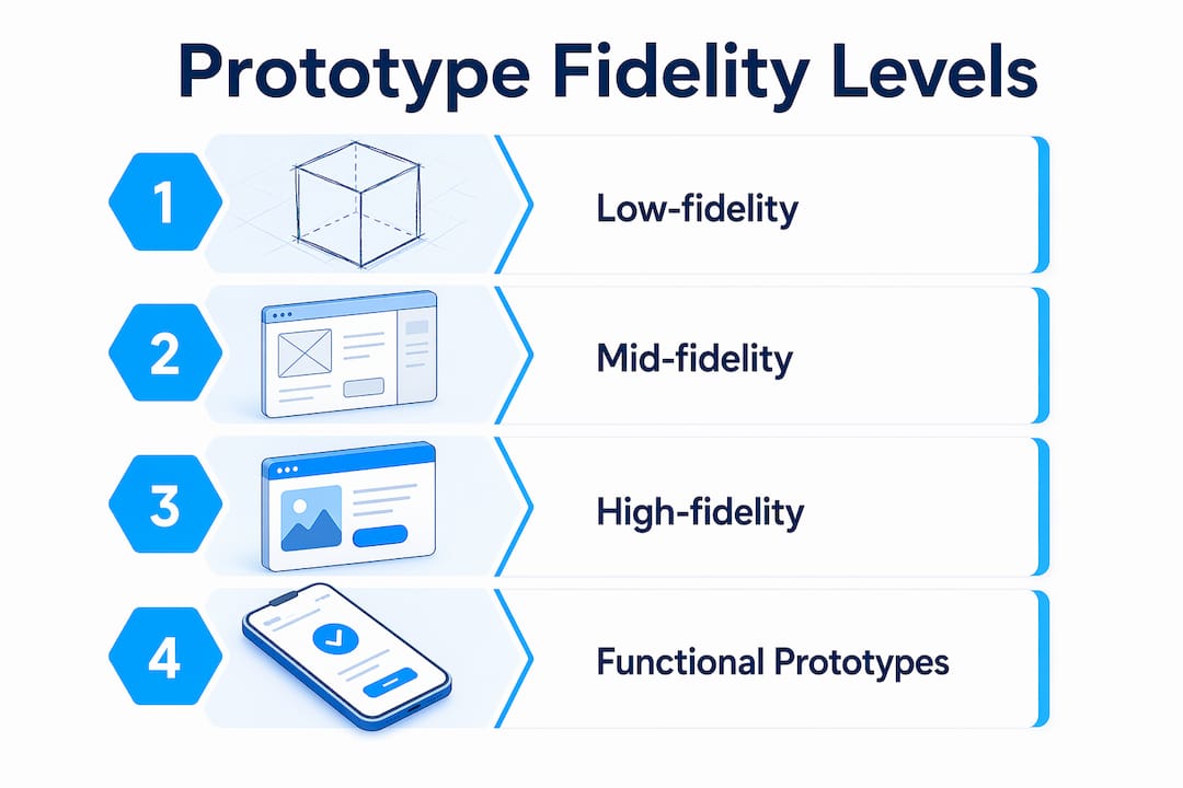
Fidelity selection is where many teams make costly mistakes. Low-fidelity prototypes deliver the largest leverage early in development because they validate structure and core concepts before any significant investment is made. A paper sketch of a product’s assembly sequence costs an hour to create and can reveal fundamental workflow problems. A polished CAD render of the same product costs days and tends to attract feedback about surface finish rather than function.

The table below shows how fidelity maps to the type of question you should be asking at each stage:

Fidelity level Best for Example format
Low fidelity Validating flow, structure, and core concept Paper sketches, foam models, rough wireframes
Mid fidelity Testing layout, navigation, and component relationships Figma wireframes, basic 3D-printed shells
High fidelity Evaluating interaction, realism, and final usability Functional 3D-printed parts, interactive digital prototypes

Infographic showing prototyping fidelity levels

Engineer inspecting 3D printed prototype on workbench

Matching fidelity to uncertainty type optimizes both learning quality and resource use. Premature high-fidelity prototypes shift stakeholder attention to visual polish and away from the structural or usability questions that actually matter at that stage.

Pro Tip: When you move to high-fidelity physical prototypes, filament-based 3D printing gives you functional geometry at a fraction of injection-molded cost. You can test snap fits, wall thickness, and ergonomics before committing to hard tooling.

How iterative prototyping fits into Agile, Lean, and rapid development

Iterative prototyping does not exist in isolation. It is the practical engine inside the frameworks that modern product teams already use.

In Agile development, work is divided into sprints that permit feedback and adaptation at multiple stages. Prototyping within Agile serves as a discovery mechanism that runs ahead of or alongside development sprints. A team building a new hardware product might prototype the physical enclosure in parallel with firmware development, using each sprint review to validate both dimensions simultaneously.

Lean Startup’s Build-Measure-Learn loop is structurally identical to iterative prototyping. Build the simplest version that tests your riskiest assumption. Measure real user response. Learn whether to pivot or continue. The critical discipline in this loop is shortening iteration cycles to weeks rather than months, which compresses the time between assumption and validated knowledge.

Agile rapid prototyping treats prototypes explicitly as learning tools rather than deliverables. This is a meaningful distinction. A deliverable is judged by its finish quality. A learning tool is judged by the quality of the insight it generates. Teams that confuse the two tend to over-invest in prototype polish and under-invest in structured testing.

The contrast with waterfall development is stark. In a traditional waterfall process, prototyping happens once, early, and feeds into a specification that drives the entire build. Feedback arrives late, when changes are expensive. Iterative approaches distribute feedback across the entire development timeline, so validated learnings continuously feed back into the product backlog and refinement decisions.

You can explore the broader context of rapid prototyping frameworks to see how iterative cycles connect to manufacturing-ready development pipelines.

Common pitfalls in iterative prototyping and how to avoid them

Iterative prototyping produces results only when each cycle generates genuine learning. Several common patterns prevent that from happening.

  • Faster waterfall thinking. Without framing each cycle as a testable hypothesis, iteration risks becoming a faster version of sequential development. You produce more versions but reduce no more uncertainty. The fix is to define a specific question before each build, not after.
  • Confusing visual polish with design quality. A prototype that looks finished tends to receive feedback about aesthetics rather than function. Teams that present high-fidelity visuals too early get comments on color and typography when they need answers about usability and structure.
  • Skipping documentation. Each iteration should produce a written record of what was tested, what was learned, and what decision was made. Without this, teams repeat the same experiments across cycles and lose institutional knowledge when team members change.
  • Collecting vague feedback. Prototypes work best as conversation tools that generate honest, specific assessments. Asking “What do you think?” produces vague commentary. Asking “Walk me through how you would assemble this” produces observable behavior and concrete insights.
  • Ignoring risk prioritization. Risk exposure should determine when and what to prototype. Prototype the highest-impact uncertainties first. Spending iteration cycles on low-risk details while structural assumptions remain untested is a common and expensive mistake.

Pro Tip: Before each iteration, write one sentence: “We believe [X]. We will test this by [Y]. We will know we are right if [Z].” This single habit eliminates vague iteration and produces decisions, not just versions.

Key takeaways

Iterative prototyping works because each cycle converts assumptions into validated decisions, and that compounding knowledge is what separates products that ship right from products that ship and fail.

Point Details
Define the cycle clearly Build, test, analyze, and refine in documented cycles that produce specific decisions.
Match fidelity to the question Use low-fidelity prototypes early for structure; reserve high-fidelity for interaction and realism testing.
Frame each iteration as a hypothesis Write a testable claim before each build to avoid cycling without reducing uncertainty.
Integrate with Agile and Lean Prototyping serves as the discovery engine inside sprints and Build-Measure-Learn loops.
Prioritize by risk exposure Prototype the highest-impact unknowns first to allocate effort where it reduces the most uncertainty.

Why fidelity decisions are the real skill in iterative prototyping

Most articles on iterative prototyping focus on the cycle itself. The harder skill, in my experience, is fidelity judgment. I have watched teams spend three weeks building a polished interactive prototype to answer a question that a two-hour paper sketch would have resolved. The result was not just wasted time. It was distorted feedback, because stakeholders reacted to the visual finish instead of the underlying structure.

The insight that changed how I think about this came from working on a physical product enclosure. We had two competing assembly approaches. Instead of modeling both in CAD, we built foam mockups in an afternoon. Users immediately showed us which approach created confusion during assembly. That single session saved weeks of CAD revision and tooling cost.

The other pattern I see consistently is teams treating iteration as output production rather than learning production. They measure success by how many versions they shipped rather than how many assumptions they resolved. The hypothesis-driven framing from Jasiri’s iterative design research is the most practical correction I know. Write the hypothesis. Run the test. Document the outcome. If you cannot state what you learned from a cycle, the cycle did not count.

For physical product teams, 3D printing has genuinely changed the economics of high-fidelity iteration. The ability to validate 3D designs with functional printed parts before committing to tooling is not a minor convenience. It compresses what used to be a months-long feedback loop into days.

— Justin

Accelerate your iterations with professional 3D printing

Physical prototypes close the gap between digital design and real-world performance faster than any other method. When your iteration cycle depends on functional parts, material accuracy, and fast turnaround, the quality of your printing service directly affects the quality of your learning.

https://cc3dlabs.com

Cc3dlabs, based near Philadelphia, provides professional 3D printing services built for product developers who iterate fast. From filament-based functional prototypes to multi-color concept models, Cc3dlabs supports every fidelity level your development cycle requires. You can get a free online estimate, request design support, or ship parts directly to your team. If you want to understand how 3D printing drives product innovation at each stage of development, Cc3dlabs has the capability and the expertise to support your next iteration.

FAQ

What is iterative prototyping in product development?

Iterative prototyping is a cyclic process of building a prototype, testing it, analyzing feedback, and refining the design across multiple rounds. Each cycle reduces uncertainty and improves product quality before final production.

How many iterations does a typical prototype cycle require?

There is no fixed number. The cycle continues until the highest-priority uncertainties are resolved and the product meets validated user and performance requirements. Most hardware products go through three to seven major iteration cycles before production readiness.

What is the difference between low-fidelity and high-fidelity prototypes?

Low-fidelity prototypes validate structure, flow, and core concepts using minimal resources, such as paper sketches or foam models. High-fidelity prototypes test realistic interaction and final usability using functional models or detailed digital mockups.

How does iterative prototyping connect to Agile methodology?

Agile divides development into sprints that allow feedback and adaptation at each stage. Iterative prototyping functions as the discovery mechanism within those sprints, testing assumptions before they become expensive development commitments.

What is the biggest mistake teams make in iterative prototyping?

The most common mistake is iterating without a defined hypothesis, which turns the process into a faster version of sequential development without genuine uncertainty reduction. Each cycle must begin with a specific, testable question to produce real learning.
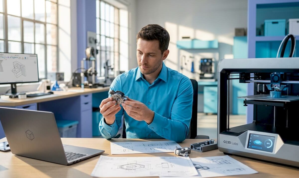
Developer inspecting physical functional prototype

What Is Functional Prototyping for Product Developers


TL;DR:

  • Functional prototyping involves creating operational models that produce measurable engineering data before manufacturing begins. It encompasses methods like CNC machining, 3D printing, and sheet metal fabrication, chosen to match specific validation goals and performance parameters. This process is essential for reducing design risks, verifying fit, strength, and thermal performance, and accelerating product development through iterative testing.

Functional prototyping is defined as the process of building physical or digital models that replicate a product’s production-intent form, fit, and function closely enough to generate valid engineering data before full-scale manufacturing begins. Unlike appearance models or concept sketches, a functional prototype must perform. It carries load, transfers motion, conducts current, or executes software logic under conditions that mirror real use. Methods like CNC machining, filament-based 3D printing, and hybrid software prototyping each serve distinct validation goals, and choosing the right one determines whether your test data is trustworthy or misleading.

What is functional prototyping and how does it differ from other types?

Functional prototyping is the practice of replicating production geometry, material behavior, and assembly interfaces in a working model to produce test data that drives production decisions. The word “functional” is the operative distinction. A prototype that looks right but cannot be loaded, cycled, or measured tells you almost nothing about whether your design will survive manufacturing and real-world use.

Three prototype categories define the spectrum product teams work across:

  • Appearance prototypes replicate visual form and surface finish but use no production-equivalent materials or tolerances. They are useful for marketing reviews and investor presentations, not engineering sign-off.
  • Proof-of-concept models demonstrate a principle works at a basic level, often with off-the-shelf components and rough geometry. They answer “can this work?” not “will this work at scale?”
  • Functional prototypes incorporate production-representative materials, controlled tolerances, and realistic assembly interfaces. They answer measurable questions: Does this joint hold 200 N of force? Does this housing dissipate heat within spec? Does this software flow handle 500 concurrent users?
Prototype type Material accuracy Tolerance control Test capability
Appearance model Low Low Visual review only
Proof-of-concept Moderate Low Principle validation
Functional prototype High High Engineering and performance testing

The table makes the trade-off clear. Functional prototypes cost more to produce than appearance models, but they replace design assumptions with measured test data under controlled conditions. That trade-off is almost always worth it before committing to production tooling.

What manufacturing methods are used in functional prototyping?

The method you choose to build a functional prototype determines the quality of the data you get back. Three manufacturing approaches dominate the field, each suited to different validation objectives.

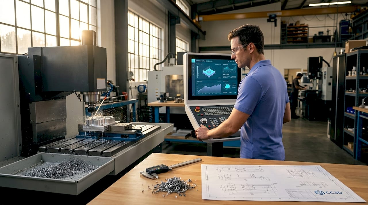
CNC machining of prototype part in workshop

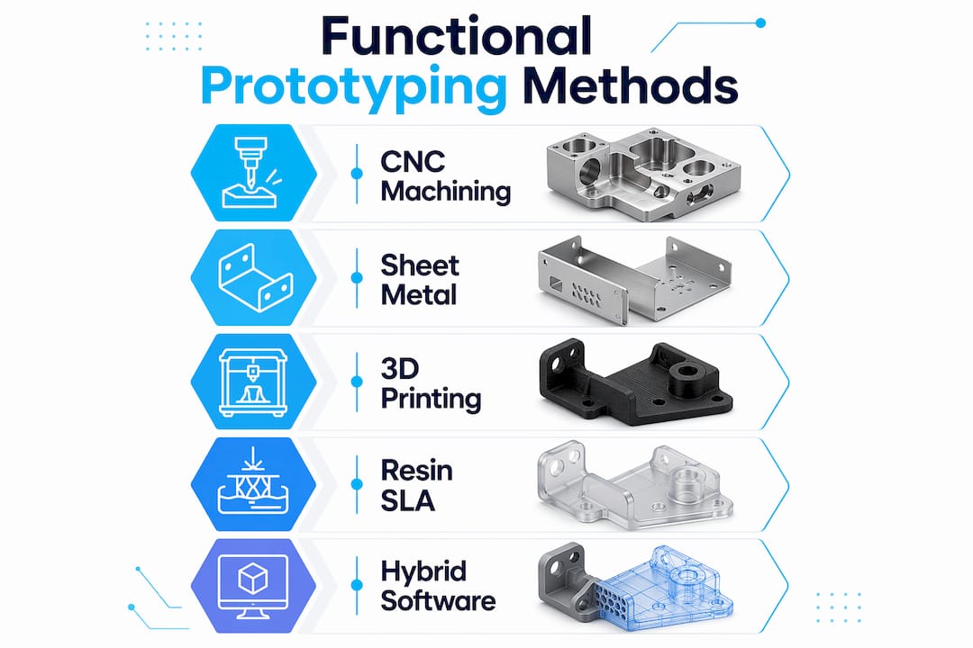
CNC machining is the standard for load-bearing and safety-critical parts. CNC rapid prototyping produces parts from production-grade metals and engineering plastics with realistic tolerances, making it the right choice when you need to test fit, fatigue, or manufacturability under real conditions. A medical device housing, an automotive bracket, or a hydraulic manifold all demand CNC-level dimensional accuracy before you can trust the test results.

Sheet metal fabrication serves structural assemblies where wall thickness, bend radius, and weld joint behavior must be validated. Enclosures, frames, and chassis components built from sheet metal prototypes reveal assembly interference and structural compliance issues that no simulation catches reliably.

3D printing covers the widest range of functional prototyping scenarios where rapid iteration outweighs the need for full production realism. Filament-based FDM printing with materials like PETG, ASA, or Nylon produces parts that withstand mechanical loading, thermal cycling, and chemical exposure well enough for early-stage validation. Resin-based SLA printing delivers finer feature resolution for snap-fit mechanisms and optical components. You can review filament prototype examples to understand how material selection directly affects test outcomes.

Infographic of main functional prototyping manufacturing methods

In software development, functional prototypes move beyond clickable wireframes. Hybrid functional prototyping implements actual backend logic and real data flows, allowing teams to test user behavior and system performance rather than just screen transitions.

Pro Tip: Match your manufacturing method to the specific failure mode you are testing for. If you are validating thermal behavior, material equivalency matters more than surface finish. If you are validating assembly clearance, dimensional accuracy matters more than material strength.

What engineering goals does functional prototyping achieve?

Functional prototypes are test instruments. Every build should map to a specific engineering question, and the answer should come back as a number, not an opinion.

  1. Fit and assembly verification. Mating surfaces, fastener patterns, and clearance envelopes are confirmed against production drawings. This catches interference issues before tooling is cut, where corrections cost orders of magnitude more.
  2. Structural and mechanical performance. Load testing, fatigue cycling, and deflection measurement validate that geometry and material choices meet specification. Performance testing measures output parameters like force, speed, and displacement rather than relying on simulation alone.
  3. Thermal and environmental validation. Prototypes exposed to operating temperature ranges, humidity, and UV confirm that material selection and wall thickness choices hold up. A housing that warps at 60°C in testing saves a costly field recall.
  4. Electrical and software functionality. PCB assemblies and embedded firmware tested in a functional prototype reveal signal integrity issues, power draw anomalies, and timing failures that schematic review misses.
  5. System integration testing. Subsystems assembled together for the first time in a functional prototype reveal interface conflicts between mechanical, electrical, and software domains that individual component tests never surface.

Functional prototyping represents the point where risk becomes measurable, replacing CAD assumptions with data collected under controlled test conditions. That shift from assumption to measurement is the core value of the entire process.

Pro Tip: Replicate the exact mating interfaces and tolerances from your production drawings, not approximations. Effective engineering validation depends on precise interface control. A prototype that fails because of a loose fit you introduced during fabrication teaches you nothing about your design.

Best practices and common pitfalls in functional prototyping

Getting useful data from a functional prototype requires discipline in how you build and test it. The most common mistakes are not about budget or schedule. They are about mismatched fidelity and poor test planning.

  • Match fidelity to the validation objective. A prototype built to test ergonomics does not need production-grade material strength. A prototype built to test fatigue life does. Building every prototype to the highest fidelity wastes resources and slows iteration.
  • Never underestimate material behavior differences. Using production-equivalent materials is critical when validating strength, thermal response, and wear behavior. A PLA prototype tested for heat resistance will fail at temperatures that PETG or Nylon handles without issue, and that failure reflects the material choice, not the design.
  • Control mating surfaces precisely. Loose or oversized interfaces in a prototype introduce false failures. If a seal leaks because the prototype housing is 0.3 mm out of spec, you have learned nothing about your seal design. You have only confirmed that sloppy fabrication produces sloppy results.
  • Plan iteration cycles before you build the first prototype. Building fast and rough versions to test assumptions reduces expensive errors later. Teams that plan three or four iteration cycles from the start converge on viable designs faster than teams that try to get everything right in one expensive build.
  • Manage the cost-versus-realism trade-off deliberately. CNC machining delivers the highest fidelity but costs more per part. 3D printing delivers faster turnaround at lower cost but with material and tolerance limitations. The right answer depends on what you are testing, not on what the budget allows by default.

For software functional prototypes, the equivalent pitfall is building UI flows that look interactive but contain no real logic. Actual backend implementation is what separates a functional software prototype from a clickable mockup, and only the former produces meaningful user behavior data.

Pro Tip: Use your 3D design validation process to define acceptance criteria before fabrication starts. Knowing what pass and fail look like before you run the test prevents post-hoc rationalization of ambiguous results.

Key takeaways

Functional prototyping is the most direct method for replacing design assumptions with engineering data before production tooling commits your budget to a fixed design.

Point Details
Definition is performance-based A functional prototype must generate measurable test data, not just represent the product visually.
Method must match validation goal CNC machining suits load-bearing tests; 3D printing suits rapid iteration; sheet metal suits structural assemblies.
Material equivalency is non-negotiable Using the wrong material class produces test results that do not predict final product performance.
Interface precision prevents false failures Mating surfaces and tolerances must match production drawings to avoid prototype-induced test errors.
Iteration speed drives convergence Planning multiple short build-and-test cycles reaches a viable design faster than one high-cost build.

Why functional prototyping is the most underrated step in product development

Most product teams I work with treat functional prototyping as a checkpoint, something you do once before you hand off to manufacturing. That framing is wrong, and it costs teams real money. Functional prototyping is a learning engine. Every build should answer a specific question, and the answer should change something about the next build.

The industry misconception I see most often is the belief that simulation replaces physical testing. Finite element analysis and CFD are powerful tools, but they model the geometry and material properties you input. A functional prototype tests the geometry and material behavior you actually produced. Those two things are never identical, and the gap between them is where product failures live.

What has changed in 2026 is the accessibility of the methods. Filament-based 3D printing with engineering-grade materials, combined with affordable CNC services and cloud-based CAD tools, means a two-person startup can run the same validation workflow that a Fortune 500 engineering team ran a decade ago. The barrier is no longer equipment access. It is knowing what question to ask and building the prototype that answers it precisely.

The teams that win at product development are not the ones with the biggest prototyping budgets. They are the ones that prototype the right thing, measure the right parameter, and iterate faster than their competitors. That discipline starts with understanding what functional prototyping actually is and what it is not.

— Justin

How Cc3dlabs accelerates your functional prototyping workflow

https://cc3dlabs.com

Cc3dlabs, based near Philadelphia, produces functional prototypes using filament-based 3D printing with engineering-grade materials including PETG, ASA, Nylon, and carbon-fiber-reinforced filaments. Their 3D printing services cover single prototypes through batch production runs, with CAD support and professional handheld 3D scanning (accuracy to ~0.1 mm) available for parts that require dimensional verification after fabrication. For teams that need fast turnaround on on-demand prototype parts without minimum order requirements, Cc3dlabs offers free online estimates and local pickup near Philadelphia or direct shipping. If your validation cycle depends on getting accurate, durable parts quickly, their team is built for exactly that workflow.

FAQ

What is a functional prototype?

A functional prototype is a working model that replicates a product’s production-intent geometry, material behavior, and assembly interfaces closely enough to generate valid engineering test data. It differs from an appearance model by performing under real load, thermal, or operational conditions.

How do functional prototypes differ from proof-of-concept models?

Proof-of-concept models demonstrate that a principle works using rough geometry and off-the-shelf components. Functional prototypes use production-equivalent materials and controlled tolerances to validate whether the design performs to specification under realistic conditions.

What are the most common functional prototyping methods?

CNC machining, filament-based 3D printing, resin SLA printing, and sheet metal fabrication are the primary methods. The right choice depends on the specific performance parameter being tested and the tolerance accuracy required for valid results.

Why is material selection critical in functional prototyping?

Manufacturing processes affect material properties significantly, so prototypes must use production-grade or equivalent materials to accurately validate strength, thermal response, and wear behavior. A prototype built from the wrong material class produces test data that does not predict final product performance.

How many prototyping iterations are typically needed?

The number depends on design complexity and how many subsystems require independent validation, but teams that plan multiple short build-and-test cycles consistently converge on viable designs faster than teams that attempt a single high-fidelity build.

3D printer extruding fine layers of plastic part

Wall Thickness in 3D Printing: A Complete Guide


TL;DR:

  • Wall thickness in 3D printing refers to the solid outer perimeter layers that define a part’s boundary, separate from internal infill. Properly setting wall thickness ensures parts are strong, accurate, and durable, avoiding failures like cracking or warping. It is best designed as a multiple of the nozzle diameter, tailored to the specific material and technology used for optimal print reliability.

Wall thickness in 3D printing is defined as the measurement of the outer solid perimeter layers that form a part’s boundary, separate from the internal infill structure. This single parameter shapes whether a printed part survives real-world use or fails on first contact with stress. Get it wrong and you waste material, time, and filament on a part that cracks, warps, or prints with gaps. Get it right and you unlock prints that are strong, accurate, and built for their intended purpose. This guide covers what wall thickness means, how it interacts with your slicer and material, and how to dial it in for any print.

What is wall thickness in 3D printing?

Wall thickness is the outer shell thickness of a 3D printed part, forming the solid boundary between the part’s surface and its interior infill. It is not the same as infill density, and confusing the two is one of the most common mistakes in print design. Infill fills the interior volume at a chosen density pattern. Wall thickness defines the solid outer frame that holds everything together.

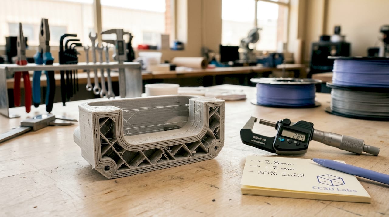
Cross section of 3D printed part walls

Some sources draw a further distinction between wall thickness and shell thickness. Wall thickness refers specifically to the vertical perimeters running along the sides of a part. Shell thickness includes those vertical walls plus the top and bottom solid layers. Understanding this difference matters when you are configuring a slicer, because the two settings are adjusted independently and affect different aspects of part performance.

Wall thickness also connects directly to nozzle diameter and layer height. A printer running a 0.4 mm nozzle extrudes lines of roughly that width, so every wall is built from stacked extrusion lines. This relationship between hardware and geometry is why wall thickness is not just a design choice but a printing parameter with physical constraints.

How wall thickness varies by technology and material

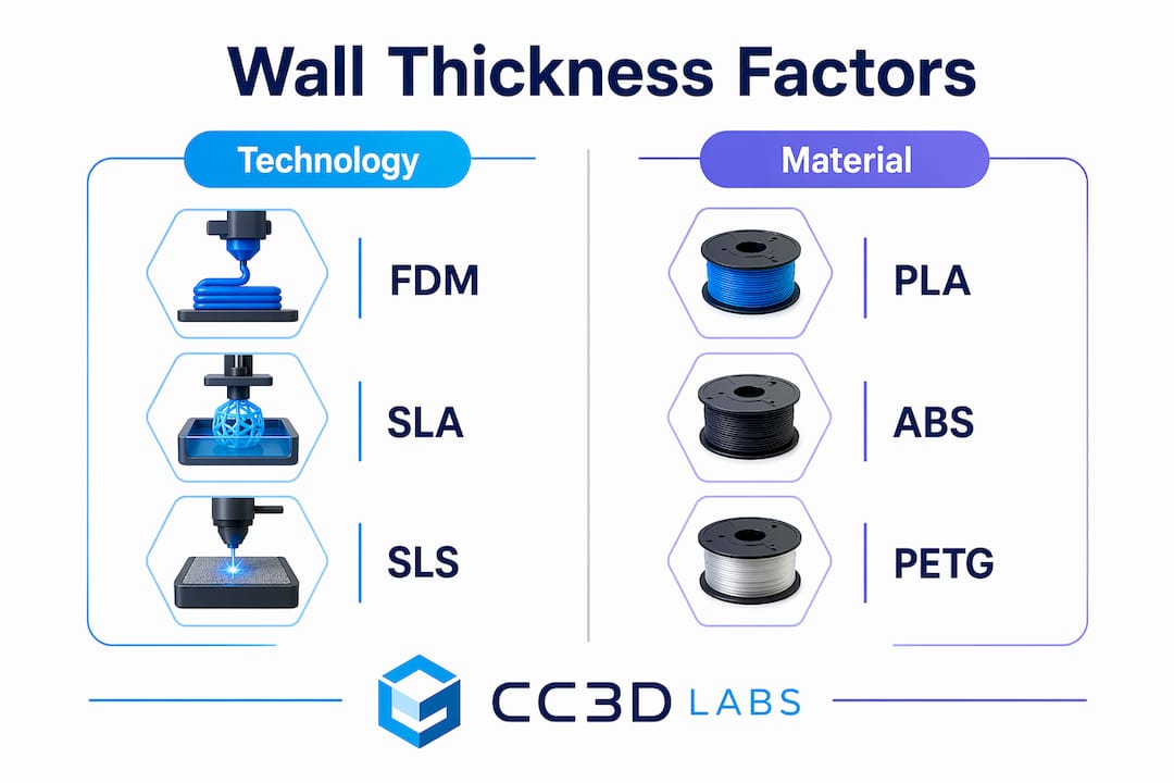
Minimum wall thickness values differ significantly across printing technologies because each process uses different physics to build parts. FDM (Fused Deposition Modeling) typically requires a minimum of 0.8 to 1.2 mm. SLA resin printing can go as thin as 0.5 mm. SLS Nylon powder bed printing sits around 0.7 to 1 mm. Metal DMLS processes require 1 to 2 mm due to thermal stress and sintering behavior.

These differences exist because powder bed and resin technologies support the part during printing, allowing thinner walls without collapse. FDM parts are built layer by layer in open air, requiring more material to maintain structural integrity during the print itself. This means a wall thickness that works perfectly in SLA will fail to print reliably in FDM on the same geometry.

Infographic comparing wall thickness by technology and material

Material choice adds another layer of complexity. PLA is stiff and prints well at thinner walls. ABS and PETG require slightly thicker walls to compensate for their tendency to warp or delaminate under stress. TPU, being flexible, needs thicker walls to maintain shape and resist tearing. Metal and engineering-grade materials demand the most conservative minimums because the consequences of failure are more severe.

The table below summarizes typical minimum wall thickness values by technology:

Technology Material Minimum wall thickness
FDM PLA, ABS, PETG 0.8 to 1.2 mm
SLA Standard resin 0.5 mm
SLS Nylon 0.7 to 1.0 mm
DMLS Metal alloys 1.0 to 2.0 mm
FDM TPU (flexible) 1.5 to 2.0 mm

Load-bearing parts and components that will be post-processed (sanded, painted, or drilled) should always target the upper end of these ranges. Visual models or display pieces can use minimums. The intended function of the part, not just the material, determines where in the range you should land.

Wall thickness vs. wall count vs. shell thickness in slicers

Slicer software like Orca Slicer, PrusaSlicer, and Bambu Studio each use slightly different terminology, but the underlying concepts are consistent. Understanding how these three terms relate to each other prevents costly misconfigurations.

Here is how the terms break down:

  1. Wall thickness is the total width of the outer perimeter. It equals the number of wall lines multiplied by the extrusion width.
  2. Wall count (also called perimeter count or wall line count) is the number of extrusion lines that form the outer shell. A 0.5 mm nozzle printing a 1.5 mm wall uses 3 wall lines.
  3. Shell thickness is the broader term that includes both the vertical walls and the top and bottom solid layers. Adjusting shell thickness in a slicer changes how many solid layers cap the top and bottom of the part.

For a 0.4 mm nozzle, a wall count of 2 produces a wall thickness of approximately 0.8 mm. A wall count of 3 produces 1.2 mm. This is why designing walls as multiples of the nozzle diameter avoids gaps and weak points in the perimeter. A wall designed at 1.0 mm with a 0.4 mm nozzle forces the slicer to either squeeze in 2.5 lines (impossible) or adjust the extrusion width, which can introduce inconsistencies.

Slicers also enforce minimum printable widths. When a wall in your model is thinner than the nozzle diameter, the slicer may omit or adjust it entirely, creating a discrepancy between your CAD design and the actual printed part. This is a frequent source of confusion when thin features disappear in the print preview.

Pro Tip: Set your wall thickness to an exact multiple of your nozzle diameter before slicing. For a 0.4 mm nozzle, use 0.8 mm, 1.2 mm, or 1.6 mm. This eliminates extrusion width adjustments and produces the most consistent perimeters.

How wall thickness affects strength, durability, and print reliability

Walls are the primary structural framework of any 3D printed part. Thicker walls strengthen parts more reliably than increasing infill alone, because the outer perimeters carry the majority of bending, tensile, and compressive loads. A part with 15% infill and 3 wall lines will outperform a part with 50% infill and 1 wall line in most real-world load scenarios.

The risks of getting wall thickness wrong fall into two categories:

  • Too thin: Walls below the technology minimum produce incomplete perimeters, visible gaps, delamination under stress, and failed prints. Thin walls on FDM parts are especially vulnerable to layer separation when the part is flexed or dropped.
  • Too thick: Walls that are excessively thick increase print time, material cost, and part weight without proportional strength gains. They can also cause warping in materials like ABS because the greater mass retains heat unevenly during cooling.

Wall thickness also interacts with post-processing. Parts that will be sanded, drilled, or threaded need extra wall material to survive the process without breaking through to infill. A threaded insert pressed into a wall thinner than 2 mm will crack the perimeter. For heat-resistant applications, thicker walls slow thermal transfer and protect the part’s geometry under sustained load.

“Wall thickness should be treated as a primary design variable, with infill secondary, to ensure structural integrity.” — BigRep Design Guide

Pro Tip: For functional parts that will experience repeated stress, use a minimum of 3 wall lines regardless of material. This creates a perimeter thick enough to distribute load across multiple extrusion paths rather than concentrating stress on a single line.

For a deeper look at how infill patterns and wall settings work together, the infill and strength guide at Cc3dlabs covers the interaction in detail.

How to measure and optimize wall thickness in your designs

Measuring wall thickness starts in your CAD software before the file ever reaches a slicer. Tools like Fusion 360, SolidWorks, and FreeCAD all include wall thickness analysis features that flag areas below a specified minimum. Running this check before export catches problems that would otherwise only appear as failed prints.

Once in the slicer, the preview mode shows exactly how walls are being interpreted. Thin wall detection in Orca Slicer and PrusaSlicer highlights areas where the slicer has modified or dropped wall lines. These highlighted zones are where your print will be weakest.

Follow these steps to optimize wall thickness systematically:

  • Start with nozzle multiples. Set your initial wall thickness to 2x or 3x your nozzle diameter and adjust from there based on part function.
  • Run a test print. Print a small cross-section of your part’s most complex geometry before committing to a full print. This reveals slicer behavior in tight areas.
  • Check wall distribution in complex geometry. Curved surfaces and narrow features cause slicers to adjust effective wall width locally. Review the layer preview at multiple heights.
  • Use a minimum wall thickness calculator for engineering parts. These tools factor in material, process, and feature size to recommend a practical minimum that avoids manufacturing defects.
  • Iterate with purpose. Change one variable at a time. Adjust wall count, reprint the test section, and evaluate before changing material or layer height.

For parts with varying cross-sections, such as brackets with thin flanges and thick bosses, consider using variable wall thickness in your CAD model rather than relying on a single slicer setting. This gives you precise control over where material is concentrated and where it is not.

Pro Tip: When designing for reliable prototypes and functional parts, model your wall thickness explicitly in CAD rather than relying on slicer wall count settings alone. Explicit geometry gives you full control and eliminates slicer interpretation errors.

Key takeaways

Wall thickness is the single most important structural variable in 3D print design, and setting it as a multiple of nozzle diameter while matching it to your technology and material is the fastest path to reliable, strong parts.

Point Details
Wall thickness definition The outer solid perimeter of a printed part, distinct from infill and shell top/bottom layers.
Technology-specific minimums FDM needs 0.8 to 1.2 mm; SLA can use 0.5 mm; DMLS metals require 1 to 2 mm.
Nozzle diameter rule Design walls as exact multiples of nozzle diameter to prevent gaps and slicer adjustments.
Walls over infill for strength Three wall lines outperform high infill for load-bearing parts in most stress scenarios.
Measure before you print Use CAD wall analysis and slicer preview tools to catch thin-wall issues before the first layer.

Why wall thickness is the variable most designers underestimate

After working with hundreds of 3D printed parts across FDM, SLA, and SLS processes, the pattern I see most often is this: designers spend hours tuning infill density and layer height, then set wall count to 2 and wonder why the part breaks. Wall thickness is not a secondary setting. It is the structural backbone of the print.

The misconception that infill drives strength is persistent and understandable. Infill is visible in slicer previews, it has named patterns (gyroid, honeycomb, grid), and it feels like the “meat” of the part. But the walls are what transfer load from the surface to the interior. A part with thin walls and dense infill is like a building with thick floors and paper-thin exterior walls. The interior can be solid, but the structure still fails at the boundary.

What I have found in practice is that most functional parts benefit from 3 to 4 wall lines, regardless of material. This is not a universal rule, but it is a reliable starting point that holds across PLA, PETG, and ABS. For flexible materials like TPU, I go to 5 or 6 lines because the flex itself distributes stress across the perimeter in ways that thinner walls cannot absorb.

The other thing most guides skip is the interaction between wall thickness and post-processing. If you plan to sand, paint, or insert hardware into a part, you are removing or stressing material that the slicer assumed would be there. Add at least one extra wall line for any part that will be post-processed. It costs almost nothing in print time and prevents a frustrating reprint.

For anyone dealing with material-specific wall challenges, the practical advice is always the same: test a cross-section first, measure the result, and adjust before printing the full part.

— Justin

Get expert wall thickness guidance from Cc3dlabs

Cc3dlabs brings professional-grade expertise to every print, including the wall thickness decisions that determine whether a part performs or fails.

https://cc3dlabs.com

Whether you are prototyping a functional bracket, producing a batch of custom enclosures, or validating a design before manufacturing, Cc3dlabs’ team near Philadelphia handles the full process. From material selection and wall thickness optimization to multi-color FDM and professional handheld 3D scanning (accuracy to ~0.1 mm), every project gets the attention it needs to print right the first time. Explore professional 3D printing services at Cc3dlabs and get a free online estimate for your next project.

FAQ

What is wall thickness in 3D printing?

Wall thickness is the measurement of the solid outer perimeter layers of a 3D printed part, forming its structural boundary separate from the internal infill. It directly determines part strength, surface quality, and print reliability.

What is the minimum wall thickness for FDM printing?

FDM printing typically requires a minimum wall thickness of 0.8 to 1.2 mm, depending on material. Functional or load-bearing parts should target the upper end of this range to avoid delamination and structural failure.

How does wall count differ from wall thickness?

Wall count is the number of extrusion lines forming the perimeter, while wall thickness is the total width of those lines combined. For a 0.4 mm nozzle, a wall count of 3 produces a wall thickness of approximately 1.2 mm.

Should I increase wall thickness or infill for stronger prints?

Increasing wall thickness produces stronger parts more reliably than increasing infill alone, because walls form the primary structural framework that carries bending and tensile loads. Start with 3 to 4 wall lines before adjusting infill density.

How do I measure wall thickness in my 3D model?

Use the wall thickness analysis tools in CAD software like Fusion 360 or SolidWorks to identify areas below your target minimum before exporting. After slicing, use the layer preview in Orca Slicer or PrusaSlicer to confirm walls are being printed as designed.

Engineer designing 3D printed part at desk

Functional Parts Printing Guide for Engineers in 2026


TL;DR:

  • Producing 3D printed parts that truly perform under load and environmental conditions requires careful design, process alignment, and post-processing.
  • Implementing discipline from the initial design through validation ensures functional integrity and cost-effectiveness in additive manufacturing.

Getting a prototype in hand fast means nothing if it fractures under the first load test. This functional parts printing guide addresses the real challenge product engineers face: producing 3D printed parts that actually perform under mechanical, thermal, or assembly conditions — not just parts that look like the final design. Additive manufacturing, the recognized industry term for what most call 3D printing, has matured enough to support genuine functional validation and low-volume production. But only if you approach it with the same discipline you’d apply to machined components. This guide walks you through design, process setup, post-processing, and manufacturing transitions.

Table of Contents

Key takeaways

Point Details
Design for function first Plan wall thickness, orientation, and geometry around load paths before sending any file to a printer.
Match process to validation goal Choose FDM, SLS, or SLA based on what the test must prove, not what equipment is available.
Post-processing is not optional Skipping cleaning, curing, or inspection steps directly undermines mechanical performance and repeatability.
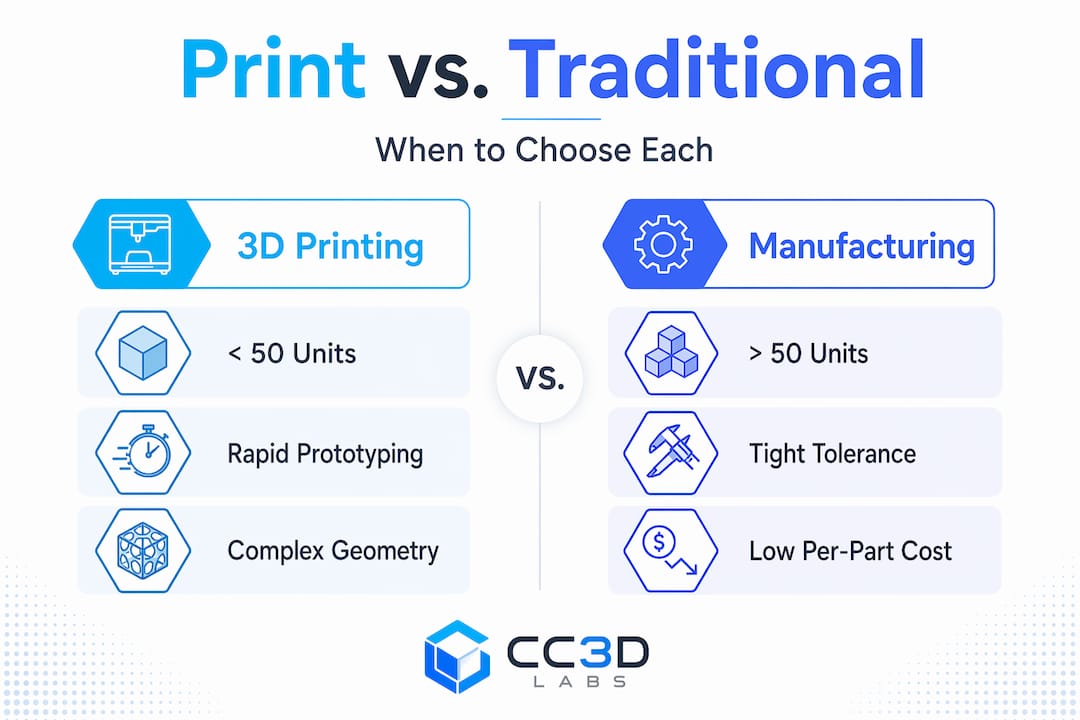
Know your volume breakpoint 3D printing is cost-effective under roughly 50 units; beyond that, CNC or injection molding typically wins on economics.
Document every iteration Consistent parameter records let you reproduce a successful print and diagnose failures without guessing.

Your functional parts printing guide starts with design

Most print failures are decided before the first layer is deposited. The design stage is where functional parts are won or lost, and the engineers who understand that produce better parts faster than those who treat design-for-additive as an afterthought.

Start with a clear mechanical requirements brief. List the expected loads, operating temperature range, required tolerances, and assembly interfaces. Then map failure modes. A housing that must survive drop impacts has entirely different geometry requirements than a fluid-flow test fixture. Functional prototyping methods must match the validation need, and that alignment begins with understanding what a failed test actually tells you.

Layer orientation drives strength more than material choice does. Layer orientation in additive manufacturing critically impacts anisotropic strength and must be planned around principal loading directions. An FDM part loaded perpendicular to its layer lines will fail at a fraction of the load it could handle if printed with layers running parallel to the stress. Model this in your CAD setup before slicing.

Key design principles for functional parts:

  • Replace sharp internal corners with fillets of at least 0.5mm to reduce stress concentration and improve layer-to-layer adhesion at transitions
  • Keep minimum wall thickness above 1.2mm for FDM and 0.8mm for SLA to avoid fragile shell sections
  • Align critical interfaces, such as press-fit bores and threaded inserts, with the print’s strongest axis
  • Use integrated functional features like living hinges and printed bearings rather than designing parts that require complex post-assembly
  • Apply DFM principles from concept: applying DFM early accelerates timelines by 25 to 60 percent and can yield up to 40 percent cost savings

Pro Tip: Maintain separate CAD versions for your printed prototype and any future machined or cast production version. The geometric requirements conflict enough that a single model leads to compromises in both.

Step-by-step process for printing functional prototypes

Once your design is optimized, the printing workflow itself has to be deliberate. Skipping validation steps at any stage compounds errors and wastes print time.

  1. Validate the mesh file. Run your STL or 3MF file through a mesh repair tool before slicing. Check for non-manifold edges, inverted normals, and wall thickness violations. A five-minute file check prevents a ten-hour failed print.
  2. Select the right printing technology. FDM works well for structural iteration in engineering thermoplastics like PETG, ASA, or Nylon. SLA delivers tighter dimensional accuracy for fluid interfaces and fine geometry. SLS produces isotropic parts without support structures, which matters for complex functional geometries. For prototypes under 50 units, additive manufacturing eliminates tooling costs entirely and can deliver small polymer parts in 4 to 12 hours. Refer to the right printing type guide when choosing between technologies for a specific functional requirement.
  3. Set parameters for strength, not speed. Increase infill to at least 40 percent for load-bearing parts. Use rectilinear or gyroid infill patterns over grid, which stress concentrates at nodes. Reduce print speed by 20 to 30 percent for the perimeter walls where surface finish directly affects friction fits and sealing faces.
  4. Optimize support placement. Overhang angles beyond 45 degrees require support, but support removal always risks surface damage. Reorient parts to minimize support contact on functional surfaces. Where support is unavoidable, use soluble support material or a low interface density.
  5. Iterate with intention. Track each parameter change against a specific performance hypothesis. 3D printing enables multiple design cycles in the time that one CNC prototype would require, but only if each cycle tests a defined variable.

Pro Tip: For Nylon and other hygroscopic materials, dry filament in an oven at 65°C for four hours before printing. Moisture in the filament creates porosity that destroys inter-layer adhesion in functional parts.

Read the filament prototyping guide for a deeper breakdown of material-specific settings and how they affect mechanical output.

Post-processing and quality control for functional parts

Printing is not the last step. Post-processing for 3D printed parts — including cleaning, surface finishing, and inspection — is vital to ensuring functional performance and repeatability. Incomplete post-processing can directly undermine mechanical properties.

The specific workflow depends on your printing technology:

  • FDM parts: Remove support structures carefully using flush cutters and files. Sand critical mating surfaces with 220 to 400 grit sandpaper, progressing through grits to avoid micro-scratches that act as crack initiation points. Apply thin layers of cyanoacrylate to sealing surfaces for improved surface density.
  • SLA parts: Wash in isopropyl alcohol immediately after printing to remove uncured resin. Post-cure under UV light to complete the polymer crosslinking; under-cured SLA parts are brittle and will test poorly. Measure cure time against the resin manufacturer’s specification, not by appearance.
  • SLS parts: Media blast to remove powder and improve surface finish. The naturally porous surface benefits from infiltration with epoxy or urethane when the part must seal against fluid or gas.

Dimensional inspection is where many teams cut corners and pay for it later. Use calipers for general tolerances, but for critical interfaces, use a coordinate measuring approach to verify feature locations against your CAD nominal. Document every inspection result alongside the print parameters. This record becomes the foundation for process repeatability when you need to reproduce a successful part weeks later.

Pro Tip: If a functional part shows warping or delamination, do not simply reprint. First diagnose the root cause — bed adhesion, cooling rate, or material moisture — or you will repeat the failure.

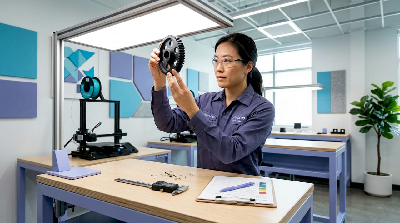
Technician checks 3D printed part for defects

Choosing between printing and traditional manufacturing

Understanding where additive manufacturing fits in your product lifecycle prevents misallocated budget and inconclusive test results. The manufacturing method must align with what you are trying to prove at each project stage.

Infographic comparing 3D printing and manufacturing use cases

Stage Best method Reason
Concept validation FDM / SLA Fast geometry confirmation, low cost, accepts frequent changes
Functional prototype testing SLS / SLA / FDM with engineering resins Isotropic properties or tight tolerances for credible mechanical data
Bridge production (under 50 units) SLS or metal printing No tooling investment, delivery in days
Low-to-mid volume (50 to 500 units) CNC machining Tight tolerances, consistent material properties, lower unit cost
High volume (500+ units) Injection molding Lowest unit cost, highest repeatability

3D printing becomes cost-prohibitive for runs beyond low-volume production. At that point, injection molding and CNC machining reduce unit costs substantially. The mistake many teams make is staying with 3D printing past the point where it makes economic sense, or switching to machining before the design has stabilized, which forces expensive tooling changes.

Hybrid workflows solve much of this problem. Print the structural prototype, machine the critical mating surfaces to tolerance after printing, and validate the combination. This approach captures the speed of additive and the precision of subtractive manufacturing without fully committing to either until the design is frozen. The manufacturing-grade 3D printing guide covers the specific parameter requirements when parts need to meet production-level standards.

Many engineers also underestimate how much mismatching prototyping methods to validation goals costs in wasted test cycles. A printed part that behaves differently from the production material under load does not invalidate the design. It invalidates the test.

My take on functional printing after years in the field

I’ve watched engineers with genuinely strong mechanical instincts make avoidable mistakes with additive manufacturing, and nearly all of them stem from the same place: treating 3D printing as a faster version of machining rather than as its own discipline.

The anisotropy issue alone has cost teams weeks. I’ve seen a structurally sound bracket design fail at 30 percent of its calculated load simply because nobody modeled the print orientation against the load direction. The fix took ten minutes in the slicer. The realization cost three weeks of iteration.

What I’ve found is that upfront process discipline, which means designing for the print, not the part, pays back faster than any other investment in a project. Teams that document their parameter decisions from iteration one spend half the time troubleshooting as those who treat each print as a fresh experiment.

My strongest recommendation: adopt hybrid manufacturing thinking from day one. Don’t wait until you hit a production volume to start thinking about how your additive prototype relates to your machined or molded production part. The design choices you make for printability will often conflict with the choices that make a part manufacturable at scale. Knowing that early changes the conversation and keeps the project on schedule.

Speed is seductive in prototyping. But a well-planned slower iteration beats three fast ones that tell you nothing.

— Justin

How Cc3dlabs can support your functional parts projects

https://cc3dlabs.com

Cc3dlabs, based near Philadelphia, works directly with engineers and product developers on exactly this kind of challenge: functional parts that have to perform, not just exist. Their professional 3D printing services cover FDM with engineering-grade filaments, multi-color printing, CAD support, and professional handheld 3D scanning (accuracy to ~0.1 mm) for post-print inspection. Whether you need a single functional prototype or a low-volume production run of 30 parts, Cc3dlabs offers free online estimates, design feedback, and fast local turnaround with international shipping. If your team needs a reliable partner to take a validated design from prototype through bridge production, reach out to Cc3dlabs for a project consultation.

FAQ

What materials work best for functional 3D printed parts?

PETG, Nylon, ASA, and PEEK are the most widely used engineering filaments for functional FDM parts, selected based on temperature resistance, chemical exposure, and mechanical load requirements. For SLA, engineering resins rated for ABS-like or high-temp behavior outperform standard resins in functional testing.

How does print orientation affect part strength?

Layer orientation controls the direction of anisotropy in printed parts, meaning a part loaded perpendicular to its layer lines will fail significantly earlier than one printed with layers parallel to the principal stress. Always orient parts so critical load paths run along the layer direction, not across it.

When should I switch from 3D printing to CNC machining?

3D printing is cost-effective for prototypes and small batches under roughly 50 units. Beyond that threshold, or when tolerances tighter than ±0.1mm are required across multiple features, CNC machining delivers better economics and more reliable dimensional accuracy.

What causes warping in functional parts and how do I fix it?

Warping results from differential thermal contraction during cooling, most commonly in large, flat FDM parts printed in ABS or Nylon. Fix it by using a heated enclosure, increasing bed temperature, adding a brim, and drying filament thoroughly before printing.

How do I verify that a printed functional part meets my design specifications?

Use calipers for general dimension checks and a coordinate measuring device or 3D scan for critical feature verification. Document each inspection result against the print parameters so you can reproduce passing parts and trace the cause of any out-of-tolerance results.