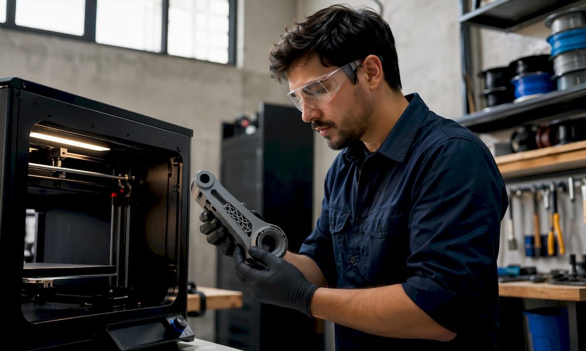
Technician removing 3D printed robot arm part

Building Custom Robot Parts With 3D Printing


TL;DR:

  • Additive manufacturing allows rapid creation of functional robot components directly from digital files. It enables customization of geometry and material, making prototyping faster and more accessible for small teams and individual developers. Proper design, material choice, and calibration are essential for producing durable, reliable robotic parts.

Additive manufacturing for robotics is defined as the process of producing functional mechanical components layer by layer from digital files, and it is the fastest way to go from concept to working prototype. Building custom robot parts with 3D printing gives engineers direct control over geometry, material, and iteration speed that traditional machining cannot match. A fully functional robotic arm can be built for around $220 in materials using standard servos and a desktop FDM printer. That cost point makes serious robotics prototyping accessible to individual developers and small teams for the first time.
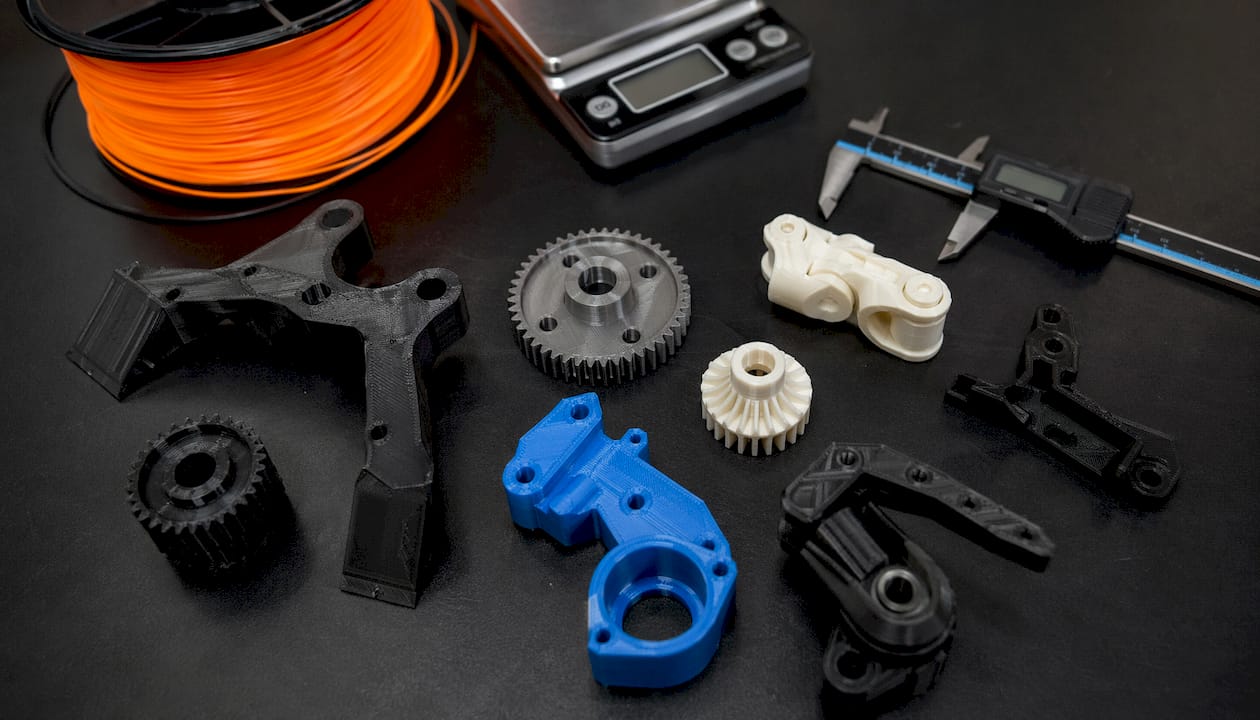
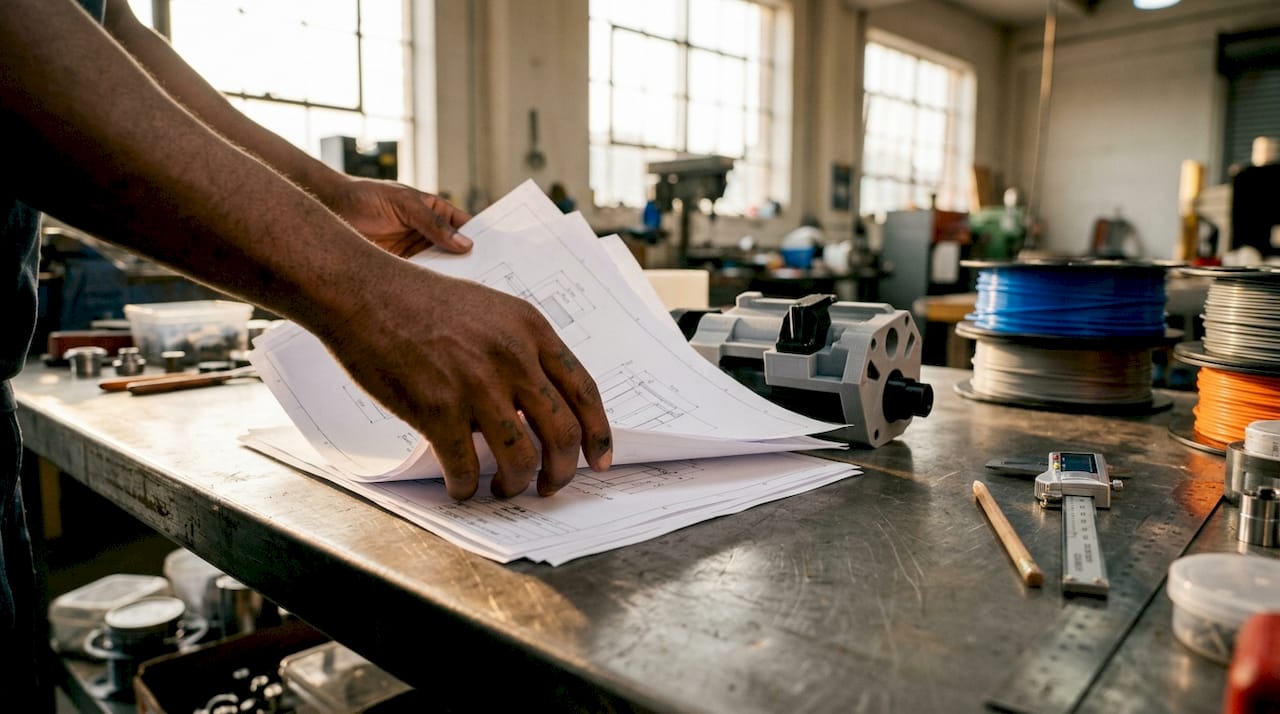
Detailed 3D printed robot parts on workshop table

What do you need to start building custom robot parts with 3D printing?

The right equipment determines whether your printed parts are functional or frustrating. Three printer technologies cover most robotics applications: FDM, SLA, and SLS. Each has a distinct role.

FDM printing offers fast, low-cost prototyping with visible layer lines and anisotropic strength. That means the part is stronger along the X and Y axes than along the Z axis. SLA produces high-resolution parts with smooth surfaces, which is useful for small linkages and sensor housings. SLS delivers isotropic strength and complex geometry without support structures, but at a significantly higher cost per part. For most product developers starting out, FDM is the correct first choice.

Choosing the right filament

Material selection is the single biggest variable in part performance. The table below summarizes the four filaments engineers use most often for 3D printed robot components.

Filament Strength Heat resistance Best use
PLA Moderate Low (~60°C) Prototypes, non-load-bearing frames
PETG Good Medium (~80°C) Structural brackets, enclosures
ABS Good High (~100°C) Housings, gears, functional parts
Carbon fiber reinforced High High Load-bearing arms, structural links

Carbon and glass fiber reinforced filaments provide higher stiffness and heat resistance but require careful print parameter tuning to avoid delamination. For a deeper breakdown of how these materials compare in real applications, the PLA vs. PETG vs. ABS guide from Cc3dlabs covers the tradeoffs in detail.
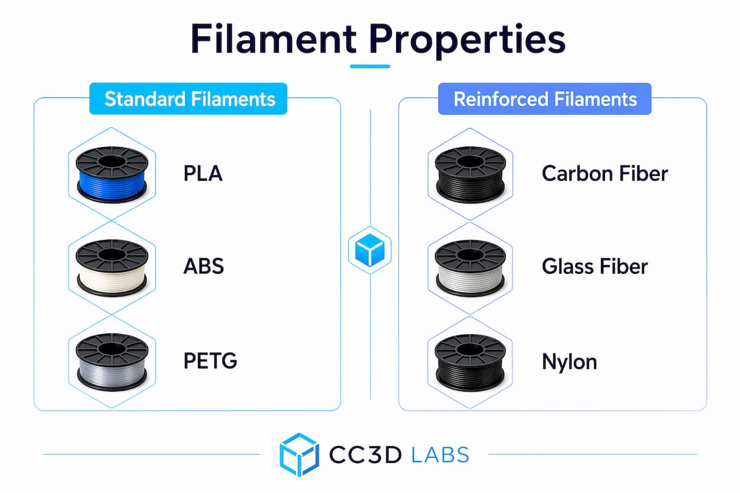
Infographic comparing standard vs reinforced filaments

Software and hardware essentials

CAD software such as Fusion 360, SolidWorks, or FreeCAD handles part geometry. A slicer like PrusaSlicer or Bambu Studio converts the model into printer instructions. Beyond the printer, you need servo motors, M3/M4 fasteners, heat-set brass inserts, and a soldering iron for electronics integration.

How do you design robot parts for strength and function?

Good robot parts design starts with two principles: modularity and load path awareness. Both directly affect how long your parts last and how fast you can fix them when they fail.

Modular robot design with replaceable sub-assemblies improves maintenance speed and iteration rate compared to monolithic designs. When a joint bracket breaks, you reprint that one piece instead of rebuilding the entire arm. This approach also lets you test different geometries for a single joint without redesigning the whole robot.

Selecting infill patterns, wall perimeters of 3 or more, and correct print orientation is critical for structural integrity in functional printed parts. Novice designers consistently underestimate anisotropic stresses, which causes premature part failure under load. Orient parts so the primary load runs parallel to the print layers, not perpendicular to them. For infill, gyroid and honeycomb patterns distribute stress more evenly than rectilinear in parts that experience multi-directional loading. The 3D print infill guide from Cc3dlabs explains pattern selection with specific strength data.

Tolerances and calibration

Dimensional accuracy determines whether your assembly fits together or binds. Print a calibration cube before committing to a full part run. Measure the result with calipers and apply a scaling correction in your slicer or CAD file. For press-fit joints, start with 0.1–0.2mm clearance and adjust based on your printer’s actual output. Calibration prints and measured offsets in CAD or the slicer correct dimensional inaccuracies before they become assembly problems.

Pro Tip: Design cable routing channels and mounting bosses directly into your printed parts. Integrated wiring channels reduce clutter, protect wires from mechanical wear, and make the assembly far easier to service.

What is the step-by-step process for printing and assembling robot parts?

Execution follows a clear sequence. Skipping steps, especially in post-processing, is the most common reason functional parts fail in the field.

  1. Prepare your CAD file. Export as STL or 3MF. Check for non-manifold geometry using Meshmixer or your slicer’s repair tool.
  2. Set slicing parameters. Use 3+ wall perimeters, 30–40% infill for structural parts, and orient the part for maximum load-path alignment.
  3. Print structural components. Enable supports only where geometry requires them. Unnecessary supports add removal time and can damage surface finish.
  4. Remove supports and post-process. Clean support interfaces with flush cutters and needle-nose pliers. For PETG and ABS, annealing and surface treatment relieve internal stresses and improve fatigue resistance.
  5. Install heat-set inserts. Use a soldering iron set to the filament’s softening temperature. Press inserts in straight to avoid angled threads.
  6. Mount servos and electronics. Secure servos with M3 screws into the heat-set inserts. Route wiring through the printed channels before closing any covers.
  7. Test under load before final assembly. Run the joint through its full range of motion with the servo powered. Listen for binding and check for flex in the bracket.

The table below summarizes each phase with realistic time estimates for a single robotic arm joint.

Phase Key action Estimated time
File prep CAD export, repair, slicer setup 30–60 minutes
Printing Structural parts at standard quality 2–6 hours
Post-processing Support removal, annealing, sanding 30–90 minutes
Hardware integration Inserts, servos, wiring 45–90 minutes
Testing Load test, fit check, iteration 30–60 minutes

Pro Tip: Print a single test joint before committing to a full arm print. A 20-minute test part catches fit and clearance problems that would otherwise waste hours of print time.

How do you troubleshoot common issues with 3D-printed robot parts?

Most print and assembly failures have a known cause and a direct fix. The key is diagnosing the right layer of the problem.

  • Warping: Caused by thermal contraction during cooling. Fix with a heated bed, enclosure, or brim. ABS requires an enclosure; PETG rarely warps on a heated glass bed.
  • Under-extrusion: Produces weak, porous layers. Check for a partial clog, reduce print speed by 20%, and verify your extruder steps-per-millimeter calibration.
  • Layer delamination: Usually caused by printing too fast or at too low a temperature. Increase nozzle temperature by 5°C increments until layers bond properly.
  • Dimensional inaccuracy: Parts that are consistently oversized or undersized need a flow rate or XY scaling correction in the slicer. Measure a calibration cube and apply the offset.
  • Stripped heat-set inserts: Caused by under-sized holes or inserts installed at an angle. Redesign the boss with a 0.1mm larger bore and reinstall with a straight press.
  • Joint flex or failure: Increase wall count to 4–5 perimeters, switch to a stiffer filament, or reorient the part so the load runs along the print layers.

For modular designs, the repair strategy is straightforward. Identify the failed sub-assembly, reprint only that component, and swap it in. This is the core advantage of modular design for maintenance. Keeping a small stock of commonly stressed parts, such as wrist brackets and servo mounts, eliminates downtime during testing cycles.

One often-overlooked failure mode is fatigue from vibration. Parts that pass a static load test can still crack after repeated motion cycles. Test every joint through at least 500 full cycles before declaring a design production-ready. If you are working with high-speed or high-load applications, carbon fiber part failure modes are worth understanding before you commit to reinforced filaments.

Key Takeaways

Building custom robot parts with 3D printing requires material selection, design optimization for anisotropic strength, and a modular assembly approach to produce reliable, maintainable robotic components.

Point Details
Material choice drives performance Match filament to load and heat requirements; use PETG or ABS for structural parts.
Print orientation is structural Orient parts so primary loads run parallel to print layers to avoid anisotropic failure.
Modular design speeds iteration Build robots as collections of replaceable sub-assemblies to cut repair and testing time.
Post-processing matters Annealing and surface treatment improve fatigue resistance and dimensional accuracy.
Calibrate before full production Run calibration prints and apply measured offsets before printing final functional parts.

What I’ve learned from printing robot parts that textbooks skip

The biggest mistake I see engineers make is treating 3D printing as a direct substitute for machined metal. It is not. It is a different manufacturing method with its own failure modes, and the ones that catch people off guard are almost always orientation-related. A bracket that looks overbuilt on screen can split cleanly along a layer line under a load that machined aluminum would shrug off. The fix is not always more material. Often it is just a 90-degree rotation in the slicer.

The second lesson is that modular design is not just a maintenance convenience. It is a prototyping accelerator. When you build a robot as a collection of discrete, replaceable joints and brackets, you can run parallel experiments. Print three versions of a wrist joint with different wall counts, test them simultaneously, and have a winner in a day. Monolithic designs force you to reprint the whole assembly every time you change one variable.

My honest recommendation for anyone starting out: spend more time on your first calibration print than you think you need to. Measure every face of the calibration cube, apply the corrections, and print it again. The 45 minutes you invest there will save you hours of failed assemblies later. The functional parts printing guide from Cc3dlabs covers this calibration workflow in depth and is worth reading before your first structural print.

— Justin

Cc3dlabs can print your custom robot parts with precision

Cc3dlabs is a professional 3D printing service based near Philadelphia, specializing in filament-based printing for functional parts, prototypes, and batch production. Engineers and product developers use Cc3dlabs when they need parts that meet tight tolerances without the overhead of running their own print farm.

https://cc3dlabs.com

The team at Cc3dlabs handles everything from CAD modeling and design support to multi-color printing and post-processing. Turnaround times are fast, and the service scales from a single prototype to production-volume orders. Whether you need a one-off joint bracket or a full set of custom robotic components, Cc3dlabs delivers parts ready for assembly. Request a free online estimate directly on the website and get a quote without a sales call.

FAQ

What is the cheapest way to build a 3D-printed robot arm?

A fully 3D-printed robotic arm costs approximately $220 in materials using standard servos and a desktop FDM printer, excluding the printer itself. PLA or PETG filament keeps per-part costs low while still delivering adequate strength for light-duty applications.

Which filament is best for structural robot parts?

PETG is the best starting point for structural 3D printed robot components because it balances strength, heat resistance, and printability. Carbon fiber reinforced filaments offer higher stiffness for demanding applications but require careful print settings to avoid delamination.

How do I make 3D-printed robot parts stronger?

Use 3 or more wall perimeters, orient parts so the primary load runs parallel to the print layers, and choose an infill pattern like gyroid or honeycomb for multi-directional stress. Post-processing with annealing further improves fatigue resistance.

What CAD software works best for robot parts design?

Fusion 360 and SolidWorks are the most widely used CAD tools for custom 3D parts for robotics because both support parametric modeling and direct STL export. FreeCAD is a capable free alternative for engineers on a tight budget.

How tight should tolerances be for 3D-printed robot joints?

Start with 0.1–0.2mm clearance for moving joints and adjust based on calibration prints measured with calipers. Applying a scaling correction in your slicer before printing final parts prevents fit problems during assembly.

Woman typing custom 3D print quote request email

Getting a Quote for Custom 3D Print: Full Guide


TL;DR:

  • Getting a 3D print quote requires a clean CAD file, clear project details, and understanding the cost factors involved. Accurate quotes depend on proper file formats, specified materials, quantities, and end-use information, with larger batch sizes lowering per-unit costs. Comparing quotes effectively involves confirming identical parameters and requesting detailed breakdowns to avoid surprises.

Getting a quote for custom 3D printing means submitting your CAD files and project details so a provider can calculate costs based on material, machine time, and post-processing requirements. The industry term for this process is a “print estimate request,” though most clients simply call it requesting a custom 3D print quote. Accurate quotes depend entirely on the quality of information you provide upfront. Providers like Cc3dlabs review file geometry, material suitability, and batch size before confirming any price. This guide covers what to prepare, how to submit your request, what drives pricing, and how to compare quotes with confidence.

What do you need to prepare before getting a quote for custom 3D print?

The single most important step before requesting a quote is preparing a proper 3D CAD file. Accurate quotes require CAD formats like STL, STEP, or 3MF with clean, watertight geometry. A 2D drawing or a photo gives a provider zero volume or geometry data to price from. If your file has open surfaces, inverted normals, or non-manifold edges, expect delays or a request to resubmit.

Beyond the file itself, you need to define your project parameters clearly before you reach out. Here is what to gather:

  • Material type and grade. Specify whether you need PLA, PETG, ABS, ASA, TPU, or an engineering-grade filament. Each carries a different cost and performance profile.
  • Color and finish. Note your target color and whether you need a raw print, light sanding, priming, or a painted finish.
  • Quantity and batch size. State your exact quantity. Pricing changes significantly at volume thresholds.
  • Functional requirements. Describe the end use. A bracket that holds 50 lbs needs different material and infill than a display model.
  • Tolerances and fit. If the part mates with another component, specify the clearance or tolerance class.
  • Deadline and delivery. Include your hard deadline and whether local pickup or shipping applies.

Pro Tip: Send a dimensioned drawing or reference image alongside your CAD file. It gives the reviewer context that geometry alone cannot communicate, especially for parts with critical mating surfaces.

Clarifying end-use application at the quoting stage is critical to selecting the correct materials and quality controls. Skipping this step leads to reprints, cost overruns, and missed deadlines.

Hands arranging 3D print files and prototype on table

How do you request a custom 3D print quote step by step?

Submitting a quote request is straightforward when you follow a clear sequence. Skipping steps creates back-and-forth that delays your estimate by days.

  1. Upload your 3D file. Use the provider’s online form or email. Cc3dlabs accepts STL, STEP, and 3MF files through its online quote request form. Compress multiple files into a single ZIP archive to avoid attachment issues.
  2. Select your material and technology. Choose the filament type and, if relevant, the print technology. Filament-based FDM is the most common and cost-effective option for functional parts and prototypes.
  3. Specify quantity tiers. Do not request a price for one quantity only. Ask for pricing at two or three volume levels so you can plan economically.
  4. Add post-processing instructions. State whether you need support removal only, sanding, priming, or a specific surface treatment. Providers price these separately.
  5. Note any special requirements. Include color matching references, insert hardware needs, or assembly requirements.
  6. Confirm your deadline. State whether your timeline is flexible or fixed. Rush orders carry a price premium.
  7. Wait for manual review. Most professional providers follow up with questions before confirming a final price. This is normal and necessary.

Pro Tip: Request pricing for 10, 50, and 200 units in the same submission. Batch pricing tiers reveal economies of scale that can shift your production strategy entirely.

One critical distinction: an instant online estimate and a confirmed professional quote are not the same thing. Final professional quotes often come in above automated calculator outputs because manual review catches wall thickness issues, support complexity, and failure risk that algorithms miss. Treat any instant number as a rough budget figure, not a binding price.

What factors drive custom 3D print pricing?

Custom 3D print pricing is not a single line item. It is a sum of several distinct cost components, each of which you can influence with better project planning.

Infographic showing factors influencing custom 3D print pricing

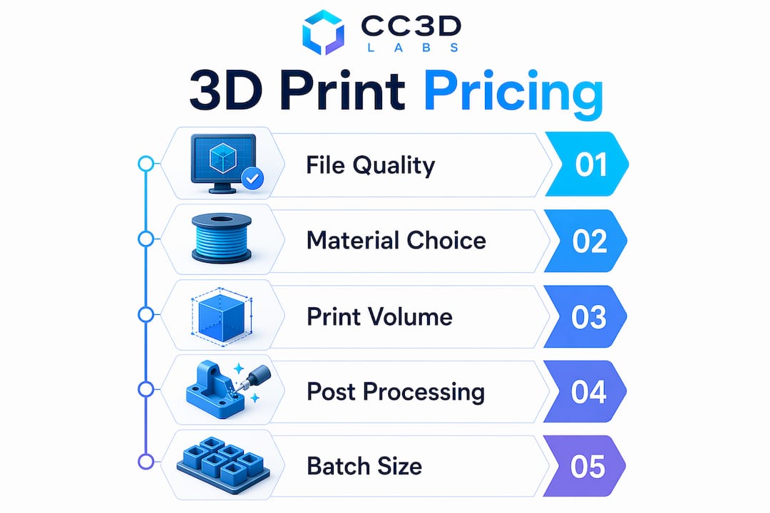
Pricing includes material volume, machine time, support burden, post-processing labor, and packaging. That last point surprises most first-time buyers. A small, geometrically complex part can cost more than a large simple block because it demands more machine time and cleanup labor.

Here are the primary cost drivers:

  • Material volume and type. Denser, engineering-grade filaments cost more per gram. High-infill settings increase material consumption directly.
  • Machine time. Print speed, layer height, and part orientation all affect how long the printer runs. Longer print times mean higher costs.
  • Support structures. Overhanging geometry requires support material that must be removed and disposed of. Heavy support burden adds both material and labor cost.
  • Post-processing. Sanding, priming, painting, and hardware insertion are billed separately. A raw print is always cheaper than a finished one.
  • Setup and quality control. Some commercial services set minimum order values to cover base operational overhead; CC 3D Labs quotes each job individually. This covers file review, machine setup, and inspection.
  • Rush orders. Expedited orders increase pricing substantially because they compress scheduling and raise the cost of any failure.
Cost factor What drives it up How to reduce it
Material volume High infill, dense filament Optimize infill for function, not maximum strength
Machine time Complex geometry, fine layer height Simplify geometry where tolerances allow
Support burden Steep overhangs, internal cavities Reorient the part or redesign to minimize overhangs
Post-processing Painted or primed finish Accept raw finish for non-visible or functional parts
Rush premium Short lead time Plan orders at least two weeks ahead

Batch size is the most powerful lever most buyers underuse. Many providers discount larger batches because setup and handling overhead spreads across more parts — at CC 3D Labs, volume pricing is quoted per project after a test print of your actual part. If your project allows any flexibility on quantity, run the numbers at multiple tiers before committing.

How do you compare, negotiate, and validate 3D printing quotes?

Comparing quotes from different providers is only useful when all quotes describe the same job. One quote that includes support removal and another that excludes it are not comparable, even if the headline numbers look similar.

“Clients often treat a quote request as a single price check instead of a planning tool. Requesting pricing across multiple quantity bands, 10, 50, and 200 units, gives you a real picture of your project economics and often reveals a tipping point where a larger order pays for itself.”

Follow these practices to compare and validate quotes with confidence:

  • Confirm all parameters match. Verify that material, quantity, finish level, and lead time are identical across every quote you receive.
  • Ask what is excluded. Shipping, packaging, and quality inspection are sometimes listed separately. A low headline price can carry significant add-ons.
  • Request a breakdown. A credible provider will itemize material, machine time, post-processing, and overhead. Vague lump-sum quotes are a red flag.
  • Ask about revision handling. If the first print has a defect, what is the policy? Reprints, credits, and refunds vary widely by provider.
  • Verify lead time is realistic. A quote with an aggressive delivery date that the provider cannot guarantee creates project risk, not savings.
  • Plan for approval time. Factor in your own internal review and approval cycle when evaluating whether a quoted lead time actually works.

Machine time and support burden are primary cost drivers. A provider who explains these factors in their quote breakdown is demonstrating transparency. One who cannot explain why a small part costs more than a large one is not a reliable partner for complex projects.

You can also reduce your own costs before the quote stage. Reviewing your 3D printing cost strategies before submitting files often reveals geometry changes that cut machine time without affecting part function.

Key Takeaways

Getting a precise custom 3D print quote requires clean CAD files, clear project specifications, and an understanding of the cost components that providers use to build their pricing.

Point Details
File format is non-negotiable Submit STL, STEP, or 3MF files with watertight geometry; photos and 2D drawings cannot be priced.
Instant estimates are not final quotes Automated calculators frequently underestimate the confirmed professional quote due to missed geometry risks.
Batch size drives per-unit cost Larger batches usually bring per-unit cost down as setup overhead spreads across the run.
Rush orders carry a real premium Expedited timelines increase pricing due to compressed scheduling and higher failure risk.
Compare quotes on identical parameters Confirm material, finish, quantity, and lead time match before treating any two quotes as comparable.

What I’ve learned from watching buyers misread quotes

Most pricing surprises I’ve seen come from one source: buyers treating the first number they receive as the final number. An instant calculator gives you a floor, not a ceiling. The manual review that follows almost always adds cost because it catches what the algorithm missed, wall thickness violations, unsupported overhangs, and geometry that will fail mid-print.

The second most common mistake is submitting a quote request for a single quantity. I’ve watched product developers lock into a 10-unit order, receive the quote, and then discover that 50 units would have cost only 30% more in total. That math changes a sourcing decision entirely. Always ask for pricing across at least two or three quantity bands before you commit.

The detail that most buyers skip is the end-use description. Telling a provider “I need this printed in plastic” is not useful. Telling them “this bracket mounts inside an engine bay and sees 90°C continuous heat” tells them to quote ASA or a high-temperature filament instead of PLA. That single sentence prevents a failed part and a reprint cost. If you want on-demand custom parts that actually perform in their intended environment, the spec sheet you send in is the most important document in the process.

— Justin

Cc3dlabs makes precise custom 3D print quotes straightforward

Cc3dlabs handles quote requests for prototypes, functional parts, and batch production runs from its facility near Philadelphia.

https://cc3dlabs.com

Submit your STL, STEP, or 3MF file through the Cc3dlabs 3D printing services page and receive a detailed estimate that covers material, machine time, post-processing, and shipping. The team reviews every file for printability before confirming a price, so the number you receive reflects the actual job, not an automated approximation. Cc3dlabs supports multi-color printing, engineering-grade filaments, and batch pricing with volume discounts. Rush orders and design support are available on request. Local pickup near Philadelphia and domestic or international shipping are both options.

FAQ

What file format do I need to get a 3D print quote?

STL, STEP, and 3MF are the standard formats accepted by professional 3D print services. The file must have clean, watertight geometry; 2D drawings and photos cannot be used for pricing.

Why is my final quote higher than the instant online estimate?

Final professional quotes are often higher than instant calculator outputs because manual review identifies wall thickness issues, support complexity, and failure risk that automated tools miss.

How does quantity affect custom 3D print pricing?

Larger quantities reduce per-unit cost through tiered discounts. Volume discounts vary widely by provider and part — at CC 3D Labs, batch pricing is quoted per project after a test print.

What information should I include in a quote request?

Include your 3D file, material preference, required quantity, finish level, end-use description, tolerances, and your deadline. The more detail you provide, the more accurate and faster your quote will be.

Is there a minimum order for custom 3D printing services?

Some professional services set minimum order values to cover machine setup, file review, and quality inspection overhead; CC 3D Labs quotes each job individually. Check the provider’s terms before submitting a small single-unit request.

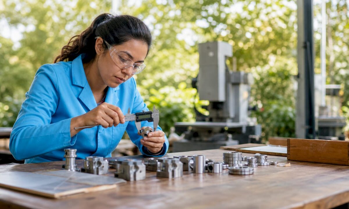
Engineer measuring custom batch components

What Is Custom Batch Manufacturing? A Clear Guide


TL;DR:

  • Custom batch manufacturing produces tailored products in defined groups with planned quality checks and changeovers. It offers flexibility, traceability, and precision for moderate-volume runs, serving industries like aerospace and medical devices. Proper design and process management optimize costs and ensure high-quality results for each batch produced.

Custom batch manufacturing is the production of tailored products in defined groups, or batches, under consistent conditions, with planned pauses between runs for quality checks and changeover. The industry term for the broader category is batch production, and the custom variant adds a layer of specification: every batch is built to a client’s exact requirements. This method occupies the middle ground between job shop production and continuous manufacturing, making it the go-to choice for manufacturers who need more than one-off parts but far fewer than mass-production volumes. Cc3dlabs works within this model daily, producing precise filament-based parts in defined runs for product developers, businesses, and designers.

What is custom batch manufacturing, exactly?

Custom batch manufacturing is defined as producing a specified quantity of customized products in a single production run, then stopping before the next batch begins. That pause is not downtime. It is a deliberate checkpoint for cleaning, recalibration, and quality verification. Batch manufacturing sits between job shop production, which handles one-off or very low-volume work, and continuous manufacturing, which never stops. The custom element means each batch is built to a client’s specifications, not a generic catalog standard.

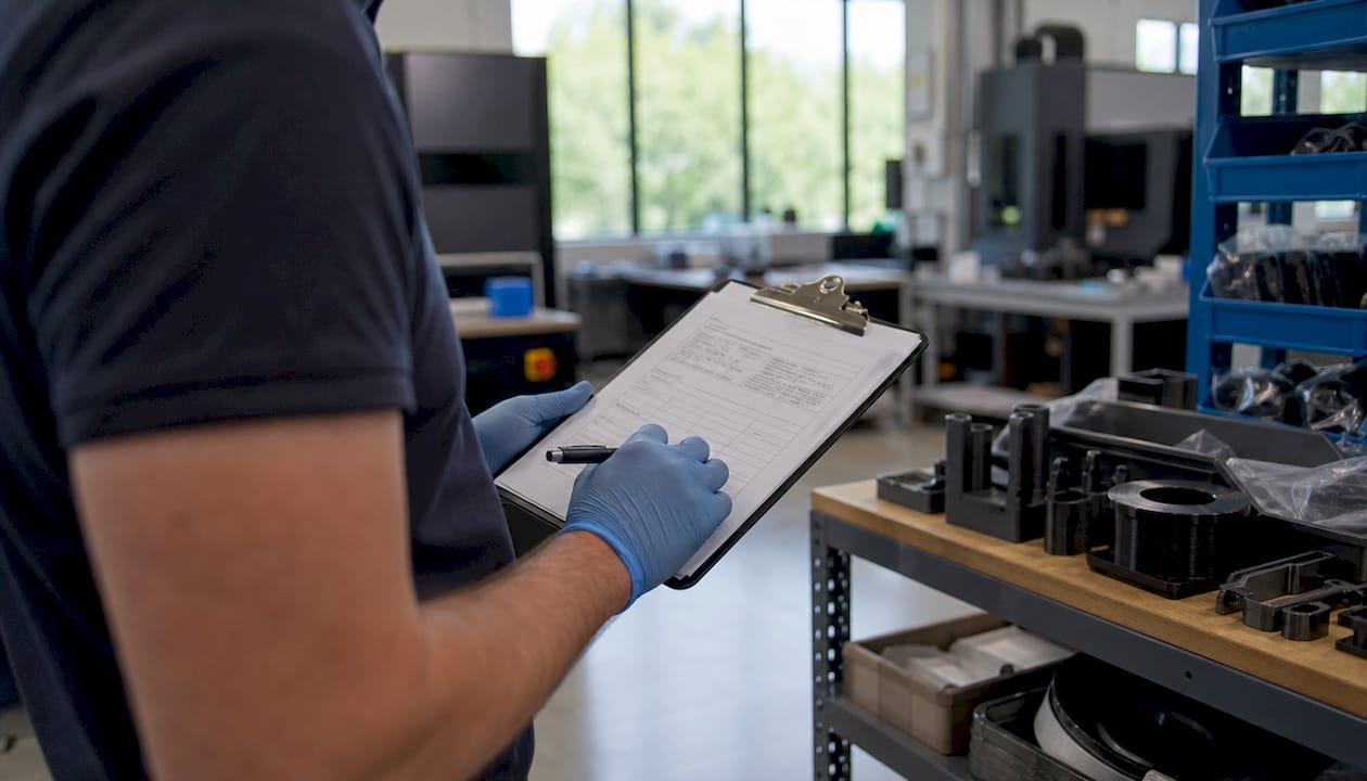
Technician reviewing batch production documentation

The stop-and-start rhythm is what separates batch production from a continuous flow line. A pharmaceutical company producing a specific drug formulation, a food manufacturer running a seasonal recipe, or a product developer ordering 50 functional prototypes all use this model. Each batch gets its own identity, its own quality record, and its own set of parameters. That structure is what makes the method both flexible and traceable.

Pro Tip: Treat each batch as a discrete project with its own documentation file. This habit pays off immediately when a quality issue surfaces and you need to isolate the affected run without pulling the entire production history.

How does the custom manufacturing process work?

The custom manufacturing process follows six defined stages, and skipping any one of them is where most costly errors originate.

  1. Define specifications. The client and manufacturer agree on materials, tolerances, quantities, and functional requirements before any design work begins.
  2. CAD design and validation. Engineers translate requirements into a 3D model. This stage includes Design for Manufacturability (DFM) review, which checks whether the design can be produced efficiently with the chosen method.
  3. Select the manufacturing method. Options include additive manufacturing such as filament-based 3D printing, CNC machining, injection molding, or a combination. The choice depends on volume, material, and tolerance requirements.
  4. Quote and finalize specs. The manufacturer confirms lead times, costs, and any design adjustments identified during DFM review.
  5. In-process quality control. Inspections happen during the run, not only at the end. Measurements, visual checks, and functional tests are logged against the batch record.
  6. Final assembly and delivery. Finished parts are inspected against the original specification, packaged, and shipped or made available for local pickup.

Successful custom manufacturing depends on a close working relationship between the designer and the manufacturer. High communication levels prevent costly errors and keep the production aligned with the original intent. A designer who understands machining constraints, and a manufacturer who understands the product’s end use, produce better results than either party working in isolation.

Pro Tip: Request a DFM report before approving your final design. A good manufacturer will flag features that add cost without adding function, such as unnecessary undercuts or overly tight tolerances on non-critical surfaces.

How does custom batch compare to job shop and mass production?

Understanding where custom batch manufacturing fits requires a clear look at the three main production paradigms. Each one trades off volume, flexibility, and cost differently.

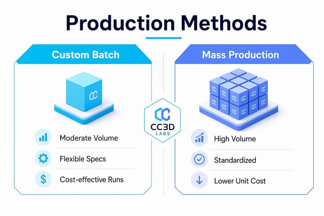
Infographic comparing custom batch and mass production

Batch production suits moderate-volume runs where product formulas or configurations vary between batches. Job shop production handles very low volumes with maximum customization, often one part at a time. Mass production runs the same product continuously at high volume with minimal variation.

Production type Typical volume Flexibility Per-unit cost Best use case
Job shop Very low (1–10 units) Very high Very high One-off prototypes, bespoke parts
Custom batch Low to moderate (10–5,000 units) High Moderate Specialized products, regulated industries
Standard batch Moderate (1,000–50,000 units) Moderate Lower Consumer goods, food, pharma
Mass production Very high (50,000+ units) Low Lowest Commodity products, automotive

Custom batch manufacturing spans a wide tolerance range depending on process: precision CNC machining can hold roughly ±0.005–0.02 mm, while FDM additive manufacturing typically holds ±0.2–0.5 mm — ample for most functional parts. That level of precision is not available in standard mass production without significant tooling investment. The trade-off is a higher per-unit cost, which is justified when the product requires exact specifications or regulatory traceability.

The key distinction between custom batch and standard batch is the degree of specification per run. Standard batch production uses a fixed formula repeated across many runs. Custom batch production adjusts parameters, materials, or configurations for each client order. That adjustment is where the value lives for product developers and niche manufacturers.

What are the advantages and applications of custom batch manufacturing?

Custom batch manufacturing delivers three core advantages: flexibility, traceability, and quality control. Each one matters more in some industries than others, but all three apply across the board.

Flexibility means a manufacturer can shift from producing a medical device housing to an aerospace bracket between runs without retooling an entire production line. Batch production enables rapid market response with less financial risk than mass production. A business can test a new product with a run of 200 units, gather real-world feedback, and adjust the design before committing to larger volumes.

Traceability is the feature that regulated industries cannot operate without. Batch manufacturing tracks each production run uniquely, which is critical in pharmaceuticals, food production, and medical device manufacturing. If a defect surfaces, the investigation targets one batch, not the entire production history. That focused scope minimizes recall costs and regulatory exposure.

Quality control benefits from the stop-and-start structure. Each pause between batches is an opportunity to verify that the process is still within specification before committing more material and labor to the next run.

“Batch records are vital quality control tools that allow targeted investigations and minimize production impact during defects. Documentation supports traceability and audits across regulated industries.”

— Unleashed Software, Batch Production Explained

The industries that rely most heavily on custom batch manufacturing include aerospace, medical devices, specialty food and pharma formulations, and niche consumer products. An aerospace supplier producing a run of 50 custom brackets needs documented traceability for each part. A medical device company producing a limited run of surgical guides needs both precision and a complete quality record. Custom batch manufacturing serves both requirements in a single workflow. The same principle applies in brake manufacturing quality control, where batch traceability directly affects safety outcomes.

What practical tips help optimize custom batch workflows?

Setup time is the biggest cost driver in low-volume custom batch manufacturing. DFM practices reduce repositioning during machining and cut idle machine time, which directly lowers labor costs per part. A design that requires five fixture changes costs more to produce than one requiring two, even if the material cost is identical.

The following practices consistently reduce cost and delay in custom batch production:

  • Plan changeover time explicitly. Ignoring changeover time causes unexpected timeline extensions. Build cleaning, recalibration, and setup into the project schedule from day one, not as an afterthought.
  • Maintain batch records throughout the run. Documentation is not a post-production task. Logging measurements and process parameters during the run gives you real-time data to catch drift before it becomes a defect.
  • Choose the right technology for the volume. Additive manufacturing, including low-volume 3D printing, suits runs where tooling cost would make CNC or injection molding uneconomical. CNC machining suits runs where tight tolerances and material strength are non-negotiable.
  • Standardize your incoming material checks. Batch failures often trace back to material variation, not process variation. A quick incoming inspection prevents a bad material lot from contaminating an entire run.
  • Communicate design changes in writing. Verbal changes between batches are where errors enter. A written change order tied to the batch record keeps the production history clean and auditable.

Pro Tip: Ask your manufacturer to run a first-article inspection on the initial unit of each new batch. Catching a dimensional error on part one costs far less than discovering it on part forty.

Key Takeaways

Custom batch manufacturing is the most practical production method for manufacturers and designers who need precision, traceability, and flexibility without the volume commitments of mass production.

Point Details
Core definition Custom batch manufacturing produces tailored products in defined runs with planned pauses for quality control and changeover.
Six-stage workflow Every run moves from spec definition through CAD, method selection, quoting, in-process QC, and final delivery.
Traceability advantage Each batch carries a unique record, enabling targeted investigations and minimizing recall scope in regulated industries.
DFM reduces cost Design for Manufacturability review cuts setup complexity and idle machine time before production begins.
Technology fit matters Additive manufacturing suits low-volume custom runs; CNC machining suits high-precision, moderate-volume requirements.

Why custom batch manufacturing is underrated as a product launch strategy

Most product developers I work with arrive thinking they need to choose between a one-off prototype and a full production run. That binary thinking leaves a lot of value on the table. Custom batch manufacturing is the tool that lets you do neither and both at once.

A run of 50 to 500 units gives you real-world data, actual customer feedback, and a documented production process you can hand to a larger manufacturer later. The batch record you build during that first run becomes your quality baseline. Every subsequent run either confirms that baseline or tells you something changed. That is not just manufacturing discipline. It is product intelligence.

The integration of CAD modeling workflows with flexible production lines has made custom batch manufacturing more accessible than it was a decade ago. Digital design files move directly into production without the tooling delays that once made small runs expensive. Entrepreneurs who understand this can test and launch products faster than competitors still waiting for minimum order quantities from traditional suppliers.

The collaborative nature of custom batch work is also undervalued. A manufacturer who reviews your design before production starts is not just a vendor. That review catches problems that would otherwise show up as scrap, rework, or a failed product launch. The best custom batch relationships I have seen treat that DFM conversation as the most important meeting in the project.

— Justin

Cc3dlabs: precision 3D printing for custom batch production

Cc3dlabs, based near Philadelphia, specializes in filament-based custom 3D printing services built for exactly the kind of low-volume, high-specification runs that define custom batch manufacturing. Whether you need 10 functional prototypes or 500 production-grade parts, Cc3dlabs handles the full workflow from CAD review through final quality inspection.

https://cc3dlabs.com

The team at Cc3dlabs brings CAD modeling expertise and in-process quality control to every batch, so your parts arrive documented and verified. Multi-color printing, professional handheld 3D scanning (accuracy to ~0.1 mm), and design support are all available in a single service relationship. Get a free online estimate and see how a custom batch run can move your product from concept to verified production faster than traditional manufacturing routes.

FAQ

What is custom batch manufacturing in simple terms?

Custom batch manufacturing is the production of a specific quantity of tailored products in a single run, with planned stops between batches for quality checks and changeover. It sits between one-off job shop work and high-volume continuous production.

How does batch production differ from mass production?

Batch production runs defined quantities with pauses for recalibration and quality control, while mass production runs continuously at high volume with minimal variation. Batch production offers more flexibility and traceability at a higher per-unit cost.

What industries use custom batch manufacturing most?

Aerospace, medical devices, pharmaceuticals, specialty food production, and niche consumer products rely most heavily on custom batch manufacturing because they require both precision and documented traceability for each production run.

Why is DFM important in custom batch manufacturing?

Design for Manufacturability review reduces setup complexity and repositioning during machining, which directly lowers labor and machine idle costs. Running DFM before production starts is the single most effective way to reduce per-part cost in a custom batch run.

What is a batch record and why does it matter?

A batch record is a documented log of all process parameters, measurements, and quality checks for a single production run. It enables targeted investigations if a defect surfaces and supports regulatory audits without disrupting other production batches.

Designer sketching prototype goals at drafting table

How to Create Custom Prototypes: A Practical Guide


TL;DR:

  • Custom prototyping involves creating targeted models to test specific design assumptions before full production. It emphasizes selecting appropriate fidelity, materials, and tools to answer focused questions efficiently. Rapid iteration and early testing help identify issues and protect intellectual property effectively.

Custom prototyping is the process of building a targeted physical or digital model to test a specific design assumption before committing to full production. The industry term for this practice is rapid prototyping, and it covers everything from paper sketches to full CAD-driven 3D prints. Knowing how to create custom prototypes well means choosing the right fidelity, the right materials, and the right testing method for each stage of development. Tools like Figma, Fusion 360, and FDM 3D printers each serve different stages of the process. This guide walks you through every step, from goal definition to final iteration.

How to plan your custom prototype: defining goals and choosing tools

The single most important step in custom prototype design is defining one clear, testable question before you build anything. Defining a single testable question focuses the effort and improves the quality of feedback you collect. Examples include: can users complete a checkout flow without guidance, or does a layout surface the most critical information first?

Once you have that question, set explicit success criteria. Decide in advance what a passing result looks like. Without that benchmark, feedback becomes noise.

Protect your idea before you build. Securing IP protection via a provisional patent and documented creation dates is advisable before investing significant time and money in prototypes. Work with an IP attorney early, not after your design is already in someone else’s hands.

Tool selection follows goal definition. The table below maps common prototyping tools to their best use cases:

Tool Best for Fidelity Cost
Paper sketches Early concept exploration Low Minimal
Figma Digital UI and UX flows Low to medium Low
Fusion 360 / SolidWorks CAD modeling for physical parts High Medium to high
FDM 3D printing Functional physical prototypes Medium to high Medium
SLA / resin printing High-detail visual models High Medium to high
Foam / cardboard Form and ergonomics testing Low Minimal

Pro Tip: Start with the cheapest tool that can answer your question. If a cardboard mockup can validate the shape, do not spend three days in CAD first.

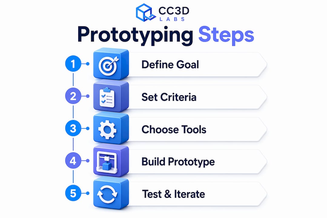
Infographic showing prototyping step-by-step guide

What are the common types of prototypes and when to use them?

Prototype types fall into four main categories, each suited to a different stage of development. Choosing the wrong type wastes time and produces misleading feedback.

  • Lo-fi (paper or digital wireframes). Best for early-stage concept validation. Rough sketches and Figma wireframes let you test layout and flow without building anything physical. Rough prototypes reduce distraction from surface polish and accelerate honest feedback from users. The downside is that they cannot validate physical fit, material feel, or mechanical function.

  • Looks-like prototypes. These focus on aesthetics and form without delivering full function. A resin-printed shell with no working electronics is a looks-like prototype. Use them for investor presentations, ergonomic reviews, and packaging fit checks. They are fast to produce but tell you nothing about whether the product actually works.

  • Works-like prototypes. These prove mechanical or software function without matching the final appearance. A breadboard circuit in a foam housing is a classic example. Use them to validate engineering assumptions and stress-test core mechanisms before spending money on cosmetics.

  • Combined works-like-looks-like prototypes. These integrate both form and function. They are expensive and time-consuming, so reserve them for late-stage validation before tooling or manufacturing investment.

  • Pre-production prototypes. Built to production specifications, these are used for final regulatory testing, manufacturing trials, and investor sign-off. They represent the highest cost and fidelity in the prototyping sequence.

The key rule: match prototype type to the specific risk you are testing at that moment. Do not build a pre-production prototype to answer a question a paper sketch could resolve in an afternoon.

Step-by-step guide to building and testing your custom prototype

A structured workflow separates developers who ship products from those who stay stuck in endless revision cycles. Iterative prototyping outperforms linear models because each cycle answers one question and feeds directly into the next build.

Follow these steps for creating effective prototypes:

  1. Sketch the concept. Draw the core idea by hand or in Figma. Focus only on the elements that relate to your testable question. Skip details that do not affect the outcome.

  2. Build the minimum viable prototype. Digital prototyping follows a path of research, sketching, interactive creation, testing, and refining. For physical builds, move from sketch to CAD model in Fusion 360 or SolidWorks. Keep geometry simple at this stage.

  3. Run a design for manufacturability (DFM) check. Before printing, review wall thickness, overhangs, and tolerances. This step prevents failed prints and wasted material.

  4. Print or fabricate. 3D printed prototypes are built via CAD modeling, DFM checks, print setup, and post-processing specific to the technology used. Print times range from 2 to 24 hours depending on part size and technology. FDM works for functional tests; SLA delivers finer surface detail for visual reviews.

  5. Post-process the part. Sand, prime, or paint as needed. For FDM prints, support removal and light sanding are standard. For SLA, UV curing is required after printing.

  6. Test with real users. Use moderated testing when you need to understand why users behave a certain way. Use unmoderated testing when you need behavioral data at scale. Frequent small validation cycles outperform one large test late in the process.

  7. Document findings and iterate. Record what worked, what failed, and what the next testable question is. Then repeat the cycle.

Pro Tip: Set a hard time limit on each build window, such as two days maximum per iteration. A constrained timeline forces you to prioritize the one feature that answers your question rather than adding scope.

A typical early-stage physical prototype cycle runs two to five days from sketch to tested part. Digital UI prototypes in Figma can complete a full cycle in under 24 hours. The faster your cycle, the more you learn before committing to expensive tooling.

How to choose materials and methods for custom prototypes

Material and method selection directly determines what questions your prototype can answer. The wrong combination produces data that does not transfer to the final product.

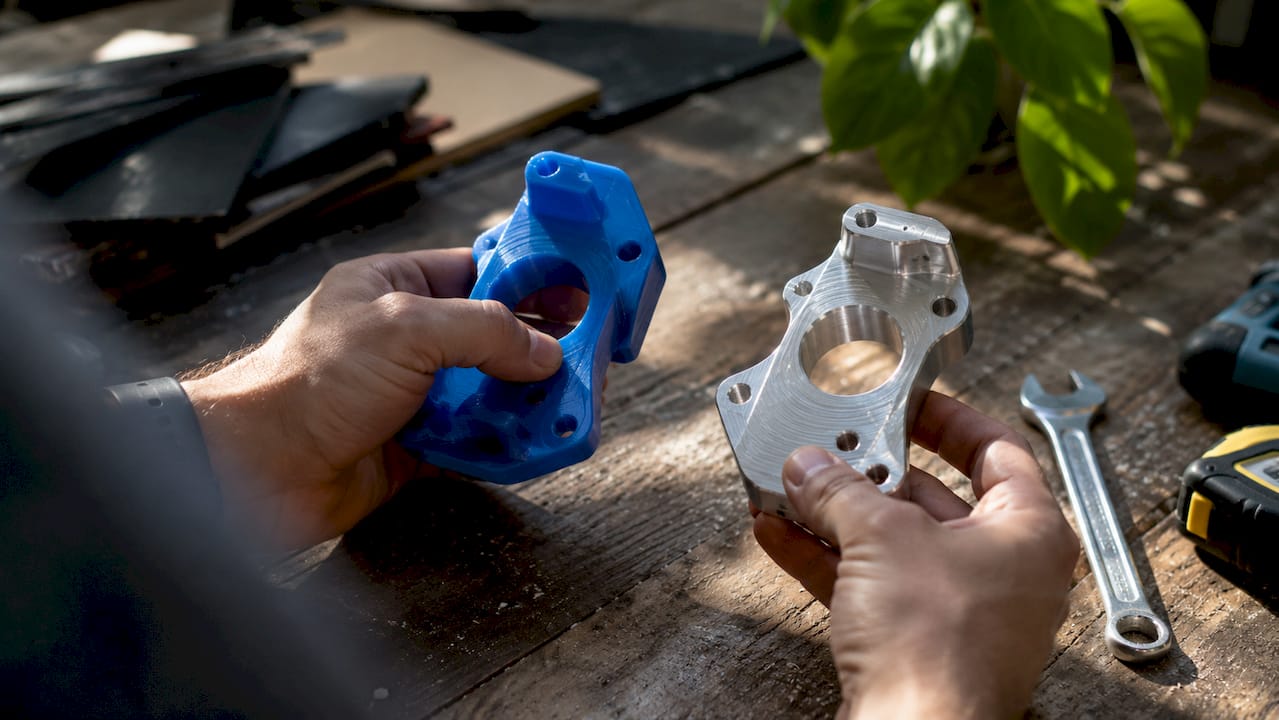
Hands comparing prototype materials in workshop

Method Material options Speed Detail level Relative cost
FDM 3D printing PLA, ABS, PETG, TPU Fast Medium Low
SLA / resin printing Standard, tough, flexible resins Medium High Medium
SLS 3D printing Nylon, glass-filled nylon Medium High High
CNC machining Aluminum, acetal, HDPE Slow Very high High
Handcrafting / foam Foam, cardboard, silicone Very fast Low Minimal
Silicone molding Silicone, urethane Medium High Medium

FDM printing with PLA or PETG is the fastest and most affordable path for functional fit-and-form testing. SLA resin printing produces finer surface detail, making it the right choice for consumer product aesthetics reviews. SLS nylon parts offer the best mechanical properties among 3D printing methods, which makes them suitable for load-bearing functional tests.

CNC machining delivers the tightest tolerances and is the correct choice when you need metal parts or production-equivalent material behavior. The tradeoff is cost and lead time. For early-stage work, CNC is rarely justified.

Choosing the right 3D printing type depends on the prototype’s purpose, required surface finish, and mechanical demands. A consumer electronics housing needs SLA for its surface quality. A bracket that must survive load testing needs SLS or CNC.

Pro Tip: Test material behavior separately from geometry. Print a small coupon of your chosen material and stress it before committing to a full prototype build. This saves hours of reprinting.

What common pitfalls should you avoid when creating custom prototypes?

Most prototyping failures share the same root cause: building too much before testing anything. Constraining features prevents prototype sprawl and the delays that come with it.

  • Skipping goal definition. Building without a testable question produces a prototype that looks impressive but answers nothing. Every build must trace back to a specific risk or assumption.

  • Starting at high fidelity too early. A polished prototype signals to users that the design is finished. That perception suppresses honest feedback. Low-fidelity early prototypes enable more honest and actionable user feedback by removing the distraction of surface polish.

  • Testing too late and too rarely. One large test at the end of a development phase is the most expensive way to find problems. Small, frequent tests catch issues while they are still cheap to fix.

  • Ignoring what users actually do. Developers often watch users struggle with a prototype and instinctively explain the interface rather than observing. Let users fail. Their confusion is the data.

  • Neglecting IP protection. Sharing a prototype with manufacturers or investors before filing a provisional patent exposes your design to risk. Document creation dates and consult an IP attorney before any external sharing.

“Prototyping creates options for product development by testing single moments of value quickly and iteratively, maximizing learning speed and leverage.”

Scope creep is the silent killer of prototype cycles. Every feature you add beyond the testable question extends your build time and dilutes your results. Treat each prototype as a focused experiment, not a product preview.

Key Takeaways

Effective custom prototyping requires a defined question, the right fidelity for each stage, and short iterative cycles that build knowledge faster than any single large test.

Point Details
Define one testable question Every prototype must answer a specific risk before you build anything.
Match fidelity to the stage Use lo-fi sketches early; reserve high-fidelity builds for late-stage validation.
Choose materials by purpose FDM suits functional tests; SLA suits visual reviews; SLS suits load-bearing parts.
Test early and often Frequent small cycles outperform one large test late in the process.
Protect IP before sharing File a provisional patent and document creation dates before external exposure.

What I’ve learned from years of watching prototypes succeed and fail

The most common mistake I see from product developers is treating the first prototype as a draft of the final product. It is not. It is a question written in physical form. The moment you start adding features that are not tied to your testable question, you have stopped prototyping and started building. Those are very different activities.

The second lesson is that material choice reveals things CAD cannot. I have watched engineers spend weeks perfecting a model in Fusion 360, only to discover that the chosen material flexes in a way the simulation never predicted. A two-hour coupon test with the actual filament or resin would have caught that on day one. Physical behavior is not fully predictable from a screen.

Collaboration across disciplines also changes prototype outcomes in ways that are hard to overstate. When a mechanical engineer, a UX designer, and a manufacturing specialist review the same prototype together, they catch three different categories of problems in a single session. Siloed review misses the intersections where real product failures live.

My honest recommendation for anyone new to iterative prototyping: start with the lowest fidelity that can answer your question, set a hard deadline on the build, and get it in front of a real user within 48 hours. Speed of learning beats quality of prototype at every early stage.

— Justin

Cc3dlabs can help you build your next prototype faster

Physical prototyping moves faster when you have reliable print quality and material options behind you. CC 3D Labs, based near Philadelphia, offers custom 3D printing services covering FDM and multi-color (AMS) printing for prototypes, functional parts, and batch production runs.

https://cc3dlabs.com

Whether you need a single concept model or a series of iterated parts, Cc3dlabs provides CAD support, design for manufacturability review, and fast turnaround with local pickup or shipping. Their team works with product developers and engineers who need accurate, durable parts without long lead times. If you want to see how 3D printing drives product innovation at every stage of development, Cc3dlabs is a direct path from CAD file to tested physical prototype.

FAQ

What is a custom prototype in product development?

A custom prototype is a targeted model built to test a specific design assumption or risk before full production. It can be physical, digital, or a combination of both, depending on what question it needs to answer.

How long does it take to build a custom prototype?

Physical 3D printed prototypes typically take 2–24 hours to print, plus additional time for post-processing and testing. Digital prototypes in tools like Figma can complete a full build-and-test cycle in under 24 hours.

What materials work best for physical prototypes?

FDM materials like PLA and PETG work best for functional fit tests. SLA resin delivers finer surface detail for visual reviews. SLS nylon is the strongest option for load-bearing functional prototypes.

Should I protect my IP before prototyping?

Filing a provisional patent and documenting creation dates before sharing your prototype with any external party is the standard recommendation. Consult an IP attorney before showing your design to manufacturers or investors.

What is the difference between a works-like and a looks-like prototype?

A works-like prototype validates mechanical or software function without matching the final appearance. A looks-like prototype matches the final form and aesthetics without delivering working function. Each type answers a different category of design risk.