
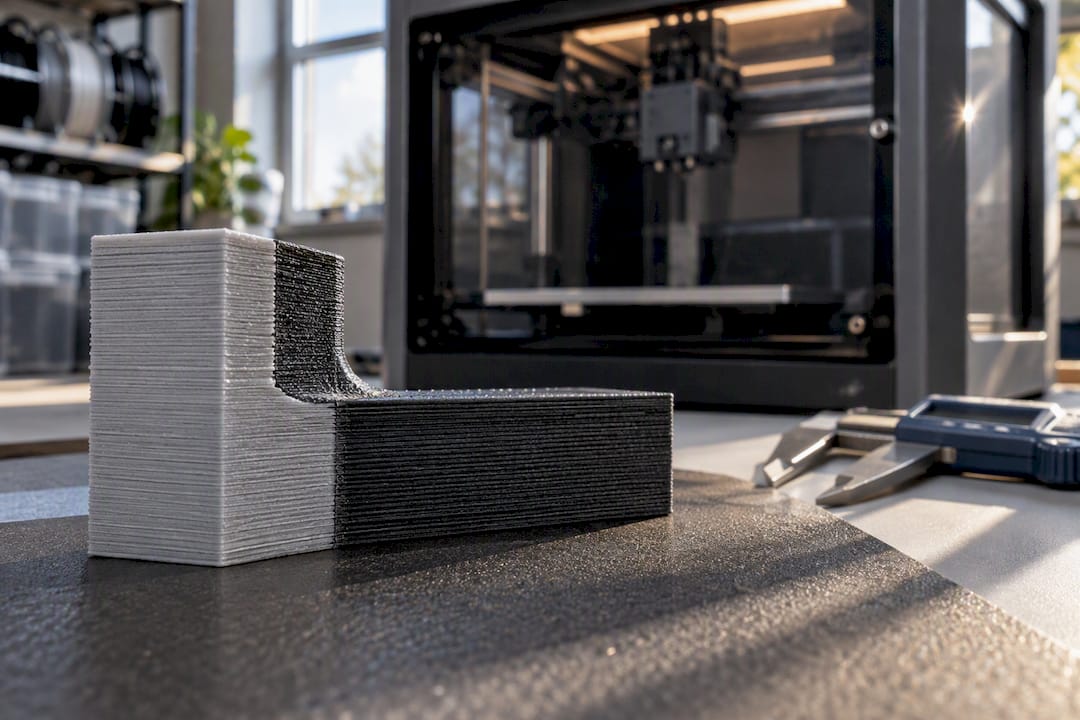
Multi material FDM is the practice of depositing two or more distinct filaments within a single print, using architectures ranging from filament managers and single nozzle purge systems to IDEX, tool changers, and coextrusion heads. Every one of these approaches faces the same limiting factor: interfacial adhesion between dissimilar materials and positional repeatability at the nozzle. Get those two variables wrong and the mechanical properties of the part collapse at the seam, regardless of how capable the hardware is.
TL;DR:
- Achieving strong interfacial adhesion in multimaterial FDM depends on precise nozzle calibration, matching thermal windows, and controlling extrusion volume at interfaces.
- Filament management systems trade speed for material variety, while IDEX setups require strict head-to-head repeatability to minimize waste and improve bond quality.
- Designing for multimaterial assembly should prioritize mechanical interlocks and gradual transitions to reduce stress concentrations and prevent delamination.
- Small calibration errors in nozzle offset or extrusion multiplier significantly weaken bonds and can cause warping or interface failure, requiring careful process control.
- Complex printhead innovations like nozzle arrays and coextruders enable graded compositions or higher throughput but increase hardware complexity and control demands.
Table of Contents
- Architecture families: how multimaterial FDM systems are built and their trade-offs
- Material compatibility and interfacial adhesion: experimental findings and practical implications
- DfAM and geometry tactics for multimaterial parts
- Calibration and process parameters that materially change interface quality
- Nozzle and feed innovations: coextrusion, static mixers, nozzle arrays, and production implications
- Production and workflow considerations: purge waste, filament buffers, and when to scale
- Post-processing techniques specific to multi-material prints
- Common failure modes unique to multi-material FDM prints
- Applications and industry use-cases illustrating the benefits and challenges of multi-material FDM
- Recent advances and research trends in multi-material FDM technology
- CC 3D Labs perspective: when to hire a specialist and what we handle
- How to get a quote and next steps with CC 3D Labs
- Sources
- FAQ
Architecture families: how multimaterial FDM systems are built and their trade-offs
Filament managers sit outside the toolhead and feed different materials into a shared path, relying on a filament buffer to absorb the speed mismatch between the assist motor and the extruder. Single nozzle purge systems solve material switching by pushing the old filament out through a waste tower before loading the next one, which keeps the mechanism simple but wastes material and risks contamination at the tip if purging is incomplete.
IDEX systems mount two independent extruders on separate carriages, cutting purge waste dramatically because each material has its own nozzle, but that benefit only holds if the X, Y, and Z offsets between the two heads are calibrated precisely. Multi nozzle tool changers swap physical toolheads between materials, and coextrusion designs blend filaments before deposition, both trading simplicity for throughput and added software complexity.
- Filament managers favor material variety over speed and need reliable buffering to avoid feed stalls.
- Single nozzle purge systems are mechanically simple but generate the most waste and contamination risk.
- IDEX systems cut purge volume sharply but demand tight head-to-head repeatability.
- Tool changers and coextruders raise throughput and material flexibility at the cost of calibration complexity.
Material compatibility and interfacial adhesion: experimental findings and practical implications
Interfacial strength in multimaterial parts depends on diffusion across the boundary, mechanical interlocking from surface texture, and the brief thermal window during which the second material can bond before the interface cools past its softening point. Tensile testing on ABS-PLA specimens found that extrusion temperature and over extrusion levels significantly influence the strength of the resulting composite, and that nozzle position deviations as small as about 0.04 millimeters meaningfully reduced interfacial strength in process-dependent adhesion testing.
Nozzle distance functions as a practical proxy for extrusion volume at the interface: reducing nozzle distance by 5% of layer height produces an effect on local extrusion similar to raising the extrusion multiplier by roughly 5% in that same region, according to the process-dependent adhesion testing. That gives engineers a second calibration lever when temperature alone cannot close a weak seam.
Compatibility follows thermal processing windows more than chemical similarity alone. Materials with overlapping softening and glass transition ranges tend to fuse more readily, while pairs separated by a large thermal gap struggle to bond regardless of print settings.
- Favor material pairs with overlapping extrusion temperature ranges before attempting a new combination.
- Treat a wide gap in glass transition temperature as a warning sign, not a settings problem to fix later.
- Run a small tensile or peel test coupon for any untested pairing before committing to a full production part.
DfAM and geometry tactics for multimaterial parts
Design decisions made before slicing often matter more than any process tweak made after. Placing material interfaces away from high tensile load paths, or reinforcing them with mechanical interlocks such as dovetails or tongue-and-groove joints, keeps the weakest plane of the part out of the load path entirely. Gradual transitions, built through geometric tapering or infill density gradients, distribute stress across a wider zone instead of concentrating it at a single sharp boundary.
Support material choice depends on geometry access: soluble supports handle enclosed or inaccessible cavities but add material and post-processing cost, while breakaway supports suit accessible features and cut total production cost when paired with sound design-for-manufacturing tactics.
- Map every planned material interface against the part’s expected load paths.
- Add mechanical interlocks anywhere an interface crosses a high stress zone.
- Replace sharp material boundaries with tapered or gradient transitions where feasible.
- Choose soluble supports only where breakaway removal is not physically possible.
- Run a small test coupon of the actual material pairing before slicing the full model.
Pro Tip: Model the interface geometry as its own feature in CAD rather than letting the slicer decide where materials split, so you control exactly where the weak plane lands.
Calibration and process parameters that materially change interface quality
Nozzle offset accuracy is the single most consequential calibration step in any multi-head system, because very small deviations on the order of a few hundredths of a millimeter measurably weaken the bond. The process-dependent adhesion study found that nozzle position errors of this magnitude were enough to reduce interfacial strength, which sets a realistic tolerance target for XY and Z offset calibration on any dual-head or tool-changing setup.
Extrusion multiplier and nozzle distance work as linked controls at the interface: increasing local extrusion volume through either lever forces more material into contact across the boundary, improving mechanical interlock at the cost of slightly rougher surface finish nearby.
- Calibrate XY and Z offsets first, since positional error compounds every downstream adjustment.
- Raise extrusion multiplier or lower nozzle distance specifically at the interface layer, not across the whole part.
- Increase the second material’s extrusion temperature modestly to widen the bonding window without degrading the polymer.
- Print a small lap-joint or peel-test coupon in the actual material pair before running the production file.
Nozzle and feed innovations: coextrusion, static mixers, nozzle arrays, and production implications
Research into printhead design has produced four broad classes of innovation aimed at expanding what multimaterial FDM can do. A survey of these approaches found that nozzle arrays, coextruders, static mixers, and advective assemblers each trade capability for complexity in different ways: some enable functionally graded compositions, others focus on higher throughput, and a few are built specifically for fine-feature multimaterial interfaces.
- Nozzle arrays deposit multiple materials in parallel, raising throughput at the cost of resolution per material.
- Coextruders blend filaments before deposition, useful for graded compositions but demanding tighter thermal control.
- Static mixers homogenize material streams inline, trading fine interface control for consistency across a gradient.
- Advective assemblers manipulate flow patterns to create layered or graded microstructures within a single bead.
Pre-structured mixing at the printhead is a promising route for functionally graded parts, but it shifts complexity from the slicer into the printhead itself, which is worth the investment only when a project genuinely needs graded properties rather than discrete material zones.
Production and workflow considerations: purge waste, filament buffers, and when to scale
Purge volume is the recurring operational cost in multimaterial production, and mapping which materials print adjacent to each other in a job queue reduces the number of full purges needed per part. Filament buffers are not optional accessories in most multi-manager setups: feeding speeds between assist motors and the toolhead extruder rarely match exactly, and equipment connection guidance notes that buffers and splitters directly limit how many filament managers can be connected and how far color or material count can scale.
- Sequence material assignments to minimize the number of full purge cycles per job.
- Treat filament buffers as required infrastructure, not an afterthought, in any multi-unit setup.
- Watch accessory count (splitters, buffers, PTFE adapters) as the real ceiling on how far a setup scales.
Pro Tip: When purge waste, buffer failures, or interface rework start eating more time than the part itself is worth, that is the signal to move the job to a dedicated production workflow instead of your own bench.
Post-processing techniques specific to multi-material prints
Multimaterial parts often need finishing work that single-material prints do not. Sanding across a material boundary is riskier than on a homogeneous surface, since the two polymers can differ in hardness and remove at different rates, leaving a visible ridge instead of a smooth transition. Working the interface with progressively finer grits, and stopping short of aggressive sanding on the softer material, keeps the boundary visually even.
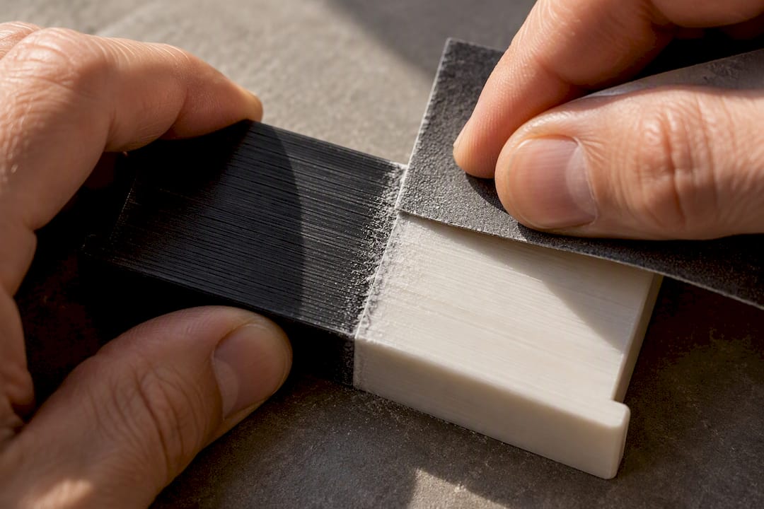
Solvent smoothing works well for some single materials but is generally a poor choice across a multimaterial seam, since a solvent tuned for one polymer can leave the other unaffected or, worse, degrade it. Mechanical finishing methods (sanding, light bead blasting) are the safer default when the two materials differ chemically.
Painting or dyeing across an interface benefits from a light mechanical key, such as fine sanding, applied evenly to both materials so the surface accepts a coating consistently rather than absorbing unevenly on one side. Where the interface itself is the visual feature, some practitioners intentionally leave a slight step or texture change rather than trying to disguise it entirely, since forcing a seamless blend across dissimilar polymers is harder to achieve reliably than designing the transition to read as intentional.
Vapor exposure and any thermal post-process should be tested on a scrap coupon of the exact material pair first, because uneven softening at different temperatures can distort one material before the other responds at all.
Common failure modes unique to multi-material FDM prints
Delamination at the material boundary is the most common failure, and it traces back almost every time to one of two causes: insufficient extrusion volume at the interface, or nozzle contamination carried over from a purge that did not fully clear the previous material. The process-dependent adhesion study identifies nozzle pollution as a primary root cause of interface failure, meaning periodic nozzle maintenance and deliberate purge-path planning are not optional housekeeping but core process controls.
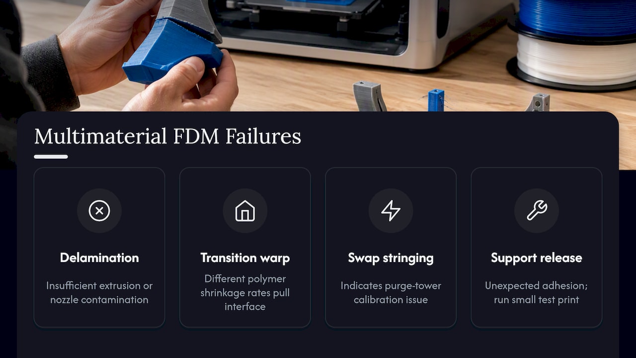
Warping at a material transition often shows up when two polymers with different shrinkage rates cool at different speeds, pulling the interface apart from the inside as the part cools on the bed. This is distinct from ordinary warping and usually needs a design fix (a mechanical interlock or gradient transition) rather than a slicer setting.
Stringing or blobbing localized to material swaps points to purge tower calibration rather than general retraction settings, since the transition itself is the variable changing, not the base filament behavior. Support material that will not release cleanly from the model, particularly with breakaway supports on a model material it was not tested against, reflects the counterintuitive adhesion patterns documented in the polymer adhesion investigation: dedicated support materials sometimes bond more weakly than model-to-model pairings, and some support-model combinations unexpectedly bond too well to remove cleanly. Both outcomes call for a small test print before committing a full support strategy to production.
Applications and industry use-cases illustrating the benefits and challenges of multi-material FDM
Multimaterial FDM earns its place where a single part needs properties that no single filament provides: a rigid structural body paired with a flexible seal, a load-bearing frame paired with a soft-touch grip, or a functional prototype that combines a support material with an engineering-grade model material to test fit and function together. Automotive restoration and reverse-engineering work benefit from this in a specific way, since a reproduced part can combine a stiff structural material with a lower-durometer gasket surface in one build rather than requiring separate parts assembled after printing.
Product development teams use multimaterial builds to test form and function in a single iteration instead of printing and assembling two separate parts, cutting the number of prototype cycles needed before a design is validated. Functionally graded material research, which varies composition gradually through a part rather than at a sharp boundary, remains largely at the research stage: a review of FFF methods for graded materials notes real promise for parts with spatially varying properties, but also that the approach still demands careful material proportioning and tight process control that most production shops are not yet set up to run routinely.
The common thread across every use case is the same trade-off covered throughout this guide: multimaterial builds solve real design problems that single-material parts cannot, but every added material interface is another place the part can fail if adhesion and calibration are not verified first.
Recent advances and research trends in multi-material FDM technology
Printhead research has moved from simply switching materials to actively shaping how they combine. The nozzle innovation survey referenced earlier groups current research into four distinct classes of nozzle design, several of which are aimed specifically at producing functionally graded compositions rather than discrete material zones, a capability that was largely out of reach for standard purge or IDEX systems.
Academic work on experimental multimaterial rigs continues to inform how commercial systems evolve. An open thesis on multi-material, multi-technology FDM systems documents custom hardware and testing frameworks built specifically to study process improvements, work that predates much of today’s commercial hardware but still underpins the calibration logic used in current adhesion research.
The clearest trend across recent studies is a shift toward measurement-based calibration rather than fixed settings copied from one machine to another. Because interfacial strength has been shown to respond to changes as small as fractions of a millimeter in nozzle position, research is increasingly framing multimaterial print quality as a function of per-machine calibration data rather than universal presets, a shift that pushes serious multimaterial work toward test coupons and documented process parameters rather than default profiles.
CC 3D Labs perspective: when to hire a specialist and what we handle
Multimaterial projects with tight interface requirements, functional testing needs, or reverse-engineered geometry are often better handled by a dedicated production setup than a single bench machine. CC 3D Labs runs a production farm of Bambu Lab FDM printers across materials including PLA, PETG, ABS, ASA, PC, and carbon-fiber nylon, with multi-color and multi-material printing available, plus professional handheld 3D scanning accurate to about 0.1 millimeters and CAD services for scan-to-CAD reverse engineering. When an interface keeps failing on a bench setup, or a part needs to be reverse-engineered from a physical original before it can even be modeled for multimaterial printing, that is usually the point where outsourcing saves more time than it costs.
— Justin
How to get a quote and next steps with CC 3D Labs
Every job is quoted individually after a test print of the actual model; details on materials and capabilities are available on the provider’s website.
We are based in the Greater Philadelphia area (Bucks County, PA), with residential pickup for local customers and shipping available anywhere in the United States. Review the full range of 3D printing and scanning services and request a 3D print quote to get a test print started.
Sources
- Process-Dependent Influences on Adhesion in Multi-Material Extrusion
- Nozzle innovations that improve capacity and capabilities of multimaterial additive manufacturing
- Development of a Multi-Material, Multi-Technology FDM System For Process Improvement Experimentation
FAQ
What is multi-material 3D printing?
Multi-material 3D printing deposits two or more distinct filaments within a single print job, using hardware such as filament managers, purge systems, IDEX heads, or tool changers. The main challenge is achieving a strong bond between the materials at their shared boundary, which depends heavily on calibration and material compatibility.
Which is better, FDM or SLA?
The two processes serve different goals: FDM builds parts from extruded thermoplastic filament and supports multimaterial combinations, while SLA cures liquid resin layer by layer and is generally not suited to combining dissimilar engineering thermoplastics in one print. For multimaterial functional parts using materials like PLA, PETG, ABS, or ASA, FDM is the applicable process.
Which 3D printer is the best for multi-material printing?
There is no single best system: the right architecture depends on the project, since filament managers suit material variety, IDEX systems reduce purge waste, and tool changers or coextruders suit higher throughput or graded compositions. Engineers typically choose based on how much purge waste, calibration effort, and software complexity a project can tolerate.
Is it worth buying a multicolor 3D printer?
A multicolor or multimaterial printer is worth the investment when a project genuinely needs different properties or colors within one part, such as a rigid body paired with a flexible seal. For a single complex or high-stakes multimaterial part, sending the job to a production service after a test print often avoids the calibration and purge-waste learning curve entirely.