
Many product developers assume rapid prototyping is just another term for 3D printing. While additive manufacturing plays a major role, rapid prototyping encompasses a broader range of fabrication techniques designed to accelerate product development cycles. This guide explains the diverse methods available, from layer-by-layer builds to precision machining, and shows you how to select the right approach for your iteration needs. You’ll learn which techniques deliver the accuracy, material properties, and turnaround times your projects demand.
Table of Contents
- Key takeaways
- What is rapid prototyping and how does it work?
- Key rapid prototyping methods: strengths, uses, and mechanics
- Challenges and expert nuances in rapid prototyping
- Applying rapid prototyping effectively in SMB manufacturing
- Explore advanced rapid prototyping services at CC 3D Labs
- Frequently asked questions
Key Takeaways
| Point | Details |
|---|---|
| Broader than 3D printing | Rapid prototyping encompasses additive, subtractive, casting, forming and hybrid methods to speed design iterations. |
| Multiple fabrication methods | Techniques range from layer by layer builds to precision machining to accelerate development. |
| Fast iteration cycles | Iteration cycles shrink from weeks to hours or days. |
| Hybrid strategies boost results | Combining methods improves accuracy and material properties. |
What is rapid prototyping and how does it work?
Rapid prototyping transforms digital designs into physical parts faster than traditional manufacturing methods allow. Engineers and product developers use these techniques to validate concepts, test functionality, and refine designs before committing to full production tooling. The speed advantage comes from eliminating the lengthy setup processes that conventional manufacturing requires.
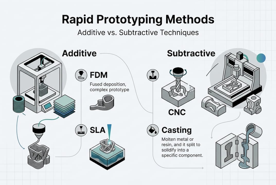
The technology landscape divides into three main categories. Additive manufacturing, commonly known as 3D printing, constructs parts by depositing material layer upon layer until the complete geometry emerges. Subtractive manufacturing takes the opposite approach, removing material from solid blocks through precision cutting and milling operations. Additional methods include casting, forming, and hybrid processes that combine multiple techniques.
On-demand 3D printing services have made additive methods accessible to businesses of all sizes. The process begins with a CAD model that defines every dimension and feature of the desired part. Software slices this model into thin cross-sections, generating instructions that guide the fabrication equipment. Each method interprets these instructions differently, whether curing liquid resin with lasers, fusing powder particles with heat, or extruding melted thermoplastic through precision nozzles.
The core principles remain consistent across technologies:
- Digital models eliminate physical tooling requirements
- Layer-based or stock-removal processes enable complex geometries
- Iteration cycles compress from weeks to hours or days
- Material waste decreases compared to traditional subtractive methods
- Design changes implement immediately without retooling costs
Manufacturers gain flexibility to explore multiple design variations simultaneously. A development team might produce five different handle geometries overnight, test them with users the next day, and refine the winning concept by week’s end. This velocity fundamentally changes how products evolve from initial sketches to market-ready solutions.
Key rapid prototyping methods: strengths, uses, and mechanics
Understanding the mechanical principles behind each fabrication method helps you match techniques to specific project requirements. Key methodologies include: SLA (high resolution, smooth finish), SLS/MJF (functional nylon parts, isotropic properties), FDM (fast iteration, early concepts), CNC (precision tolerances ±0.025-0.125mm, production materials). Each approach delivers distinct advantages for different prototyping scenarios.
Stereolithography (SLA) uses ultraviolet lasers to cure liquid photopolymer resin into solid cross-sections. The build platform lowers incrementally as each layer solidifies, producing parts with exceptional surface quality and fine feature resolution. Engineers choose SLA when visual appearance matters or when intricate details like small text, thin walls, or complex internal channels require faithful reproduction. The smooth finish often eliminates post-processing for presentation models.
Selective laser sintering (SLS) and multi-jet fusion (MJF) fuse powdered nylon particles using thermal energy. These methods create functional prototypes with mechanical properties approaching injection-molded parts. The surrounding powder bed supports overhanging features during fabrication, eliminating the need for removable support structures. Parts exhibit uniform strength in all directions, making them suitable for snap fits, living hinges, and assemblies that experience mechanical stress during testing.
Fused deposition modeling (FDM) extrudes thermoplastic filament through a heated nozzle, building parts one layer at a time. This approach offers the fastest turnaround for concept validation and the lowest material costs among 3D printing methods. Engineering-grade 3D printing expands FDM capabilities with high-performance polymers that withstand elevated temperatures and chemical exposure. However, the layer-by-layer construction creates visible lines and introduces directional strength variations.
CNC machining removes material from solid stock using rotating cutting tools that follow programmed tool paths. This subtractive method achieves the tightest dimensional tolerances and works with production-grade metals, engineering plastics, and composites. Machinists produce prototypes that accurately represent final part performance, including surface finish, material behavior, and assembly fit. The process excels when testing functional requirements like bearing surfaces, threaded connections, or precise mating features.
| Method | Resolution | Material Options | Typical Use Case | Relative Cost |
|---|---|---|---|---|
| SLA | 25-100 microns | Rigid/flexible resins | Visual models, detailed features | Medium |
| SLS/MJF | 100 microns | Nylon, TPU | Functional testing, assemblies | Medium-High |
| FDM | 100-300 microns | PLA, ABS, PETG, specialty | Concept validation, jigs | Low |
| CNC | 10-50 microns | Metals, plastics, composites | Production-representative parts | High |
Pro Tip: Start with FDM for initial geometry validation, then move to SLS or CNC for functional testing. This staged approach balances speed and cost during early development while ensuring mechanical validation uses appropriate materials and processes.
Selecting between additive and subtractive methods depends on part geometry, material requirements, and intended test objectives. Additive processes handle complex internal geometries and organic shapes more efficiently. Subtractive methods deliver superior surface finish and dimensional accuracy for parts with tight tolerances. 3D printed prototypes often serve concept validation phases, while CNC parts validate final production performance.
Challenges and expert nuances in rapid prototyping
Even experienced engineers encounter limitations when pushing rapid prototyping methods beyond their optimal operating ranges. Understanding these constraints prevents costly design iterations and ensures prototype test results accurately predict production part performance. Not for high-load/wear parts (polymers limited); material anisotropy in FDM; tight tolerances need CNC over print (±0.500mm desktop print); validate fits/assemblies early; hybrid 3D print + CNC finishing addresses common pitfalls.
Polymer materials dominate additive manufacturing but impose mechanical limitations. Most 3D printing resins and thermoplastics lack the tensile strength, impact resistance, and fatigue life that metal components provide. Prototypes subjected to high loads, repeated stress cycles, or abrasive wear often fail prematurely, providing misleading feedback about design viability. Engineers must recognize when prototype testing requires production-representative materials that only CNC machining or metal 3D printing can deliver.
FDM parts exhibit pronounced anisotropy, meaning strength varies significantly based on load direction relative to build orientation. Layers bond through thermal fusion, creating weak planes perpendicular to the build direction. A hook printed vertically might support 50 pounds, while the same geometry printed horizontally fails at 15 pounds. This directional weakness complicates structural testing and requires careful consideration of how loads will act on production parts.
Dimensional accuracy varies widely across prototyping methods. Desktop FDM printers typically hold ±0.500mm tolerances, while industrial SLA systems achieve ±0.100mm, and CNC machining reaches ±0.025mm. These differences matter enormously for assemblies with press fits, threaded connections, or mating surfaces. A prototype that assembles perfectly when 3D printed might bind or rattle when produced with tighter manufacturing tolerances.
“The biggest mistake we see is assuming a successful 3D printed assembly will translate directly to production tooling. Material properties, shrinkage rates, and tolerance stackups all change. Always validate critical fits and mechanical functions using production-equivalent processes before committing to tooling.”
Early validation of fits and assemblies reduces downstream failures. Print or machine mating parts together rather than testing components individually. Check clearances, interference fits, and alignment features under realistic assembly conditions. This approach reveals tolerance stackup issues, identifies interference problems, and validates that parts can actually be assembled in the intended sequence.
Hybrid approaches combine the geometric freedom of 3D printing with the precision of CNC finishing. Print complex base geometries quickly, then machine critical surfaces to tight tolerances. This strategy proves especially valuable for parts with intricate internal channels or organic shapes that would be expensive to machine entirely from solid stock. The additive process creates the overall form efficiently, while subtractive operations ensure functional surfaces meet specification.
Pro Tip: Document which features are critical to part function versus purely aesthetic. Use tighter-tolerance processes only where performance demands it. This selective approach optimizes both cost and lead time without compromising validation quality.
Material selection challenges extend beyond mechanical properties. Chemical resistance, thermal stability, UV degradation, and moisture absorption all affect prototype performance. A part that functions perfectly indoors might fail outdoors due to UV exposure. Components exposed to solvents, oils, or cleaning agents require materials proven compatible with those substances. 3D printing services typically maintain material data sheets specifying these properties, but engineers must actively match material capabilities to test conditions.
Surface finish affects both aesthetics and function. Rough surfaces increase friction in sliding contacts, create stress concentrations in cyclic loading, and complicate sealing in fluid applications. Post-processing operations like sanding, vapor smoothing, or coating can improve finish but add time and cost. Custom 3D printing workflows often incorporate finishing steps for presentation models while leaving functional test parts in as-built condition.
Applying rapid prototyping effectively in SMB manufacturing
Small and medium manufacturers gain competitive advantages by integrating rapid prototyping strategically into product development workflows. Resource constraints demand careful planning to maximize return on prototyping investments while maintaining development velocity. For SMB manufacturers, start with in-house 3D printing for concepts, outsource CNC for functional tests; use MCDM for process ranking (surface, cost, accuracy) provides a proven framework.
Implement a phased approach that matches prototyping methods to development stages:
- Concept exploration: Use desktop FDM printing for rapid geometry iterations and basic form studies
- Design refinement: Advance to SLA or SLS for improved surface quality and mechanical testing
- Functional validation: Employ CNC machining with production-representative materials
- Pre-production verification: Create tooling prototypes or bridge manufacturing runs
This progression balances speed and cost during early exploration while ensuring late-stage validation accurately predicts production performance. Teams avoid over-investing in precision during conceptual phases when designs change frequently.
Multi-Criteria Decision Making (MCDM) frameworks help prioritize prototyping methods when multiple factors compete. Rank available processes against weighted criteria including surface finish requirements, dimensional accuracy needs, material property specifications, cost constraints, and lead time targets. A simple scoring matrix reveals which method best satisfies your specific combination of requirements. Update these rankings as project priorities shift from aesthetic validation to mechanical testing.
Expert tip: Two-stage strategy – 3D print geometry/ergonomics, CNC for mechanical/material validation; topology optimization enhances polymer tools for short-run forming addresses a common challenge. Many products require both ergonomic refinement and mechanical verification. Separating these objectives into distinct prototyping phases prevents wasting CNC budget on geometry that might still change based on user feedback.
In-house capabilities versus outsourcing decisions depend on volume, expertise, and capital availability. Desktop 3D printers deliver excellent value for frequent concept iterations, with material costs under $50 per kilogram and minimal operator training required. However, maintaining CNC equipment demands significant capital investment, specialized programming knowledge, and ongoing maintenance. Most SMBs find outsourcing precision machining more cost-effective until prototype volumes justify dedicated equipment.
Key advantages SMBs gain from rapid prototyping adoption:
- Compress development timelines by testing multiple design variations simultaneously
- Reduce tooling risk by validating designs before committing to production molds
- Improve product quality through iterative refinement based on physical testing
- Lower development costs by catching design flaws early when changes cost less
- Enhance customer engagement by presenting tangible prototypes during development
- Enable rapid response to market feedback without lengthy retooling delays
Topology optimization algorithms identify opportunities to reduce material usage while maintaining structural performance. These computational tools prove especially valuable when designing polymer tooling for short production runs. Optimized geometries concentrate material where stress concentrations occur, removing excess weight from low-stress regions. The resulting designs often feature organic shapes impractical to machine but straightforward to 3D print.
3D modeling CAD services bridge the gap when internal design resources lack optimization expertise. Professional modelers apply generative design algorithms, finite element analysis, and design for manufacturability principles to create prototype-ready geometries. This collaboration accelerates development while building internal knowledge for future projects.
Documentation practices separate successful prototyping programs from chaotic ones. Record which methods produced each prototype iteration, noting build parameters, material specifications, and post-processing steps. Photograph parts from multiple angles and document any failures or unexpected behaviors. This history proves invaluable when troubleshooting production issues or revisiting designs for next-generation products. 3D modeling CAD gallery examples demonstrate how systematic documentation supports knowledge transfer and process improvement.
Build relationships with prototyping service providers before urgent needs arise. Establish accounts, understand capabilities and limitations, and test turnaround times with non-critical projects. When deadlines tighten, you’ll know exactly which vendors can deliver and how to communicate requirements effectively. Many providers offer design feedback that catches manufacturability issues before fabrication begins, saving iterations and expense.
Explore advanced rapid prototyping services at CC 3D Labs
Transforming the insights from this guide into faster product development requires access to professional-grade prototyping capabilities. CC 3D Labs brings together comprehensive 3D printing services and precision fabrication expertise to support your entire development cycle. Whether you need quick concept models to evaluate ergonomics or functional prototypes that validate mechanical performance, our team delivers the quality and turnaround times your projects demand.

Our 3D modeling CAD services help optimize your designs for rapid prototyping success, applying design for manufacturability principles that reduce iterations and improve results. From initial sketches to production-ready geometries, we collaborate with your team to accelerate development while maintaining design intent. Explore custom 3D printing solutions tailored to your specific material, finish, and accuracy requirements.
Frequently asked questions
What is rapid prototyping?
Rapid prototyping encompasses fabrication techniques that quickly transform digital CAD models into physical parts for design validation and testing. These methods include additive manufacturing processes like 3D printing, subtractive techniques like CNC machining, and hybrid approaches that combine multiple technologies. The primary goal is accelerating product development cycles by enabling fast iteration and reducing the time between design concepts and physical validation.
How does rapid prototyping speed up product development?
Rapid prototyping eliminates the lengthy tooling processes traditional manufacturing requires, allowing engineers to produce physical parts within hours or days rather than weeks. This velocity enables testing multiple design variations simultaneously and gathering user feedback early when changes cost less to implement. Shorter iteration cycles mean products reach market faster while incorporating more refinement and validation than traditional linear development processes allow.
What are the most common rapid prototyping methods?
Fused deposition modeling (FDM), stereolithography (SLA), and selective laser sintering (SLS) dominate additive manufacturing applications, each offering distinct advantages for speed, resolution, or material properties. CNC machining remains essential for subtractive prototyping when tight tolerances or production-representative materials are required. Many development programs combine these methods strategically, using 3D printing for early concepts and CNC machining for functional validation with production-equivalent materials and accuracy.
Can small manufacturers afford rapid prototyping?
In-house desktop 3D printing provides extremely cost-effective access to concept prototyping, with equipment prices starting under $500 and material costs below $50 per kilogram. Outsourcing precision CNC machining for functional validation balances budget constraints against quality requirements, paying only for tight tolerances when performance demands them. Hybrid strategies that use additive methods for complex geometries and reserve subtractive processes for critical surfaces optimize resource allocation while maintaining validation quality.
What limitations should I consider with rapid prototyping?
Polymer materials used in most 3D printing processes lack the strength, durability, and thermal resistance required for high-load applications or extended wear testing. FDM parts exhibit directional strength variations due to layer-by-layer construction, potentially providing misleading mechanical test results if build orientation doesn’t match production part loading. Dimensional accuracy varies significantly across methods, with desktop 3D printing typically holding ±0.500mm tolerances while precision CNC machining achieves ±0.025mm, making process selection critical for parts with tight fit requirements.