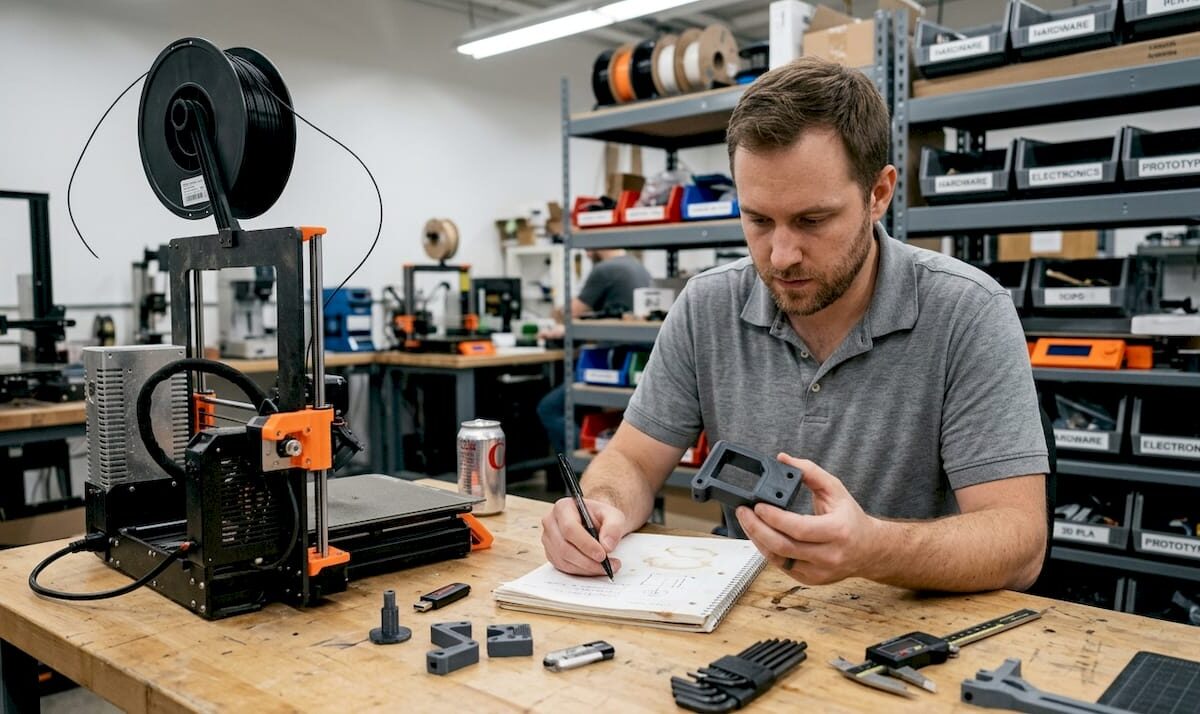
Technician reviewing 3D printed prototype at workshop desk

Why Print Accuracy Is Critical for 3D Prototyping


TL;DR:

  • Print accuracy measures how closely a 3D printed part matches CAD design dimensions.
  • Layer height, print speed, material shrinkage, and slicer calibration are key factors affecting accuracy.
  • Incorporating process control and topology optimization enhances reliability and reduces dimensional errors.

A single 0.2mm dimensional error seems insignificant on paper. In practice, it can mean a snap-fit assembly that won’t close, an engineering jig that wobbles under load, or a costly round of reprints that blows your project timeline. For product developers and manufacturers, this is not a hypothetical situation. It happens more often than most teams want to admit. The misconception is that 3D printing is rapid and “close enough” by nature. But when you’re validating a functional prototype or preparing for short-run production, close enough is never actually good enough. This guide explains what print accuracy really means, what drives it, and how to build it into every stage of your workflow.

Table of Contents

Key Takeaways

Point Details
Print accuracy defined Print accuracy is how closely your 3D part matches your design—critical for fit and function.
Settings matter most Layer height, print speed, and material choice determine accuracy much more than printer brand.
Material choice impacts results PLA and PETG offer better dimensional stability than ABS, reducing warping and shrinkage.
Advanced methods boost reliability Using topology optimization and process-aware tools produces more consistent and dependable prints.

What does print accuracy mean in 3D printing?

With the stakes clear, let’s define exactly what print accuracy means and why it isn’t just another technical buzzword.

Print accuracy describes how closely a finished 3D-printed part matches the original design dimensions in your CAD file. If your model calls for a 50mm hole and the printed result measures 49.6mm, you have an accuracy gap. That gap matters enormously once parts need to fit together, pass inspection, or meet a functional specification.
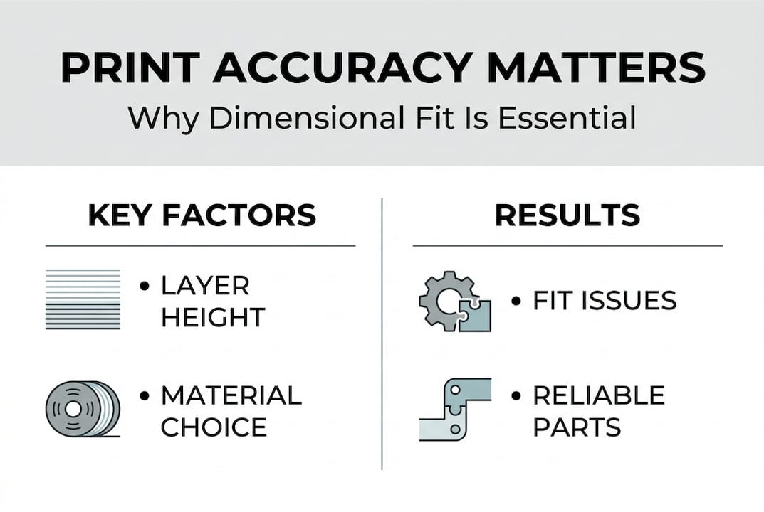
Infographic showing print accuracy essentials and results

It helps to distinguish accuracy from two related concepts. Precision refers to repeatability, meaning how consistently a printer reproduces the same result across multiple runs. Resolution refers to the smallest detail the printer can physically produce, typically expressed in microns. A printer can have high resolution but poor accuracy if it consistently prints features that are the wrong size. A machine can be precise but inaccurate if every part comes out 0.3mm too wide, every single time.

Why does a 0.2mm error wreck a snap-fit prototype? Because snap-fits operate within tight elastic deformation windows. Even a slight oversize on a cantilever arm can prevent engagement entirely. For engineering jigs used to hold, align, or guide other components, dimensional deviation means the jig introduces rather than eliminates error into your process.

Several variables directly control how accurate a print turns out:

  • Layer height: Layer height most significantly affects width and height errors in printed parts
  • Print speed: Faster movement reduces material control and increases deviation
  • Bed leveling: An uneven bed creates first-layer inconsistencies that propagate upward
  • Material shrinkage: All thermoplastics contract as they cool, some more than others
  • Nozzle temperature: Too low causes under-extrusion; too high causes material spread
  • Slicer calibration: Incorrect extrusion multiplier settings skew all feature sizes

Understanding the right 3D printing terminology before you start a project saves time and prevents costly assumptions.

Pro Tip: Before committing a design to a batch run, always compare your CAD tolerances to the documented capability of the printer and material you plan to use. A printer rated for ±0.2mm tolerance should never be trusted for a part that requires ±0.05mm fits without prior test prints.

Major factors that impact print accuracy

Now that it’s clear what accuracy means, let’s see what actually drives accurate and inaccurate results in 3D printing.

Empirical testing gives us the clearest answers. Research on FDM printing with PLA on a Prusa MK4 found that low speed, high temperature, and thin layers such as 20 to 40mm/s, 230°C, and 0.05mm layers delivered the best dimensional accuracy across tested parameters. That’s a meaningful benchmark for anyone running precision work.

Here’s how those findings translate into a practical parameter reference:

Parameter Optimal value for accuracy Effect of deviation
Layer height 0.05 to 0.10mm Thicker layers increase width and height error
Print speed 20 to 40mm/s Higher speed degrades material control
Nozzle temperature 230°C (for PLA) Lower temps cause under-extrusion and gaps
Bed temperature 60°C (for PLA) Incorrect temp causes warping and layer shift
Infill pattern Rectilinear or grid Complex patterns increase internal stress

Beyond settings, physical and process variables also play a major role:

  1. Design review: Check for features that exceed your printer’s capability before slicing
  2. Test piece: Print a calibration cube or representative feature before the full part
  3. Measurement: Use calipers to check test pieces against CAD dimensions before approving a run
  4. Slicer adjustment: Apply compensation values for known shrinkage or offset errors
  5. Post-processing review: Measure critical dimensions after any surface finishing or heat treatment

For guidance on matching material to tolerance requirements, the filament selection for precision guide covers real-world selection logic for demanding applications. If you’re still deciding between materials, see the breakdown of PLA, PETG, or ABS performance for functional parts.

Pro Tip: When dimensional accuracy is critical, reduce layer height and print speed before adjusting any other parameter. These two settings have the most direct and measurable impact on output fidelity.

Material selection and dimensional stability

Even with dialed-in settings, your material pick can make or break dimensional accuracy. Let’s see why.

Every thermoplastic shrinks as it transitions from molten to solid. The rate and consistency of that shrinkage determines how much the final part deviates from the design. Some materials are far more forgiving than others.
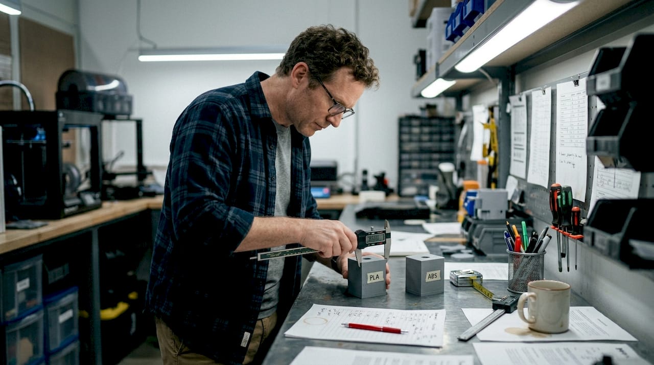
Engineer measuring 3D printed PLA and ABS blocks

Material Shrinkage rate Warping risk Best use cases
PLA Low (0.2 to 0.4%) Low Prototypes, display models, snap-fits
PETG Low to medium (0.3 to 0.5%) Low to medium Functional parts, mild chemical exposure
ABS High (0.7 to 1.6%) High Heat-resistant parts, post-processed components

Warping is the biggest accuracy threat from thermal behavior. Warping primarily comes from uneven cooling and shrinkage, and is best controlled with even cooling, adhesion aids, and choosing low-shrink materials like PLA or PETG when tolerances are tight.

“Warping doesn’t just ruin surface finish. It changes the geometry of a part in ways that are nearly impossible to correct after the fact. One curled edge on a mating surface can cascade into a full fit failure during assembly.” — Dimensional reliability perspective from materials engineering practice

Strategies to reduce warping and protect dimensional stability:

  • Use a heated enclosure for ABS and other high-shrink materials to slow and equalize cooling
  • Apply bed adhesion solutions such as glue stick, PEI sheets, or hairspray for better first-layer grip
  • Reduce part cooling fan speed for materials prone to layer delamination from rapid quenching
  • Orient parts to minimize large flat areas contacting the bed when using high-shrink filaments
  • Use brim or raft supports to anchor edge geometry during printing

One common overcorrection: teams add enclosures when printing low-shrink materials like PLA in cool environments. For most PLA prints, enclosures can actually trap heat and cause softening near the top layers. Know your material’s actual needs before defaulting to every countermeasure at once.

If you’re still narrowing down your options, the decision framework for choosing between PLA, PETG, and ABS breaks down dimensional trade-offs clearly. You can also explore what can be printed to see how material choice maps to real part applications.

Advanced methods: Topology optimization and process control

For truly reliable, repeatable parts, accuracy must extend beyond setup and materials. Here’s how modern approaches help.

Topology optimization is a computational design method that removes unnecessary material from a part while maintaining its structural performance. For 3D printing, it goes further than weight reduction. When the optimization algorithm incorporates the actual behavior of the printer, including how the print head deposits material and how bonding between layers works, the resulting geometry is fundamentally better suited to being printed accurately.

MIT’s advanced technique incorporates print head limitations and inter-layer bonding constraints directly into the topology optimization process, reducing deposition errors and making complex parts more reliable as a result. This is a significant shift from designing a part and hoping the printer handles it, to designing a part that the printer can actually execute with precision.

For manufacturers, the practical benefits are real:

  • Fewer failed prints: Designs that account for printer behavior fail less often mid-run
  • Less over-deposition: Optimized geometries reduce material buildup in corners and transitions
  • More repeatable outcomes: Process-aware designs perform consistently across multiple batches
  • Lower post-processing burden: Parts that print accurately need less sanding, filling, or rework
  • Better structural performance: Optimized designs maintain strength without compensating wall thickness

Process-aware slicing tools are also evolving. Modern slicer software increasingly allows users to input material behavior profiles so the tool can compensate for known shrinkage rates before the file is ever sent to print. Pairing this capability with topology-optimized geometry creates a workflow where accuracy is built in, not chased after.

For more on applying these principles to short-run work, the low-volume manufacturing tips resource covers batch consistency in detail. The designing for reliability guide addresses design-stage decisions that prevent dimensional problems before printing starts.

Why most teams underestimate print accuracy and how to shift your approach

Here’s the uncomfortable reality: most teams treat print accuracy as a printer problem, not a process problem. When a part comes out wrong, the instinct is to adjust a setting or switch machines. But accuracy failures are almost always systemic. They compound across decisions made in design, material selection, slicer setup, and even how results are measured and recorded.

Small errors are particularly dangerous because they feel correctable. A 0.3mm offset seems easy to absorb with a chamfer or a filed edge. But in a multi-part assembly, chain tolerance issues stack. What started as a minor gap at one interface becomes a structural misalignment two components later. By then, the cost of correction has multiplied.

Process discipline beats post-print correction every time. Log your print parameters, measure actual outputs, and compare them to design intent on every meaningful run. Never assume one batch mirrors the last. Filament lots vary, ambient temperature changes, nozzles wear. The low-volume accuracy approach we apply at CC 3D Labs reflects exactly this discipline.

Pro Tip: Keep a simple print log with layer height, speed, temperature, material lot, and measured output dimensions. Over time, this data reveals patterns that setting changes alone never will.

The teams that produce the most reliable prototypes are not the ones with the best printers. They’re the ones who treat accuracy as a non-negotiable standard at every stage, not an afterthought.

Get reliable prototypes with print-perfect accuracy

If you’re ready to leave inconsistency behind and prioritize accuracy, here’s how to take the next step.

At CC 3D Labs, we build dimensional accuracy into every project from file review through final inspection. Whether you need a single precision prototype or a short production run with tight tolerances, our team works through the exact settings and material choices covered in this guide on every job.

https://cc3dlabs.com

Explore our professional 3D printing services to see the full range of capabilities we bring to prototyping and functional part production. If you need parts fast, on-demand 3D prototyping gets you from file to finished part with zero guesswork on accuracy. And if you want to design for the best possible outcome from the start, our reliable print design tips give you a solid foundation before you ever send a file.

Frequently asked questions

What is the difference between print accuracy and precision?

Print accuracy differs from precision in a fundamental way: accuracy measures how closely a part matches the intended design dimensions, while precision measures how consistently those results repeat from one print to the next.

How much does layer height affect 3D print accuracy?

Layer height is the most significant factor for width and height errors in FDM prints. Thinner layers produce noticeably better dimensional fidelity, especially on features with fine detail or tight tolerances.

Why do some prints warp more than others?

Warping is primarily from thermal shrinkage and uneven cooling during printing. PLA and PETG shrink less than ABS, but proper bed adhesion, enclosure use, and cooling management can reduce warping across all common filament types.

How can topology optimization improve print reliability?

MIT’s technique incorporates real-world print constraints into the design optimization process, which reduces deposition errors and makes complex parts more structurally reliable. It shifts accuracy from a post-print correction problem to a pre-print design solution.
Engineer oversees 3D printing prototype process

Step-by-Step 3D Printing: Guide to Quality Prototypes


TL;DR:

  • Proper setup and material choice are essential to prevent common 3D print failures.
  • Workflow stages from CAD to testing greatly influence prototype accuracy and reliability.
  • Continuous iteration and analysis of failures lead to better scaling and production-ready parts.

Turning a digital design into a functional prototype feels straightforward until your first print warps off the bed, critical holes print undersized, or a snap-fit snaps wrong. Every stage of the 3D printing workflow carries real consequences for product developers and engineers: a miscalibrated printer or a poorly sliced file can cost you days and materials. This guide walks you through the full process, from CAD modeling to final evaluation, with expert-backed strategies, troubleshooting shortcuts, and optimization tips that help you build reliable, repeatable results. Whether you’re prototyping a single concept or preparing for batch production, the framework here is built to reduce risk at every step.

Table of Contents

Key Takeaways

Point Details
Plan before printing Success depends on preparing your CAD model, picking the right material, and verifying all printer settings and requirements.
Follow a proven workflow Move step-by-step from design to slicing, material choice, printing, post-processing, and testing for repeatable quality.
Optimize with iteration Expect to run two to four prototype cycles, incorporating testing feedback each time before moving to production.
Avoid common pitfalls Check for undersized holes, wall thickness, and correct build orientation to reduce failures and improve performance.
Leverage expert resources When in doubt, consult specialized guides or service providers to troubleshoot, optimize, and scale your 3D printing process.

Understand prerequisites and materials for 3D printing success

Before you print a single layer, your workflow needs a solid foundation. The standard prototyping process covers CAD modeling, slicing, material selection, printing, post-processing, and evaluation. Skipping or rushing any of these stages is where most prototype failures originate. Getting your tools, materials, and knowledge aligned upfront is the fastest way to avoid expensive rework later.

Here’s what you need in place before starting:

  • 3D printer: Calibrated, with a verified build plate level and nozzle condition
  • CAD software: Fusion 360, SolidWorks, or equivalent with export to STL/STEP
  • Slicer software: PrusaSlicer, Cura, or Chitubox depending on your technology
  • Filaments or resin: Matched to your functional requirements (PLA for concept models, PETG or Nylon for functional parts)
  • Post-processing tools: Deburring tools, sandpaper, IPA for resin, heat gun for warping correction
  • Calipers: Digital, for dimensional verification after every print

Material and tool selection is where engineers often underestimate complexity. Choosing PLA because it’s easy to print, then testing it under load, is a common mismatch. If you’re designing reliable 3D prints, material selection must track directly to end-use conditions, not just printability.

Tool/Material Purpose Best prototype stage
FDM printer (0.4mm nozzle) Concept and functional prototypes Early to mid stage
PLA/PETG filament Form and fit testing Concept to functional
Nylon/ASA filament Mechanical and environmental testing Functional validation
Resin (SLA) High-detail, tight-tolerance parts Fit checks, visual models
Digital calipers Dimensional verification All stages
Slicer software Toolpath and support generation All stages

For a deeper breakdown of material options and print settings, the filament printing guide covers the most common engineering filaments and when to use each.

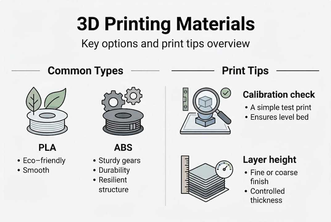
Infographic showing 3D printing materials and tips

Pro Tip: Always run a printer calibration check, including first-layer height and extrusion multiplier, before starting any new material or batch. A 5-minute check prevents hours of failed prints.

Step-by-step process: From CAD to finished part

With the right setup, you’re ready to move through each key phase with confidence. The end-to-end workflow follows six stages: CAD modeling, slicing, technology and material selection, printing, post-processing, and testing. Each phase feeds the next, so a weak link early compounds downstream.

  1. CAD modeling: Design with manufacturing in mind. Wall thicknesses above 1.2mm for FDM, clearances of 0.2 to 0.4mm for mating parts, and no unsupported overhangs beyond 45 degrees.
  2. Slicing: Convert your STL to toolpaths. Set layer height, infill, supports, and print speed. Layer height is the vertical resolution of each printed layer, typically 0.1 to 0.3mm for FDM.
  3. Technology and material selection: Match the process to the requirement. Use choosing the right 3D printing process as a reference when requirements shift.
  4. Printing: Monitor the first few layers. Adhesion failures and stringing are easiest to catch and correct early.
  5. Post-processing: Remove supports, sand critical surfaces, cure resin parts under UV, or anneal Nylon for dimensional stability.
  6. Testing and iteration: Measure, fit-check, and stress-test before moving to the next design revision. Review rapid prototyping fundamentals for structured iteration strategies.

Understanding the differences between technologies is critical. Mechanical property studies confirm that process choice directly impacts part strength and isotropy (uniformity of mechanical properties in all directions).

Technology Typical tolerance Layer height Relative cost Best use
FDM ±0.2 to 0.5mm 0.1 to 0.3mm Low Functional, structural prototypes
SLA ±0.05 to 0.15mm 0.025 to 0.1mm Medium High-detail, tight-fit parts
SLS ±0.1 to 0.3mm 0.1mm High Durable, complex geometry

The FDM vs SLA vs SLS comparison shows that tolerances, costs, and mechanical properties vary significantly across technologies, so aligning your choice to your validation stage matters.

Pro Tip: Print a small test coupon, a simple block with the key features of your part, before committing to a full prototype run. This catches fit and tolerance issues in under 20 minutes.

Troubleshooting, optimization, and expert shortcuts

Now that the workflow is clear, let’s make sure you avoid the missteps that slow down iteration cycles and degrade part quality. Most print failures trace back to a short list of repeatable design or setup errors.

Common errors to watch for:

  • Holes printing undersized by 0.1 to 0.3mm due to material expansion and toolpath offset
  • Thin walls below 0.8mm that fail to print or print inconsistently
  • Incorrect part orientation that puts layer lines perpendicular to the primary load direction
  • Inadequate clearances between mating parts, especially snap-fits and press-fits
  • Layer height set above 75% of nozzle diameter, which reduces inter-layer bonding

Common FDM design issues include Z-axis anisotropy (weakness perpendicular to the build plate), undersized holes, and thin-wall failures. These are not random. They are predictable and preventable with the right design rules.

For optimization, the levers that matter most are infill pattern, print speed, and part orientation. Expert print settings recommend 20 to 40% gyroid or cubic infill for strength-to-weight balance, reduced print speeds for load-bearing walls, and orienting critical features in the XY plane for tightest tolerances.

Aligning your primary load path with the XY plane is the single most impactful orientation decision you can make for FDM parts. Z-direction strength is always the weakest link.

For low-volume manufacturing, consider a hybrid approach: 3D print the form and fit prototype, then machine critical mating surfaces for precision. This keeps iteration fast while hitting tight tolerances where it counts. When evaluating which approach fits your project, finding the best print job for your specific part geometry and material can save significant time.

Also, dimensional accuracy varies by material and color. Black filament consistently delivers the lowest dimensional deviation in FDM, making it the go-to choice when precision is the priority.

Pro Tip: When printing functional FDM parts, use black filament for your validation round. The carbon pigment improves layer adhesion and reduces dimensional error compared to lighter colors.

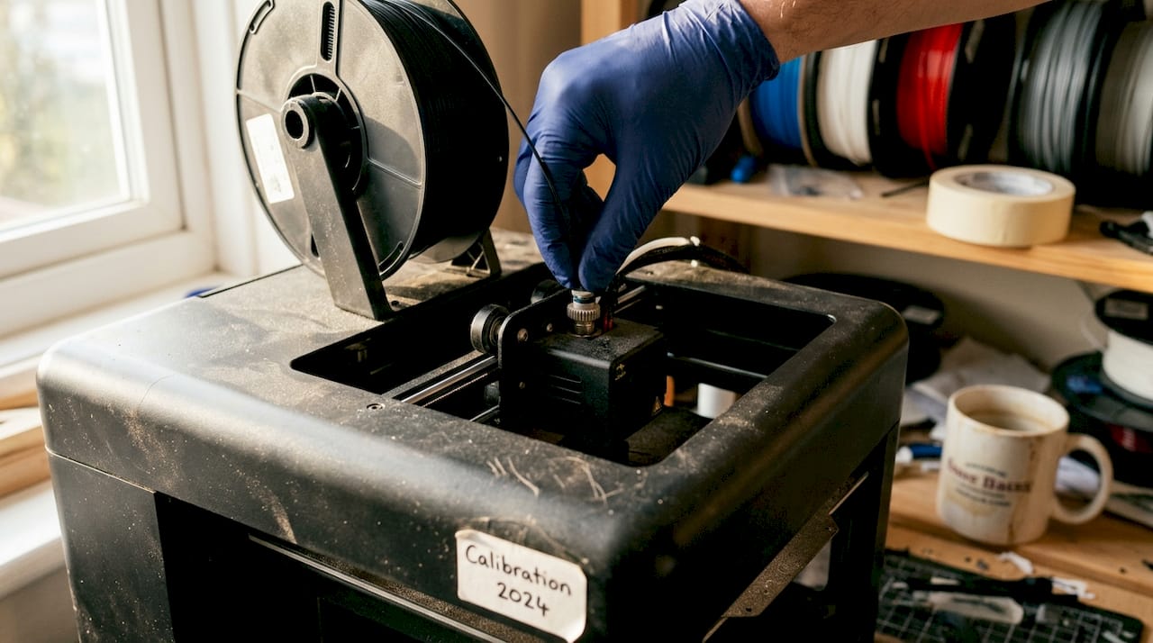
Detail of black filament for FDM printer

Evaluation, iteration, and scaling for production

With knowledge of preventing and addressing common issues, you’ll want to ensure your parts truly perform and are ready for scaling. Validation is not a single checkpoint. It’s a structured sequence of tests that confirms your prototype meets real-world requirements before you commit to production tooling or larger batch orders.

Testing checkpoints for every prototype:

  • Dimensional check: Measure all critical features with calipers or a CMM (coordinate measuring machine)
  • Mechanical fit: Assemble mating parts and verify clearances, snap-fits, and fastener holes
  • Visual inspection: Check for layer delamination, warping, incomplete infill, or surface defects
  • Functional stress test: Apply expected loads or environmental conditions to confirm performance
  • Material validation: Confirm the prototype material matches production material properties

Empirical data for additive manufacturing provides benchmarks for SLA flexural strength and FDM tensile performance, giving you reference values to compare against your test results.

Prototype stage Typical iteration cycles Primary focus
Concept model 1 to 2 Form and fit
Functional prototype 2 to 4 Fit, function, strength
Pre-production validation 1 to 2 Material match, tolerance

For high-quality prototypes, plan for two to four iteration cycles, with each round using materials that match your intended production process. MJF (Multi Jet Fusion) offers faster cycle times and more isotropic parts than FDM for production-like validation.

When you’re ready to scale, the technology decision matters again. FDM works well for low-volume runs of large, structural parts. SLS and MJF become the better choice for complex geometry, tight tolerances, or batch quantities above 20 to 50 units. Browse real-world prototype examples to see how different technologies perform across part types.

For on-demand print solutions, understanding what can be printed across different technologies helps you plan your scaling path before committing to a production process.

The real challenges and opportunities in step-by-step 3D printing

Here’s what most guides won’t tell you: the engineers who get the best results from 3D printing are not the ones chasing the latest printer or fastest technology. They’re the ones who treat every failed print as a data point, not a setback.

Perfecting your CAD design and printer setup consistently outperforms any speed or technology upgrade. A well-designed part on a mid-range FDM printer beats a poorly designed part on a high-end SLA machine every time. The discipline of iteration, reviewing failures, adjusting one variable at a time, and documenting results, is what separates engineers who scale successfully from those who stay stuck in the prototype loop.

Cross-disciplinary thinking matters here too. Understanding how your end-use environment affects material choice, how your manufacturing process influences design constraints, and how your testing protocol connects to real-world loads gives you leverage that no slicer setting can replicate. Review rapid prototyping realities to ground your workflow in practical expectations. The counter-intuitive truth is that your worst prints, the ones that delaminated, warped, or failed fit checks, are your most valuable teachers if you analyze them systematically.

Get expert support for your 3D printing projects

If you’re ready to push your prototype to the next level but want to reduce guesswork and risk, professional support is one click away. At CC 3D Labs, we handle every stage of the process, from design optimization and material selection to finished functional parts with tight tolerances.

https://cc3dlabs.com

Our team works directly with product developers and engineers to minimize print failures, accelerate iteration cycles, and match your prototype to production-grade requirements. Whether you need a single concept model or a batch of functional parts, our professional 3D printing services are built for your workflow. Explore on-demand prototypes to get started, or review our printing terminology guide to align your project specs before reaching out.

Frequently asked questions

What are the most common 3D printing mistakes and how can I avoid them?

Typical print failures include undersized holes, inadequate clearances, thin walls, and Z-axis weakness from layer anisotropy. Review your CAD file against FDM design rules and always run a test coupon before committing to a full prototype.

How do I pick the right 3D printing technology for my prototype?

Base your choice on required precision, mechanical strength, and batch size. FDM, SLA, SLS, and MJF each occupy different positions on the cost, accuracy, and throughput spectrum, so match the technology to your current validation stage.

How many iterations does a high-quality prototype require?

Most prototypes reach production readiness after two to four iterations, with each round using materials and processes that closely match the intended production method.

What is the advantage of using black filament for FDM prints?

Black filament consistently shows the lowest dimensional deviation in FDM printing, making it the most reliable color choice for parts where precision and tight tolerances are critical.

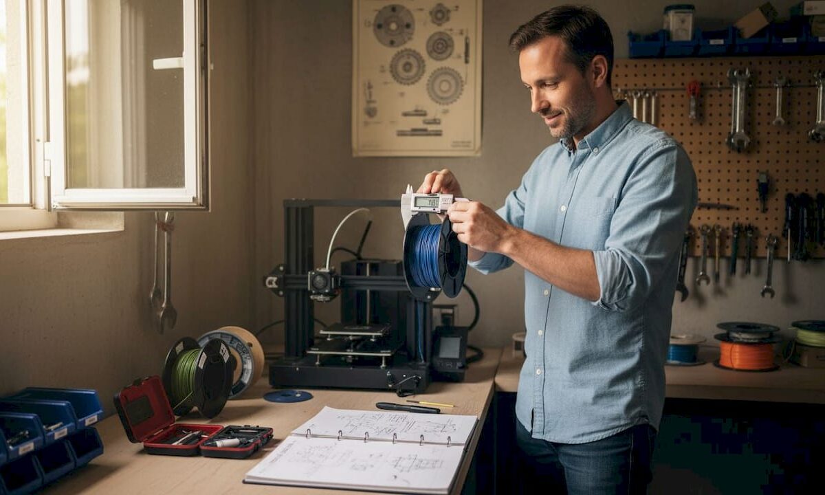
Engineer checks filament tolerance with calipers

Custom filament printing guide: precision for prototypes


TL;DR:

  • Filament diameter tolerance of ±0.02mm ensures consistent, professional-grade 3D printing results.
  • Proper material choice, printer calibration, and controlled environment are crucial for accuracy and repeatability.
  • Systematic verification and measurement across batches prevent variability and enhance manufacturing reliability.

Even a 0.05mm variation in filament diameter can push a prototype over tolerance, trigger failed prints, and delay your product launch by days or weeks. For product developers and small manufacturing teams, that is not a minor inconvenience. It is a real business cost. ±0.02mm filament tolerance is the benchmark separating consistent, professional-grade output from frustrating batch failures. This guide walks you through every stage of custom filament printing, from material selection and printer setup to parameter tuning and quality verification, so you can produce parts that hold tolerance and hold up under real-world conditions.

Table of Contents

Key Takeaways

Point Details
Choose the right filament Proper filament type and tolerance are the foundation for consistent, successful prints for prototypes and production.
Calibrate and control environment Printer calibration and environmental controls are just as critical as material choice for avoiding common failures.
Optimize print parameters Fine-tuning orientation and slicer settings can dramatically boost part strength and accuracy.
Verify print quality Regular, measured quality checks catch inconsistencies early, ensuring confidence in every print run.
Expert help accelerates results Partnering with a specialized 3D printing service speeds up learning, minimizes costly mistakes, and delivers reliable prototypes.

Understand filament types and requirements

Choosing the right filament is not just about matching color to your brand palette. Material selection determines whether your functional prototype survives a stress test, fits into an assembly, or ships with consistent surface quality across a batch. Getting this decision right upfront saves you rework time and material cost.

Core filament types and where they fit:

  • PLA: Easy to print, dimensionally stable, ideal for concept models and display prototypes. Not suited for heat or mechanical stress.
  • PETG: Balances strength and printability. Great for functional parts, but it is hygroscopic and requires drying before use to avoid bubbles and stringing.
  • ABS: Tough and heat-resistant, essential for functional housings and mechanical parts. Needs an enclosure to prevent warping.
  • Nylon: High impact resistance and flexibility, but absorbs moisture aggressively. Drying is non-negotiable.
  • Carbon fiber, glow-in-the-dark, and metal-filled filaments: Abrasive composites that demand hardened steel nozzles, or you will wear through a standard brass nozzle within hours.
Filament Enclosure needed Drying required Nozzle type
PLA No Rarely Brass
PETG Optional Yes Brass or hardened
ABS Yes Rarely Brass
Nylon Yes Yes Hardened steel
Carbon fiber Yes Yes Hardened steel

Tolerance matters more than most developers realize. A filament rated at ±0.02mm produces under 1% volumetric variation, keeping flow rates consistent across long print runs. Once you step down to ±0.05mm, you are looking at nearly 3% volumetric swing, which shows up as over-extrusion on some layers and under-extrusion on others. You can find more material-specific advice in our prototyping filament guide or dig into a side-by-side breakdown with PLA vs PETG vs ABS.

Color additives also affect printability. Dark pigments, particularly black, absorb more heat and may require a slightly lower temperature than a natural or white version of the same material. Always run a temperature tower when switching colorways on a critical production run.

Pro Tip: Store all hygroscopic filaments in sealed containers with silica gel desiccant between print sessions. Even a few hours of open-air exposure in a humid environment can ruin a spool of Nylon or PETG.

Set up your printer for custom filament printing

Once your material is chosen, your printer and workspace need matching attention. A well-selected filament will still produce poor results if the hardware delivering it is out of calibration or operating in an uncontrolled environment.

Start with these setup steps in order:

  1. Level the print bed. A bed that is even 0.1mm off across its surface will cause adhesion failures on the first layer, which cascades into every layer above it.
  2. Clean the hot end. Residual material from a previous filament run causes contamination, especially when switching from a high-temperature material to a lower-temperature one.
  3. Check the extruder tension. Too tight and you grind the filament. Too loose and steps are skipped. Both cause inconsistent flow.
  4. Calibrate your extruder steps per mm. Mark 100mm of filament, extrude it, and measure what actually moved. Adjust until the numbers match.
  5. Set nozzle diameter to match your job. Abrasive filaments require a hardened nozzle. Standard brass erodes fast under carbon fiber or metal-filled materials.

Environment matters too. ±0.05mm diameter variation creates a 2.8% volumetric swing that no software setting can fully compensate for, but ambient temperature swings make things worse. ABS requires a fully enclosed printer to maintain a consistent chamber temperature and prevent warping from drafts. Hygroscopic materials need controlled humidity both in storage and during printing.

A stable printer in a controlled workspace produces more consistent results than a high-end machine sitting in a drafty, humid shop floor. Environment is not optional.

Printer check What to look for Tool needed
Bed level Even first layer adhesion Feeler gauge or probe
Extruder calibration 100mm extrusion accuracy Ruler or calipers
Hot end cleanliness No residue or discoloration Cold pull or cleaning filament
Nozzle condition No erosion on tip Visual inspection

For batch production specifically, you will want to build a pre-run checklist. Our low-volume manufacturing tips walk through setup routines designed to keep quality consistent across dozens of parts. If you are deciding between printer types for your workflow, choosing the right printing type covers that decision in detail.

Pro Tip: Run a small calibration cube before every new filament spool or environmental change. It takes five minutes and tells you immediately if something has drifted.

Woman calibrates 3D printer for new filament

Optimize print parameters for strength and accuracy

Once hardware is ready, fine-tuning print parameters maximizes your results. Slicer settings are where most developers either gain or lose the edge on part performance.

Orientation is the most underestimated variable in filament printing. FDM parts are anisotropic, meaning they are stronger along the layer plane than perpendicular to it. Placing a part so its primary load axis runs parallel to the print bed increases stiffness dramatically. Parameter optimization, including orientation and layer height adjustments, has been shown to boost part stiffness by 81 to 128%. That is not a marginal gain. It is the difference between a prototype that passes mechanical testing and one that snaps during the first use cycle.

Follow this sequence when dialing in parameters for a new job:

  1. Set orientation first. Analyze load direction and place the strongest axis in line with expected stress.
  2. Choose layer height. Thinner layers (0.1mm to 0.15mm) improve surface detail and interlayer bonding for functional parts. Thicker layers (0.2mm to 0.3mm) speed up prototyping when detail is less critical.
  3. Tune temperature. Advanced materials like PETG and Nylon run hotter and benefit from a temperature tower to find the sweet spot for flow and layer adhesion without stringing.
  4. Set print speed. Slower speeds improve accuracy. For precision prototypes, drop below 40mm/s on perimeters.
  5. Adjust cooling. PLA needs active cooling. ABS and Nylon need minimal or no cooling to prevent layer delamination.

Black filaments deserve a specific note. Because of their higher heat absorption, black variants of the same base material often need a temperature reduction of 5°C to 10°C compared to neutral colors. Skipping this step leads to over-melting and oozing on fine features.

For guidance on building print-ready geometry that supports these parameters, our resource on designing reliable prints and optimizing your CAD workflow are worth your time before you hit slice.

Pro Tip: Never rely on a slicer’s default profile for a production run. Always run a first-article part with your specific filament, nozzle, and environment before committing to a full batch.

Quality verification and troubleshooting

With parameters optimized, assess and fix your results for business-grade consistency. Printing one good part is not the goal. Printing forty identical good parts is.

Start with visual inspection on every part:

  • Layer lines: Should be uniform in height and spacing. Inconsistent lines point to extruder slippage or filament diameter variation.
  • Wall smoothness: Rough or pitted walls signal moisture in the filament or a clogged nozzle.
  • Color consistency: Streaks or shade shifts mid-print indicate contamination or temperature instability.

After visual checks, measure. Use calipers to verify critical dimensions against your CAD model. Tolerance variations at ±0.02mm create under 1% dimensional error, while ±0.05mm filament pushes that beyond 2.8%. For parts going into assemblies, even 0.1mm of deviation can mean a misfit. Document your measurements across each batch so you can track drift over time.

Iteration is not failure. Running three calibration parts before a 50-piece batch is a quality investment, not wasted material.

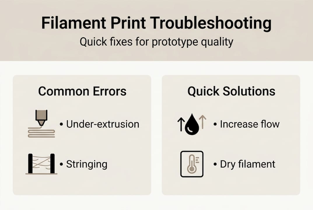
Common error Symptom Solution
Under-extrusion Thin walls, gaps in layers Increase flow rate, check extruder tension
Over-extrusion Blobbing, rough surfaces Reduce flow rate or temperature
Warping Lifted corners Use enclosure, increase bed adhesion
Stringing Fine threads between features Increase retraction, reduce temperature
Layer delamination Cracks between layers Increase temperature, reduce cooling

Infographic with filament troubleshooting and solutions

For visual references of what precision output actually looks like at each stage, our prototype quality examples show real parts printed to specification.

Why most guides miss what actually matters in custom filament printing

Most online guides focus on slicer profiles and temperature charts. Those things matter, but they are not the ceiling. The real ceiling for manufacturing reliability is filament consistency and systematic verification across batches.

Here is what experience teaches you: even a premium slicer profile running on a well-calibrated machine cannot compensate for a filament spool with inconsistent diameter. If the material feeding into your nozzle varies by 0.05mm or more throughout the spool, your flow rate fluctuates regardless of your settings. You can tune all day and still see surface variation on parts 20 and 40 that looked fine on parts 1 and 2.

The second thing most guides skip is the difference between a successful single print and a repeatable process. For a product developer or small manufacturer, repeatability is everything. One good prototype means little if your next run of 30 parts has visible variation. Build a verification step into every run. Measure early, measure often, and document what you find. That process discipline is what separates hobbyist output from professional manufacturing output.

Our additional prototyping strategies go deeper into building that kind of repeatable workflow.

Take your custom filament printing further with CC3DLabs

If you are hitting the limits of what in-house printing can deliver for precision, batch consistency, or advanced materials, working with an experienced team changes the equation.

https://cc3dlabs.com

At CC3D Labs, near Philadelphia, we specialize in custom filament-based 3D printing for product developers and manufacturing teams who need parts that perform, not just parts that look right on a screen. Our 3D printing services cover everything from single prototypes to production runs, with material expertise and quality verification built into every job. Want to know what is possible before you commit? See our printing capabilities and browse real-world prototype case studies to see the standard we hold our work to. Reach out for a free estimate and let us help you get it right the first time.

Frequently asked questions

What is the ideal filament tolerance for precision 3D printing?

A filament diameter tolerance of ±0.02mm delivers the best print consistency for prototypes and low-volume manufacturing, keeping volumetric variation under 1%.

Why do some filaments require drying before printing?

Hygroscopic filaments like PETG and Nylon absorb moisture from the air, which causes bubbling, poor layer adhesion, and stringing unless the material is thoroughly dried before printing.

How does orientation impact 3D printed part strength?

Optimizing part orientation during slicing aligns the strongest axis with the load direction, with research showing stiffness improvements of up to 128% compared to default orientations.

How do you check if your print is accurate?

Measure critical dimensions with calipers and compare them to your CAD model. Tolerance variations above ±0.05mm can push dimensional error past 2.8%, which is unacceptable for assembly-fit parts.

Engineer preparing prototype for 3D scanning

3D Scanning Checklist: Ensure Accurate Prototypes & Parts


TL;DR:

  • Proper planning, environmental prep, and validation are essential to ensure accurate 3D scans.
  • Selecting the right scanner depends on part size, detail needed, and surface properties.
  • Rushing steps or skipping validation increases costly errors despite hardware quality.

One missed step in a 3D scanning workflow can send a prototype back to square one. For product developers and engineers, that means wasted hours, rework costs, and delayed production timelines. A structured checklist is not a bureaucratic formality; it is the difference between a scan you can trust and one that looks fine until the part fails tolerance checks on the shop floor. This guide walks through every critical phase: setting objectives, choosing the right scanner, preparing your environment, executing the scan, and validating results with objective metrics. Follow it consistently, and you will eliminate the most common sources of scanning error before they become expensive problems.

Table of Contents

Key Takeaways

Point Details
Define scanning requirements Clear goals and part specs are essential for selecting methods and validation metrics.
Match scanner to project Choose equipment based on part size and complexity for the highest accuracy.
Control prep and setup Careful part and environment preparation dramatically reduces errors and rescans.
Validate with metrics Use CF3D%, MD3D, and SQI3D to objectively confirm scan quality before moving to production.
Checklists prevent failures Following a robust checklist is more effective than relying solely on expensive scanners.

Set clear objectives and scan requirements

Every reliable 3D scan starts before you touch any hardware. The first step is defining exactly what you need the scan to accomplish, because that decision shapes every choice that follows.

Start by identifying the end use. A scan intended for a concept prototype has very different accuracy requirements than one destined for a production-ready part or a reverse-engineering workflow. Confusing these two contexts is one of the fastest ways to waste a scanning session.

Document the following before you begin:

  1. Part material and surface finish (matte, glossy, translucent, or metallic surfaces each require different handling)
  2. Overall dimensions and geometric complexity (simple prismatic parts versus freeform organic geometry)
  3. Required dimensional tolerance (what deviation is acceptable in millimeters or microns?)
  4. Downstream use (CAD comparison, mesh-to-print, inspection report, or reverse engineering)
  5. Deliverable format (STL, OBJ, STEP, or point cloud)

These five data points define your success criteria upfront. Without them, you are scanning blind.

Once you have your requirements documented, tie them to quantitative metrics. Quantitative metrics for 3D scanning research confirms you should always validate with Coverage Factor (CF3D%), Mean Distance (MD3D), and Scan Quality Index (SQI3D). CF3D% measures how much of the target surface your scan actually captured. MD3D quantifies the average deviation between your scan and the reference geometry. SQI3D combines multiple quality indicators into a single score for fast pass/fail decisions.

“Metric-based validation removes guesswork from the quality assessment process and creates a repeatable standard your entire team can apply.”

Setting these thresholds before the scan begins means you have an objective target to hit, not just a visual impression to judge. Understanding design accuracy and prototyping requirements is the foundation that makes every downstream decision faster and more defensible.

Pro Tip: Write your tolerance and metric thresholds directly on your scan request form. When multiple engineers are involved, this single habit eliminates the most common source of miscommunication between scanning and design teams.

Choose the right scanner and scanning method

With clear requirements in hand, the next step is selecting a scanner and scanning approach that fits those needs precisely. The wrong scanner type is not just a minor inconvenience; it can make it physically impossible to meet your documented tolerance requirements.

Here is a breakdown of the three most common scanner types used in engineering and product development:

  • Handheld laser scanners: Best for medium to large parts, complex assemblies, and on-site scanning. They offer flexibility and portability but typically deliver accuracy in the 0.05 to 0.1 mm range. Handheld laser scanners excel for prototypes up to 10 meters, while structured light scanners are the better choice for small, detailed parts.
  • Structured light scanners: Best for small to medium parts requiring high detail and tight tolerances. They project a pattern of light onto the surface and calculate geometry from the distortion. Accuracy can reach 0.01 mm or better, but they require a controlled environment and a stationary setup.
  • Photogrammetry: Best for very large objects or when portability is the priority. It uses overlapping photographs to reconstruct geometry. Accuracy is lower than laser or structured light methods, but it scales well and requires minimal equipment.

Matching the scanner to the part is not just about size. Consider these factors:

  • Surface reflectivity: Shiny or dark surfaces defeat most laser systems without preparation.
  • Feature size: Fine threads, sharp edges, or thin walls need structured light resolution.
  • Scan environment: Outdoor or production-floor scanning favors handheld systems.
  • Operator experience: Structured light systems have steeper learning curves.

Pro Tip: Do not let the scanner’s marketed accuracy spec be your only decision factor. Ask vendors for accuracy data on parts that match your geometry and surface type, not just flat reference artifacts.

If your project involves custom prototypes, understanding what makes the best print job for prototypes helps you align scanning precision with the print process you plan to use downstream. Similarly, reviewing how to choose the right printing type for production ensures your scan data will actually support the manufacturing method you intend to use.

Prepare the part and environment for scanning

Once you have the right scanner, expert results depend on methodical setup. This is the phase most engineers rush, and it is where most scan failures originate.

Follow this numbered preparation sequence every time:

  1. Clean the part thoroughly. Remove dust, oils, and loose debris. Even fine particles scatter laser light and introduce noise into the point cloud.
  2. Apply scanning spray if needed. Reflective, dark, or translucent surfaces require a temporary matte coating. Use a thin, even layer and allow it to dry completely.
  3. Secure the part with fixtures. Movement during scanning is the single biggest source of data misalignment. Use a turntable, magnetic fixture, or custom jig appropriate for the part geometry.
  4. Calibrate the scanner. Run the manufacturer’s calibration routine before every session, not just at the start of the day. Temperature changes affect optics.
  5. Set reference targets if required. Adhesive targets help the scanner track position across multiple scan passes on complex geometry.

Surface preparation and stable positioning are vital for reliable scans, and skipping either step creates problems that no amount of post-processing can fully correct.

Beyond the part itself, check these environmental factors:

  • Vibration: Isolate the scanning area from foot traffic, HVAC equipment, and nearby machinery.
  • Ambient light: Structured light scanners are sensitive to sunlight and fluorescent flicker. Use blackout curtains or scan in a dedicated room.
  • Background contrast: Place a neutral, non-reflective background behind the part to prevent the scanner from picking up stray geometry.
  • Temperature stability: Thermal expansion affects both the part and the scanner optics. Allow both to acclimate to room temperature before starting.

For a detailed look at what a controlled scanning environment looks like in practice, review our high quality 3D scan process guide. You can also explore our 3D Scanning Lab process or submit a 3D Scan Request Form to get professional support on your next project.

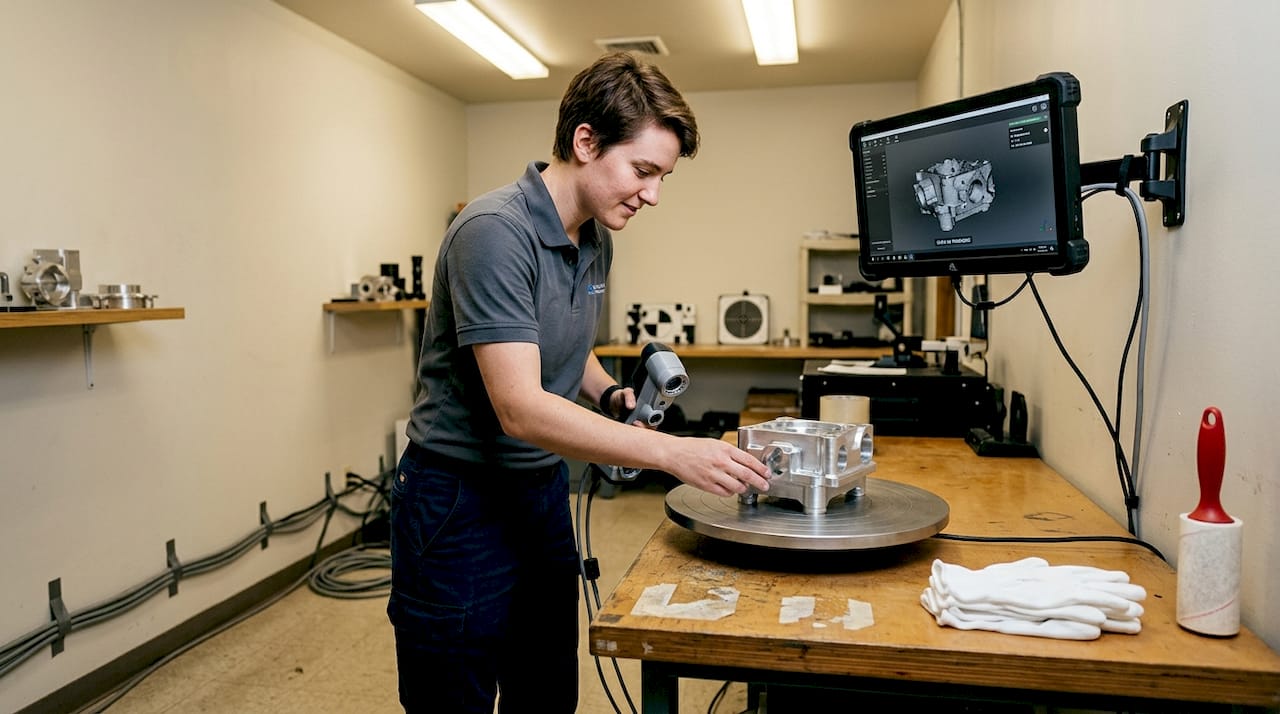
Technician prepping part in scanning room

Scan execution: capturing, validating, and optimizing data

With preparation complete, conducting the scan itself and validating results is where the checklist really proves its value. A clean setup does not guarantee a clean scan; you need a disciplined execution sequence.

Follow these steps in order:

  • Run an initial scan pass and review the raw mesh immediately. Do not wait until the end of the session to discover a problem area.
  • Check coverage visually and by CF3D% threshold. Any region below your target coverage percentage needs a re-scan pass before you move the part.
  • Identify and re-scan problem areas: undercuts, deep pockets, and thin walls are the most common trouble zones.
  • Align multiple scan passes using reference targets or software registration. Check alignment error before merging.
  • Export the validated mesh in the format your downstream workflow requires.

Here is a quick reference for the most common scan errors and how to address them:

Scan error Validation metric Corrective action
Missing surface coverage CF3D% below threshold Add scan passes from new angles
High deviation from reference MD3D exceeds tolerance Re-calibrate scanner, re-scan
Low overall quality score SQI3D fails Review all prep steps, repeat session
Mesh noise or spikes Visual + MD3D Reapply scanning spray, reduce ambient light
Misaligned scan passes MD3D between passes Re-register using reference targets

Validation metrics like CF3D%, MD3D, and SQI3D are essential for trustworthy scans, and applying them at each stage rather than only at the end catches errors while correction is still fast and cheap.

“A scan that passes visual inspection but fails metric validation is not a scan you can build a production part from.”

For export, use formats your CAD and manufacturing tools handle natively. Learning how to optimize workflow with CAD file formats prevents conversion errors that degrade scan accuracy. If you are newer to the terminology around scan outputs, the printing terminology for product developers guide clarifies common file type distinctions. For specialized applications like dental scanning standards, metric validation follows the same core principles but with even tighter tolerances.

Why most 3D scanning projects fail: The hidden checklist gaps

After working through hundreds of scanning projects, the pattern is clear: most failures are not hardware failures. They are process failures. The scanner was adequate. The operator was experienced. But someone skipped a step.

The three most common hidden gaps are rushing the setup phase, skipping metric validation in favor of visual approval, and assuming the scanner is inherently accurate enough without confirming it against your specific part geometry. Each of these feels like a time-saving shortcut in the moment and becomes a costly rework cycle later.

Skipped validation is a leading source of downstream part defects, and it is almost always avoidable. A five-minute metric check at the end of a scan session is far cheaper than discovering dimensional errors after a part has been printed or machined.

The uncomfortable truth is that a disciplined checklist on a mid-range scanner outperforms an ad-hoc process on a top-tier system every time. Hardware does not compensate for skipped steps. If you want to build a scanning workflow your team can trust, start with achieving high quality scans as your process baseline, then layer in metric validation as a non-negotiable exit criterion for every session.

Ready to streamline your 3D scanning workflow?

If your team is ready to move from ad-hoc scanning to a repeatable, validated process, CC 3D Labs is set up to support exactly that. We offer professional handheld 3D scanning (accuracy to ~0.1 mm), full prototyping, and expert guidance for product developers and engineers who need results they can build on.

https://cc3dlabs.com

Explore our 3D Scanning Lab services to see how we handle complex parts and tight tolerances. If your project needs both scanning and production, our full 3D printing services keep everything under one roof. And if you want to go deeper on best practices before you start, our high quality scan guide is the right next read. Get a free estimate and let us help you get it right the first time.

Frequently asked questions

What are the most important metrics for validating a 3D scan?

The key metrics are Coverage Factor (CF3D%), Mean Distance (MD3D), and Scan Quality Index (SQI3D). These three validation metrics quantify how complete and accurate your scan data is, giving you an objective pass/fail standard.

How do you select the right scanner for a specific part?

Base your choice on part size and required detail level. Scanner selection should match part size and complexity, with handheld lasers for larger prototypes, structured light for small intricate parts, and always confirm results with metric validation.

Why is environmental preparation important for 3D scanning?

Unstable or contaminated environments introduce noise, reflections, and misalignment errors that degrade scan accuracy. Surface and environmental prep is crucial for correct scans, and no post-processing step can fully recover data lost to a poor setup.

What mistakes commonly lead to poor scan quality?

Skipping preparation or validation reduces scan quality more than any hardware limitation. Using a mismatched scanner type for the part geometry is the third most frequent cause of rework.

How can engineers streamline 3D scanning workflows?

Standardize your setup sequence, define metric thresholds before each session, and treat the checklist as a non-negotiable process step. Detailed checklists and metric validation streamline workflows by catching errors early, when correction is fast and inexpensive.