
TL;DR:
- Proper setup and material choice are essential to prevent common 3D print failures.
- Workflow stages from CAD to testing greatly influence prototype accuracy and reliability.
- Continuous iteration and analysis of failures lead to better scaling and production-ready parts.
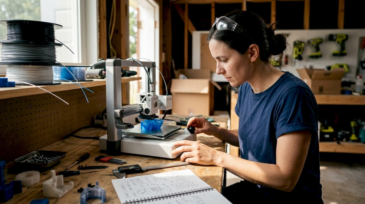
Turning a digital design into a functional prototype feels straightforward until your first print warps off the bed, critical holes print undersized, or a snap-fit snaps wrong. Every stage of the 3D printing workflow carries real consequences for product developers and engineers: a miscalibrated printer or a poorly sliced file can cost you days and materials. This guide walks you through the full process, from CAD modeling to final evaluation, with expert-backed strategies, troubleshooting shortcuts, and optimization tips that help you build reliable, repeatable results. Whether you’re prototyping a single concept or preparing for batch production, the framework here is built to reduce risk at every step.
Table of Contents
- Understand prerequisites and materials for 3D printing success
- Step-by-step process: From CAD to finished part
- Troubleshooting, optimization, and expert shortcuts
- Evaluation, iteration, and scaling for production
- The real challenges and opportunities in step-by-step 3D printing
- Get expert support for your 3D printing projects
- Frequently asked questions
Key Takeaways
| Point | Details |
|---|---|
| Plan before printing | Success depends on preparing your CAD model, picking the right material, and verifying all printer settings and requirements. |
| Follow a proven workflow | Move step-by-step from design to slicing, material choice, printing, post-processing, and testing for repeatable quality. |
| Optimize with iteration | Expect to run two to four prototype cycles, incorporating testing feedback each time before moving to production. |
| Avoid common pitfalls | Check for undersized holes, wall thickness, and correct build orientation to reduce failures and improve performance. |
| Leverage expert resources | When in doubt, consult specialized guides or service providers to troubleshoot, optimize, and scale your 3D printing process. |
Understand prerequisites and materials for 3D printing success
Before you print a single layer, your workflow needs a solid foundation. The standard prototyping process covers CAD modeling, slicing, material selection, printing, post-processing, and evaluation. Skipping or rushing any of these stages is where most prototype failures originate. Getting your tools, materials, and knowledge aligned upfront is the fastest way to avoid expensive rework later.
Here’s what you need in place before starting:
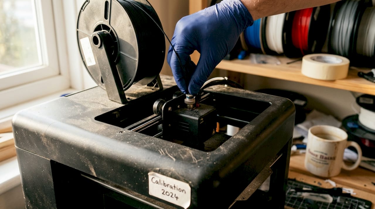
- 3D printer: Calibrated, with a verified build plate level and nozzle condition
- CAD software: Fusion 360, SolidWorks, or equivalent with export to STL/STEP
- Slicer software: PrusaSlicer, Cura, or Chitubox depending on your technology
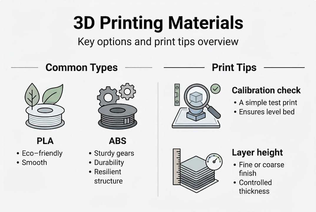
- Filaments or resin: Matched to your functional requirements (PLA for concept models, PETG or Nylon for functional parts)
- Post-processing tools: Deburring tools, sandpaper, IPA for resin, heat gun for warping correction
- Calipers: Digital, for dimensional verification after every print
Material and tool selection is where engineers often underestimate complexity. Choosing PLA because it’s easy to print, then testing it under load, is a common mismatch. If you’re designing reliable 3D prints, material selection must track directly to end-use conditions, not just printability.
| Tool/Material | Purpose | Best prototype stage |
|---|---|---|
| FDM printer (0.4mm nozzle) | Concept and functional prototypes | Early to mid stage |
| PLA/PETG filament | Form and fit testing | Concept to functional |
| Nylon/ASA filament | Mechanical and environmental testing | Functional validation |
| Resin (SLA) | High-detail, tight-tolerance parts | Fit checks, visual models |
| Digital calipers | Dimensional verification | All stages |
| Slicer software | Toolpath and support generation | All stages |
For a deeper breakdown of material options and print settings, the filament printing guide covers the most common engineering filaments and when to use each.
Pro Tip: Always run a printer calibration check, including first-layer height and extrusion multiplier, before starting any new material or batch. A 5-minute check prevents hours of failed prints.
Step-by-step process: From CAD to finished part
With the right setup, you’re ready to move through each key phase with confidence. The end-to-end workflow follows six stages: CAD modeling, slicing, technology and material selection, printing, post-processing, and testing. Each phase feeds the next, so a weak link early compounds downstream.
- CAD modeling: Design with manufacturing in mind. Wall thicknesses above 1.2mm for FDM, clearances of 0.2 to 0.4mm for mating parts, and no unsupported overhangs beyond 45 degrees.
- Slicing: Convert your STL to toolpaths. Set layer height, infill, supports, and print speed. Layer height is the vertical resolution of each printed layer, typically 0.1 to 0.3mm for FDM.
- Technology and material selection: Match the process to the requirement. Use choosing the right 3D printing process as a reference when requirements shift.
- Printing: Monitor the first few layers. Adhesion failures and stringing are easiest to catch and correct early.
- Post-processing: Remove supports, sand critical surfaces, cure resin parts under UV, or anneal Nylon for dimensional stability.
- Testing and iteration: Measure, fit-check, and stress-test before moving to the next design revision. Review rapid prototyping fundamentals for structured iteration strategies.
Understanding the differences between technologies is critical. Mechanical property studies confirm that process choice directly impacts part strength and isotropy (uniformity of mechanical properties in all directions).
| Technology | Typical tolerance | Layer height | Relative cost | Best use |
|---|---|---|---|---|
| FDM | ±0.2 to 0.5mm | 0.1 to 0.3mm | Low | Functional, structural prototypes |
| SLA | ±0.05 to 0.15mm | 0.025 to 0.1mm | Medium | High-detail, tight-fit parts |
| SLS | ±0.1 to 0.3mm | 0.1mm | High | Durable, complex geometry |
The FDM vs SLA vs SLS comparison shows that tolerances, costs, and mechanical properties vary significantly across technologies, so aligning your choice to your validation stage matters.
Pro Tip: Print a small test coupon, a simple block with the key features of your part, before committing to a full prototype run. This catches fit and tolerance issues in under 20 minutes.
Troubleshooting, optimization, and expert shortcuts
Now that the workflow is clear, let’s make sure you avoid the missteps that slow down iteration cycles and degrade part quality. Most print failures trace back to a short list of repeatable design or setup errors.
Common errors to watch for:
- Holes printing undersized by 0.1 to 0.3mm due to material expansion and toolpath offset
- Thin walls below 0.8mm that fail to print or print inconsistently
- Incorrect part orientation that puts layer lines perpendicular to the primary load direction
- Inadequate clearances between mating parts, especially snap-fits and press-fits
- Layer height set above 75% of nozzle diameter, which reduces inter-layer bonding
Common FDM design issues include Z-axis anisotropy (weakness perpendicular to the build plate), undersized holes, and thin-wall failures. These are not random. They are predictable and preventable with the right design rules.
For optimization, the levers that matter most are infill pattern, print speed, and part orientation. Expert print settings recommend 20 to 40% gyroid or cubic infill for strength-to-weight balance, reduced print speeds for load-bearing walls, and orienting critical features in the XY plane for tightest tolerances.
Aligning your primary load path with the XY plane is the single most impactful orientation decision you can make for FDM parts. Z-direction strength is always the weakest link.
For low-volume manufacturing, consider a hybrid approach: 3D print the form and fit prototype, then machine critical mating surfaces for precision. This keeps iteration fast while hitting tight tolerances where it counts. When evaluating which approach fits your project, finding the best print job for your specific part geometry and material can save significant time.
Also, dimensional accuracy varies by material and color. Black filament consistently delivers the lowest dimensional deviation in FDM, making it the go-to choice when precision is the priority.
Pro Tip: When printing functional FDM parts, use black filament for your validation round. The carbon pigment improves layer adhesion and reduces dimensional error compared to lighter colors.
Evaluation, iteration, and scaling for production
With knowledge of preventing and addressing common issues, you’ll want to ensure your parts truly perform and are ready for scaling. Validation is not a single checkpoint. It’s a structured sequence of tests that confirms your prototype meets real-world requirements before you commit to production tooling or larger batch orders.
Testing checkpoints for every prototype:
- Dimensional check: Measure all critical features with calipers or a CMM (coordinate measuring machine)
- Mechanical fit: Assemble mating parts and verify clearances, snap-fits, and fastener holes
- Visual inspection: Check for layer delamination, warping, incomplete infill, or surface defects
- Functional stress test: Apply expected loads or environmental conditions to confirm performance
- Material validation: Confirm the prototype material matches production material properties
Empirical data for additive manufacturing provides benchmarks for SLA flexural strength and FDM tensile performance, giving you reference values to compare against your test results.
| Prototype stage | Typical iteration cycles | Primary focus |
|---|---|---|
| Concept model | 1 to 2 | Form and fit |
| Functional prototype | 2 to 4 | Fit, function, strength |
| Pre-production validation | 1 to 2 | Material match, tolerance |
For high-quality prototypes, plan for two to four iteration cycles, with each round using materials that match your intended production process. MJF (Multi Jet Fusion) offers faster cycle times and more isotropic parts than FDM for production-like validation.
When you’re ready to scale, the technology decision matters again. FDM works well for low-volume runs of large, structural parts. SLS and MJF become the better choice for complex geometry, tight tolerances, or batch quantities above 20 to 50 units. Browse real-world prototype examples to see how different technologies perform across part types.
For on-demand print solutions, understanding what can be printed across different technologies helps you plan your scaling path before committing to a production process.
The real challenges and opportunities in step-by-step 3D printing
Here’s what most guides won’t tell you: the engineers who get the best results from 3D printing are not the ones chasing the latest printer or fastest technology. They’re the ones who treat every failed print as a data point, not a setback.
Perfecting your CAD design and printer setup consistently outperforms any speed or technology upgrade. A well-designed part on a mid-range FDM printer beats a poorly designed part on a high-end SLA machine every time. The discipline of iteration, reviewing failures, adjusting one variable at a time, and documenting results, is what separates engineers who scale successfully from those who stay stuck in the prototype loop.
Cross-disciplinary thinking matters here too. Understanding how your end-use environment affects material choice, how your manufacturing process influences design constraints, and how your testing protocol connects to real-world loads gives you leverage that no slicer setting can replicate. Review rapid prototyping realities to ground your workflow in practical expectations. The counter-intuitive truth is that your worst prints, the ones that delaminated, warped, or failed fit checks, are your most valuable teachers if you analyze them systematically.
Get expert support for your 3D printing projects
If you’re ready to push your prototype to the next level but want to reduce guesswork and risk, professional support is one click away. At CC 3D Labs, we handle every stage of the process, from design optimization and material selection to finished functional parts with tight tolerances.

Our team works directly with product developers and engineers to minimize print failures, accelerate iteration cycles, and match your prototype to production-grade requirements. Whether you need a single concept model or a batch of functional parts, our professional 3D printing services are built for your workflow. Explore on-demand prototypes to get started, or review our printing terminology guide to align your project specs before reaching out.
Frequently asked questions
What are the most common 3D printing mistakes and how can I avoid them?
Typical print failures include undersized holes, inadequate clearances, thin walls, and Z-axis weakness from layer anisotropy. Review your CAD file against FDM design rules and always run a test coupon before committing to a full prototype.
How do I pick the right 3D printing technology for my prototype?
Base your choice on required precision, mechanical strength, and batch size. FDM, SLA, SLS, and MJF each occupy different positions on the cost, accuracy, and throughput spectrum, so match the technology to your current validation stage.
How many iterations does a high-quality prototype require?
Most prototypes reach production readiness after two to four iterations, with each round using materials and processes that closely match the intended production method.
What is the advantage of using black filament for FDM prints?
Black filament consistently shows the lowest dimensional deviation in FDM printing, making it the most reliable color choice for parts where precision and tight tolerances are critical.