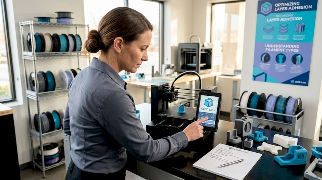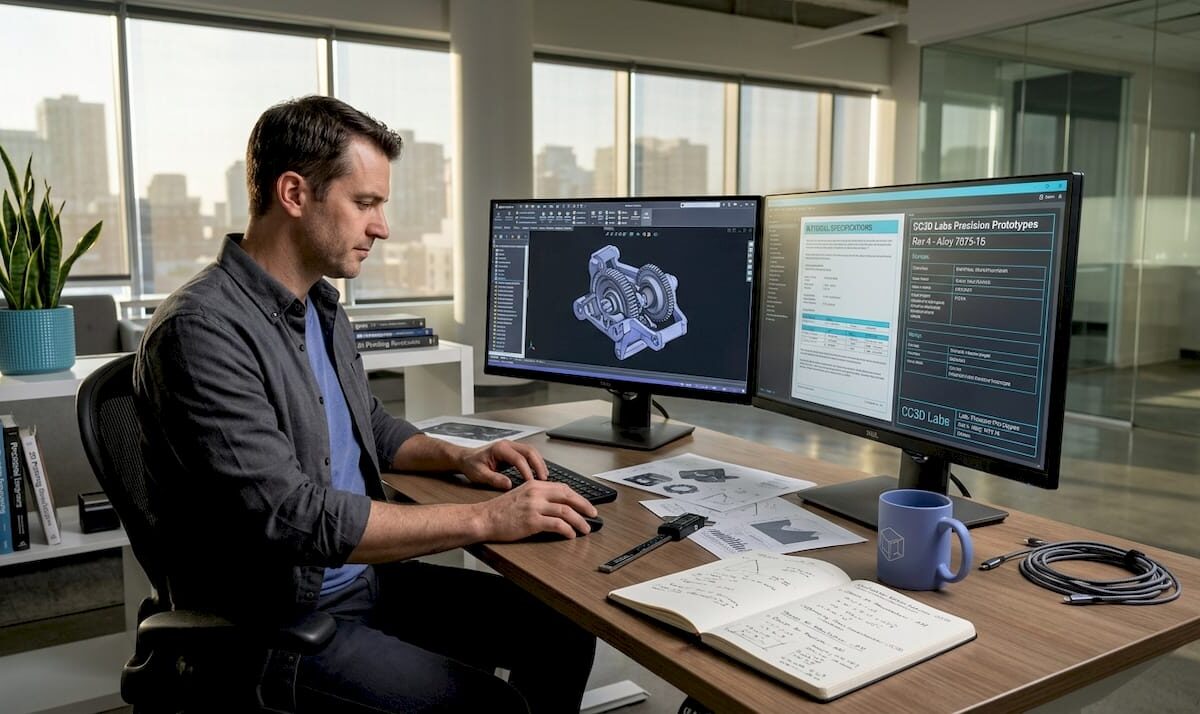
Engineer designing 3D printed part at desk

Functional Parts Printing Guide for Engineers in 2026


TL;DR:

  • Producing 3D printed parts that truly perform under load and environmental conditions requires careful design, process alignment, and post-processing.
  • Implementing discipline from the initial design through validation ensures functional integrity and cost-effectiveness in additive manufacturing.

Getting a prototype in hand fast means nothing if it fractures under the first load test. This functional parts printing guide addresses the real challenge product engineers face: producing 3D printed parts that actually perform under mechanical, thermal, or assembly conditions — not just parts that look like the final design. Additive manufacturing, the recognized industry term for what most call 3D printing, has matured enough to support genuine functional validation and low-volume production. But only if you approach it with the same discipline you’d apply to machined components. This guide walks you through design, process setup, post-processing, and manufacturing transitions.

Table of Contents

Key takeaways

Point Details
Design for function first Plan wall thickness, orientation, and geometry around load paths before sending any file to a printer.
Match process to validation goal Choose FDM, SLS, or SLA based on what the test must prove, not what equipment is available.
Post-processing is not optional Skipping cleaning, curing, or inspection steps directly undermines mechanical performance and repeatability.
Know your volume breakpoint 3D printing is cost-effective under roughly 50 units; beyond that, CNC or injection molding typically wins on economics.
Document every iteration Consistent parameter records let you reproduce a successful print and diagnose failures without guessing.

Your functional parts printing guide starts with design

Most print failures are decided before the first layer is deposited. The design stage is where functional parts are won or lost, and the engineers who understand that produce better parts faster than those who treat design-for-additive as an afterthought.

Start with a clear mechanical requirements brief. List the expected loads, operating temperature range, required tolerances, and assembly interfaces. Then map failure modes. A housing that must survive drop impacts has entirely different geometry requirements than a fluid-flow test fixture. Functional prototyping methods must match the validation need, and that alignment begins with understanding what a failed test actually tells you.

Layer orientation drives strength more than material choice does. Layer orientation in additive manufacturing critically impacts anisotropic strength and must be planned around principal loading directions. An FDM part loaded perpendicular to its layer lines will fail at a fraction of the load it could handle if printed with layers running parallel to the stress. Model this in your CAD setup before slicing.

Key design principles for functional parts:

  • Replace sharp internal corners with fillets of at least 0.5mm to reduce stress concentration and improve layer-to-layer adhesion at transitions
  • Keep minimum wall thickness above 1.2mm for FDM and 0.8mm for SLA to avoid fragile shell sections
  • Align critical interfaces, such as press-fit bores and threaded inserts, with the print’s strongest axis
  • Use integrated functional features like living hinges and printed bearings rather than designing parts that require complex post-assembly
  • Apply DFM principles from concept: applying DFM early accelerates timelines by 25 to 60 percent and can yield up to 40 percent cost savings

Pro Tip: Maintain separate CAD versions for your printed prototype and any future machined or cast production version. The geometric requirements conflict enough that a single model leads to compromises in both.

Step-by-step process for printing functional prototypes

Once your design is optimized, the printing workflow itself has to be deliberate. Skipping validation steps at any stage compounds errors and wastes print time.

  1. Validate the mesh file. Run your STL or 3MF file through a mesh repair tool before slicing. Check for non-manifold edges, inverted normals, and wall thickness violations. A five-minute file check prevents a ten-hour failed print.
  2. Select the right printing technology. FDM works well for structural iteration in engineering thermoplastics like PETG, ASA, or Nylon. SLA delivers tighter dimensional accuracy for fluid interfaces and fine geometry. SLS produces isotropic parts without support structures, which matters for complex functional geometries. For prototypes under 50 units, additive manufacturing eliminates tooling costs entirely and can deliver small polymer parts in 4 to 12 hours. Refer to the right printing type guide when choosing between technologies for a specific functional requirement.
  3. Set parameters for strength, not speed. Increase infill to at least 40 percent for load-bearing parts. Use rectilinear or gyroid infill patterns over grid, which stress concentrates at nodes. Reduce print speed by 20 to 30 percent for the perimeter walls where surface finish directly affects friction fits and sealing faces.
  4. Optimize support placement. Overhang angles beyond 45 degrees require support, but support removal always risks surface damage. Reorient parts to minimize support contact on functional surfaces. Where support is unavoidable, use soluble support material or a low interface density.
  5. Iterate with intention. Track each parameter change against a specific performance hypothesis. 3D printing enables multiple design cycles in the time that one CNC prototype would require, but only if each cycle tests a defined variable.

Pro Tip: For Nylon and other hygroscopic materials, dry filament in an oven at 65°C for four hours before printing. Moisture in the filament creates porosity that destroys inter-layer adhesion in functional parts.

Read the filament prototyping guide for a deeper breakdown of material-specific settings and how they affect mechanical output.

Post-processing and quality control for functional parts

Printing is not the last step. Post-processing for 3D printed parts — including cleaning, surface finishing, and inspection — is vital to ensuring functional performance and repeatability. Incomplete post-processing can directly undermine mechanical properties.

The specific workflow depends on your printing technology:

  • FDM parts: Remove support structures carefully using flush cutters and files. Sand critical mating surfaces with 220 to 400 grit sandpaper, progressing through grits to avoid micro-scratches that act as crack initiation points. Apply thin layers of cyanoacrylate to sealing surfaces for improved surface density.
  • SLA parts: Wash in isopropyl alcohol immediately after printing to remove uncured resin. Post-cure under UV light to complete the polymer crosslinking; under-cured SLA parts are brittle and will test poorly. Measure cure time against the resin manufacturer’s specification, not by appearance.
  • SLS parts: Media blast to remove powder and improve surface finish. The naturally porous surface benefits from infiltration with epoxy or urethane when the part must seal against fluid or gas.

Dimensional inspection is where many teams cut corners and pay for it later. Use calipers for general tolerances, but for critical interfaces, use a coordinate measuring approach to verify feature locations against your CAD nominal. Document every inspection result alongside the print parameters. This record becomes the foundation for process repeatability when you need to reproduce a successful part weeks later.

Pro Tip: If a functional part shows warping or delamination, do not simply reprint. First diagnose the root cause — bed adhesion, cooling rate, or material moisture — or you will repeat the failure.
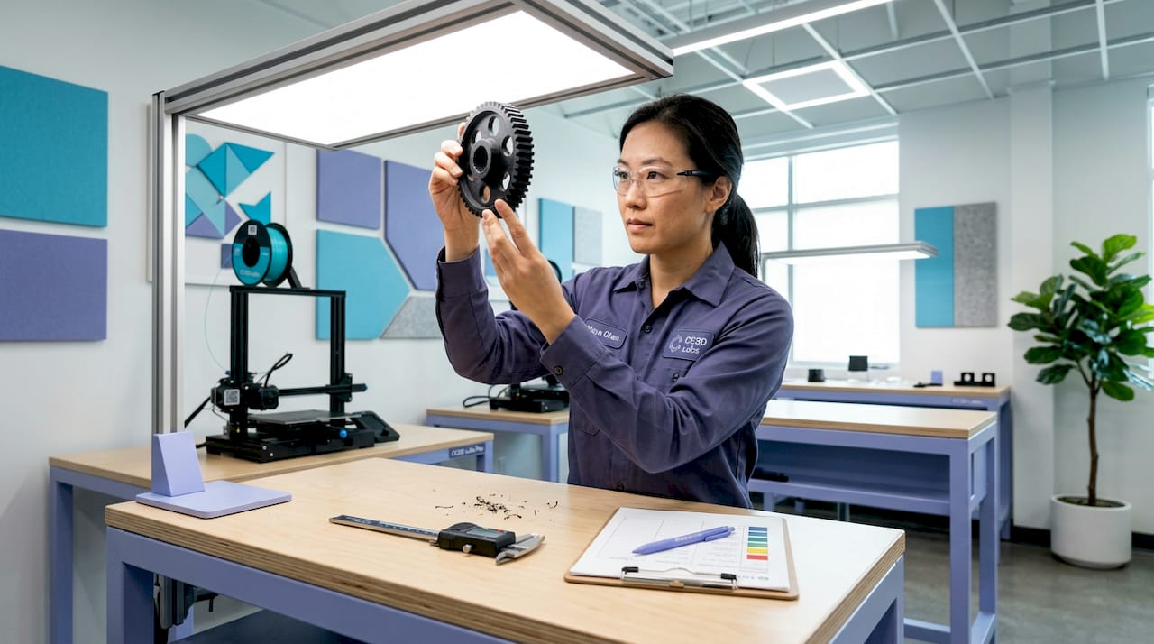
Technician checks 3D printed part for defects

Choosing between printing and traditional manufacturing

Understanding where additive manufacturing fits in your product lifecycle prevents misallocated budget and inconclusive test results. The manufacturing method must align with what you are trying to prove at each project stage.
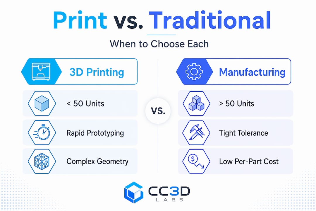
Infographic comparing 3D printing and manufacturing use cases

Stage Best method Reason
Concept validation FDM / SLA Fast geometry confirmation, low cost, accepts frequent changes
Functional prototype testing SLS / SLA / FDM with engineering resins Isotropic properties or tight tolerances for credible mechanical data
Bridge production (under 50 units) SLS or metal printing No tooling investment, delivery in days
Low-to-mid volume (50 to 500 units) CNC machining Tight tolerances, consistent material properties, lower unit cost
High volume (500+ units) Injection molding Lowest unit cost, highest repeatability

3D printing becomes cost-prohibitive for runs beyond low-volume production. At that point, injection molding and CNC machining reduce unit costs substantially. The mistake many teams make is staying with 3D printing past the point where it makes economic sense, or switching to machining before the design has stabilized, which forces expensive tooling changes.

Hybrid workflows solve much of this problem. Print the structural prototype, machine the critical mating surfaces to tolerance after printing, and validate the combination. This approach captures the speed of additive and the precision of subtractive manufacturing without fully committing to either until the design is frozen. The manufacturing-grade 3D printing guide covers the specific parameter requirements when parts need to meet production-level standards.

Many engineers also underestimate how much mismatching prototyping methods to validation goals costs in wasted test cycles. A printed part that behaves differently from the production material under load does not invalidate the design. It invalidates the test.

My take on functional printing after years in the field

I’ve watched engineers with genuinely strong mechanical instincts make avoidable mistakes with additive manufacturing, and nearly all of them stem from the same place: treating 3D printing as a faster version of machining rather than as its own discipline.

The anisotropy issue alone has cost teams weeks. I’ve seen a structurally sound bracket design fail at 30 percent of its calculated load simply because nobody modeled the print orientation against the load direction. The fix took ten minutes in the slicer. The realization cost three weeks of iteration.

What I’ve found is that upfront process discipline, which means designing for the print, not the part, pays back faster than any other investment in a project. Teams that document their parameter decisions from iteration one spend half the time troubleshooting as those who treat each print as a fresh experiment.

My strongest recommendation: adopt hybrid manufacturing thinking from day one. Don’t wait until you hit a production volume to start thinking about how your additive prototype relates to your machined or molded production part. The design choices you make for printability will often conflict with the choices that make a part manufacturable at scale. Knowing that early changes the conversation and keeps the project on schedule.

Speed is seductive in prototyping. But a well-planned slower iteration beats three fast ones that tell you nothing.

— Justin

How Cc3dlabs can support your functional parts projects

https://cc3dlabs.com

Cc3dlabs, based near Philadelphia, works directly with engineers and product developers on exactly this kind of challenge: functional parts that have to perform, not just exist. Their professional 3D printing services cover FDM with engineering-grade filaments, multi-color printing, CAD support, and professional handheld 3D scanning (accuracy to ~0.1 mm) for post-print inspection. Whether you need a single functional prototype or a low-volume production run of 30 parts, Cc3dlabs offers free online estimates, design feedback, and fast local turnaround with international shipping. If your team needs a reliable partner to take a validated design from prototype through bridge production, reach out to Cc3dlabs for a project consultation.

FAQ

What materials work best for functional 3D printed parts?

PETG, Nylon, ASA, and PEEK are the most widely used engineering filaments for functional FDM parts, selected based on temperature resistance, chemical exposure, and mechanical load requirements. For SLA, engineering resins rated for ABS-like or high-temp behavior outperform standard resins in functional testing.

How does print orientation affect part strength?

Layer orientation controls the direction of anisotropy in printed parts, meaning a part loaded perpendicular to its layer lines will fail significantly earlier than one printed with layers parallel to the principal stress. Always orient parts so critical load paths run along the layer direction, not across it.

When should I switch from 3D printing to CNC machining?

3D printing is cost-effective for prototypes and small batches under roughly 50 units. Beyond that threshold, or when tolerances tighter than ±0.1mm are required across multiple features, CNC machining delivers better economics and more reliable dimensional accuracy.

What causes warping in functional parts and how do I fix it?

Warping results from differential thermal contraction during cooling, most commonly in large, flat FDM parts printed in ABS or Nylon. Fix it by using a heated enclosure, increasing bed temperature, adding a brim, and drying filament thoroughly before printing.

How do I verify that a printed functional part meets my design specifications?

Use calipers for general dimension checks and a coordinate measuring device or 3D scan for critical feature verification. Document each inspection result against the print parameters so you can reproduce passing parts and trace the cause of any out-of-tolerance results.
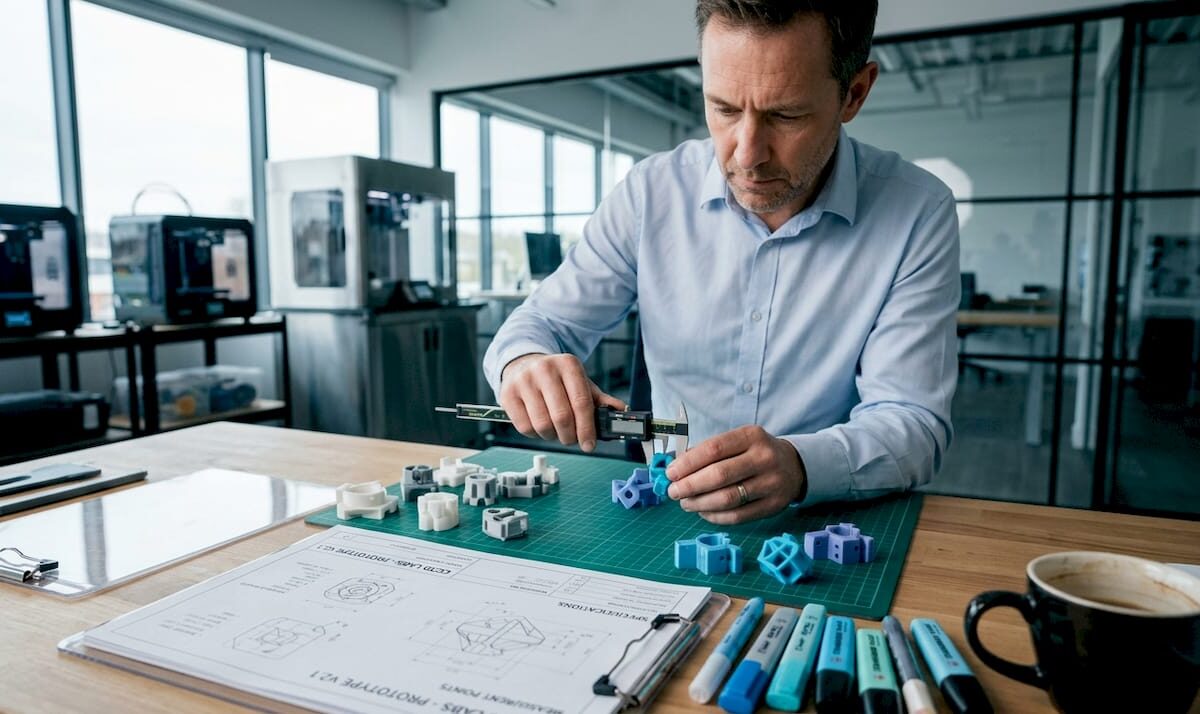
Engineer inspecting 3D printed parts at bench

Qualities of Precision 3D Parts Every Engineer Should Know


TL;DR:

  • Achieving true precision in 3D printing involves controlling tolerances, surface finish, and internal integrity throughout the entire process.
  • Effective collaboration between designers and manufacturers, along with comprehensive inspection methods like CT scanning, ensures consistent, high-quality parts ready for critical applications.

Understanding the qualities of precision 3D parts separates engineers who get functional assemblies right the first time from those who spend weeks chasing tolerance failures. Precision in additive manufacturing is not simply “the printer is accurate.” It covers dimensional tolerance control, surface integrity, material behavior, process repeatability, and post-processing effects working together. This article breaks down the specific technical characteristics that define a truly precise 3D printed part, how different technologies compare, and what process controls actually move the needle for engineers and product developers in 2026.

Table of Contents

Key takeaways

Point Details
Tolerance defines function High-precision parts target ±0.05 mm to ±0.1 mm, but the full print-to-finish process determines final dimensional accuracy.
Technology choice matters SLA and DLP deliver the tightest tolerances; SLS and DMLS trade some precision for structural complexity.
Precision includes the interior CT scanning per ASTM standards reveals internal defects that surface measurement alone cannot catch.
DfAM reduces tolerance failures Design for Additive Manufacturing strategies like strategic orientation and fillets prevent warping and dimensional drift.
Post-processing is part of precision Shrinkage, curing, and finishing steps materially affect final dimensions and must be controlled, not assumed.

1. The core qualities of precision 3D parts defined

Most engineers use “precision” as a catch-all, but manufacturing distinguishes three separate concepts: accuracy, precision, and repeatability. Accuracy means the part hits its nominal dimension. Precision means it hits the same dimension consistently across multiple prints. Repeatability means the entire process produces identical results across batches, machines, and operators.

High-precision printed parts commonly target dimensional tolerances of ±0.05 mm to ±0.1 mm, with layer heights as thin as 10 to 25 µm and surface roughness (Ra) values low enough to meet optical and medical standards. Industrial-grade systems achieve this through advanced process controls and active compensation for material shrinkage and thermal effects.

  • Dimensional tolerance: The allowable deviation from nominal geometry, typically expressed as ±X mm
  • Surface roughness (Ra): Average surface deviation in micrometers, directly affecting fit, friction, and sealing
  • Repeatability: Part-to-part consistency across a production run, not just a single successful print
  • Layer adhesion integrity: Uniform bonding between layers that prevents delamination under load
  • Build orientation effect: How the angle of a part on the build plate impacts anisotropic strength and dimensional accuracy

Pro Tip: When specifying tolerances for a printed part, always call out which surfaces are functional and which are cosmetic. Applying ±0.05 mm across an entire part inflates cost with no engineering benefit.

2. Tight dimensional tolerances and their effect on fit and function

Dimensional tolerance is the quality that most directly determines whether a part works in an assembly. A shaft that is 0.15 mm oversized will not seat in its bearing. A snap-fit feature that is 0.2 mm too thin will fail after three cycles.

For functional moving parts, engineered clearances of 0.2 to 0.4 mm are required in FDM to prevent fusion between adjacent surfaces during printing and enable proper articulation. This is not a flaw of the process. It is a designed-in reality that engineers must account for during modeling.

The important distinction is between as-printed tolerance and final tolerance. Shrinkage, curing, and finishing steps can materially alter final dimensional accuracy. A part that measures within spec on the build plate may drift outside tolerance after thermal post-processing. Treating the full workflow as a single controlled capability, not just the print stage, is what separates production-ready precision from prototype luck.

3. Consistent surface finish and low roughness metrics

Surface finish affects more than aesthetics. It governs sealing performance, friction in moving assemblies, fatigue life under cyclic loading, and adhesion in bonded joints. Ra values below 1.6 µm are achievable with resin-based processes; industrial FDM typically produces Ra values between 6 and 25 µm before post-processing.

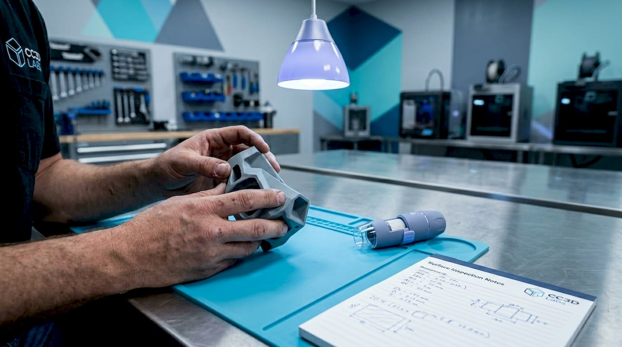
Hands inspecting 3D printed surface texture

Post-processing methods change this significantly. Vapor smoothing reduces surface roughness in FDM parts by 70 to 90 percent in some cases. Bead blasting improves surface uniformity in SLS parts while reducing friction in joints. CNC machining of critical surfaces brings any printed part to sub-micron roughness when required.

The practical implication: specify surface finish by Ra value on your technical drawing, not by process. Let the manufacturer select the combination of printing and finishing that hits the number. You get better results and more flexibility in sourcing.

4. Feature resolution and minimum wall thickness

Fine features are where many additive processes fail quietly. A design that looks correct in CAD can lose detail, round edges, or merge adjacent features when translated into physical layers.

Minimum wall thickness for FDM typically runs 0.8 to 1.2 mm for structural reliability. SLA and DLP push that down to 0.3 to 0.5 mm. DMLS for metal parts holds around 0.3 to 0.4 mm. These numbers change with build orientation: walls parallel to the Z axis are generally thinner and more fragile than walls built horizontally.

The characteristics of high-quality 3D models include geometry that accounts for these physical limits. Features that are thinner than the process minimum either print poorly or not at all. Reviewing your model against the capabilities of your chosen process before sending it to print saves significant rework time.

5. Volumetric integrity verified through CT scanning

External dimensional inspection only tells part of the story. Internal porosity, incomplete fusion, entrapped powder, and micro-cracks are invisible to calipers and CMMs. These defects are particularly consequential in aerospace, medical, and pressure-vessel applications where internal flaws cause catastrophic failure.

CT inspection for additive manufacturing provides volumetric nondestructive testing for internal defects and dimensional verification beyond surface measurement, guided by ASTM standards E3166 and F3624. It reveals porosity and lack-of-fusion defects that are essential to catch in aerospace and medical quality assurance workflows.

This is not just an inspection technique. It is a process feedback tool. When CT results show consistent porosity at a specific layer height, that points directly to a process parameter issue. Catching it early across a batch prevents an entire production run from failing qualification.

Pro Tip: For certification-bound parts, request a CT scan report as part of your first article inspection package. It closes the loop between dimensional compliance and internal integrity in a single document.

6. Material homogeneity and post-processing effects

Material behavior during and after printing directly shapes the final precision of a part. Polymers shrink as they cool. Resins shrink during UV curing. Metals contract during sintering and heat treatment. Each process has a characteristic shrinkage profile that must be compensated in the pre-print CAD model.

Tight tolerances in metal additive manufacturing require thermal control, pre-compensated CAD models, and rigorous post-print inspection to avoid dimensional failures in aerospace and medical implants. That compensation is not a one-time correction. It is a machine-specific, material-specific, geometry-specific calibration that changes when any of those variables change.

Material homogeneity also matters for anisotropic strength. FDM parts are measurably weaker in the Z axis than in XY due to layer-to-layer bonding mechanics. Knowing this allows you to orient critical load paths in the XY plane at the design stage, rather than discovering the failure mode during testing.

7. Comparison of printing technologies by precision capability

Different processes achieve different tolerance levels, and selecting the right one for your precision requirement is a core decision. Here is a direct comparison of the major technologies:

Technology Typical tolerance Min feature size Best use cases
SLA ±0.05 mm 0.3 mm Dental, optics, microfluidics
DLP ±0.05 mm 0.3 mm Jewelry, hearing aids, small complex parts
PolyJet ±0.05 mm 0.2 mm Multi-material prototypes, overmold simulation
SLS (polymer) ±0.1 to 0.2 mm 0.5 mm Functional parts, complex geometry, no supports
DMLS (metal) ±0.1 to 0.2 mm 0.3 mm Aerospace, medical implants, tooling
Industrial FDM ±0.1 to 0.2 mm 0.8 mm Structural prototypes, jigs, fixtures

Resin-based technologies like SLA and DLP offer tolerances around ±0.05 mm with fine feature resolution, making them ideal for dental and microfluidic applications. Powder-based processes like SLS and DMLS achieve slightly broader tolerances but excel in functional structural parts with complex internal geometry.

Choosing the right process means matching tolerance capability to the function of the part. For a consumer product prototype, industrial FDM may be entirely sufficient. For a flight-critical bracket, DMLS with CT verification is the correct choice. Review the full technology comparison guide before committing to a process for a new program.

8. Best practices and process controls for achieving precision

Achieving precision in additive manufacturing requires controlling inputs at every stage of the workflow:

  1. Apply DfAM principles from the start. Design for Additive Manufacturing strategies such as adding fillets, minimizing large flat surfaces, and orienting parts on the XY plane reduce warping and dimensional drift before the printer ever starts.
  2. Use software compensation for shrinkage. Pre-scale the CAD model based on known material shrinkage coefficients for the specific machine and material combination. This is especially critical in metal DMLS and photopolymer SLA.
  3. Control the build environment. Temperature, humidity, and machine calibration directly affect dimensional output. Well-maintained machines with calibrated build plates produce measurably tighter results than machines running with drift.
  4. Implement CT inspection for functional parts. CT per ASTM standards ensures repeatability and certification readiness beyond typical surface metrology.
  5. Document traceability per AS9102 Rev C. AS9102 Rev C standards establish requirements for characteristic accountability in first article inspection, including nominal values, tolerances, GD&T callouts, and verification outcomes for each design characteristic.
  6. Plan post-processing as a controlled step. Vapor smoothing, reaming, bead blasting, and CNC finishing are not afterthoughts. Each one affects final dimensions. Budget tolerances accordingly.

Pro Tip: Build a tolerance stack-up analysis before finalizing your 3D printing process. Account for the as-printed tolerance, expected shrinkage, and the effect of any finishing steps. That stack-up tells you whether your process is capable before you print a single part.

Understanding tolerances in 3D printing at the engineering level is the single most effective way to close the gap between what your CAD model shows and what you hold in your hand.

My honest take on precision in additive manufacturing

I’ve worked with enough engineers and product developers to know that the word “precision” gets used loosely. A lot of projects arrive at the printer with tight tolerances applied uniformly across the entire part drawing, with no post-processing plan and no inspection defined. Then everyone is surprised when the part doesn’t fit.

In my experience, the biggest precision failures don’t come from the printing process itself. They come from treating the print as the final step. Shrinkage, curing, and finishing steps materially affect final accuracy, and ignoring that reality costs time and money on every program.

What I’ve also seen is that CT scanning changes the conversation entirely for functional parts. CT inspection reveals internal defects that surface checks miss completely, and in aerospace and medical programs, that is the difference between a part that certifies and one that doesn’t.

My honest recommendation: get your designer and your manufacturer talking at the start of the project, not after first print failure. The best precision outcomes I’ve seen come from that collaboration. The worst come from throwing a completed drawing over the wall and expecting the printer to sort it out.

— Justin

How Cc3dlabs helps you achieve precision in every part

When precision is not optional, the process behind the print matters as much as the machine. Cc3dlabs brings together advanced FDM printing, professional handheld 3D scanning (accuracy to ~0.1 mm), and design support to help engineers and manufacturers hit their tolerance and quality targets from the first production run.

https://cc3dlabs.com

Whether you need a single prototype validated against your CAD model or a batch of functional parts with documented first article inspection, Cc3dlabs provides the precision 3D printing services and inspection capabilities to back it up. Their team can assist with material selection, DfAM reviews, post-processing planning, and 3D scanning verification to confirm dimensional compliance before anything ships. From concept validation to production-ready components, Cc3dlabs delivers the technical depth that precision programs demand.

Get a free online estimate and find out how Cc3dlabs can support your next precision project.

FAQ

What tolerance is considered precision in 3D printing?

High-precision 3D printed parts target dimensional tolerances of ±0.05 mm to ±0.1 mm, depending on the technology. SLA and DLP processes achieve the tighter end of that range, while FDM and SLS typically operate toward ±0.1 to 0.2 mm without post-processing.

How do I verify precision in a 3D printed part?

Surface metrology with calipers or a CMM covers external dimensions, but CT scanning per ASTM standards E3166 and F3624 is required to verify internal integrity and catch porosity or fusion defects invisible to surface measurement.

Does post-processing affect final dimensional accuracy?

Yes. Shrinkage, curing, vapor smoothing, and CNC finishing all alter final part dimensions. The full print-to-finish workflow must be treated as a single controlled capability, not isolated stages.

Which 3D printing technology is most precise?

Resin-based technologies, specifically SLA, DLP, and PolyJet, deliver the tightest tolerances around ±0.05 mm and are best for fine-feature applications. DMLS leads in metal precision for structural and certification-critical components.

What is DfAM and why does it matter for precision?

Design for Additive Manufacturing (DfAM) is the practice of adapting geometry to suit additive process constraints. Strategic orientation, fillets, and support design reduce warping and dimensional drift, directly improving the precision of the printed part without changing the machine or material.

Engineer choosing filament for 3D printing in lab

Why Choose Filament for Engineering Parts: 2026 Guide


TL;DR:

  • Choosing the correct filament is essential for ensuring the performance, durability, and environmental resistance of engineering parts, preventing costly failures.
  • Selecting materials like PETG, nylon, or carbon fiber composites depends on mechanical, thermal, and environmental requirements, with proper process control and supplier reliability being critical for success.

Choosing the wrong filament for an engineering part is not just a performance issue. It can mean a failed prototype, a recalled product, or thousands of dollars in avoidable rework. The question of why choose filament for engineering parts goes deeper than picking the strongest material on the shelf. Engineering-grade filaments are selected for functional performance first, not ease of print, and the spectrum of available materials now spans simple PETG all the way to carbon fiber reinforced composites. Understanding that range, and knowing where each material fits, is what separates parts that work from parts that just look like they work.

Table of Contents

Key takeaways

Point Details
Filament choice drives part performance Mechanical properties like tensile strength and heat deflection temperature directly determine whether a part survives in service.
Environment shapes material selection UV, chemical exposure, and moisture can degrade the wrong filament quickly, making environmental fit as critical as strength.
Printability affects real-world outcomes A material with excellent specs on paper fails if your process cannot reliably print it without warping or delamination.
Cost-effectiveness goes beyond unit price Higher-cost filaments often reduce failure rates and iteration cycles, lowering total project cost over time.
Match material to application, not ego Over-engineering with premium filaments wastes budget. Selecting a fit-for-purpose material is a professional decision, not a compromise.

Why choose filament for engineering parts

Not all 3D printing filaments are created equal, and the engineering world proves that point daily. Professional material selection is a deliberate inquiry that balances load requirements, environmental conditions, and processing demands rather than simply reaching for whatever is labeled “strong.”

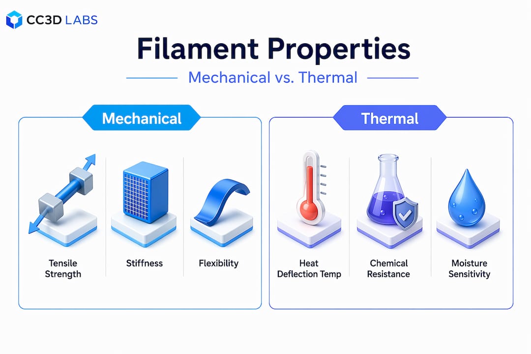
The core filament properties that determine suitability for functional parts fall into two categories: mechanical and thermal.

Infographic comparing mechanical and thermal filament properties

Mechanical properties that matter

Tensile strength tells you how much pulling force a part can take before it snaps. Stiffness, measured as elastic modulus, tells you how much it flexes under load. Toughness combines both into a measure of how much energy a part absorbs before fracturing. For engineers, toughness is often more useful than raw strength, especially for parts subject to impact or vibration.

Here is how common engineering filaments compare on key mechanical and thermal benchmarks:

Filament Tensile Strength (MPa) Heat Deflection Temp (°C) Best Use Case
PETG 50 80 Prototypes, housings
ABS 40 98 Interior structural parts
ASA 45 100 Outdoor structural parts
Nylon (PA12) 55 110 Wear parts, gears
Polycarbonate 65 130 High-load brackets
CF Reinforced 80+ 130+ Structural frames, jigs

Carbon fiber reinforced filaments deliver 2 to 3 times higher stiffness and heat deflection temperatures around 130°C compared to unfilled plastics. That gap matters when you are building jigs, fixtures, or any part that must hold dimensional tolerance under temperature cycling.

Thermal properties deserve equal attention. Heat deflection temperature (HDT) is the point at which a part begins to deform under load at elevated temperatures. Glass transition temperature (Tg) marks where the polymer structure softens. A housing printed in PETG with an 80°C HDT will warp inside a vehicle dashboard or near industrial heat sources. That failure is not a print defect. It is a material mismatch.

Technician testing 3D part heat resistance

Pro Tip: When specifying filaments for load-bearing parts, request the material’s datasheet from your supplier. Published HDT values tested under 0.45 MPa load are more conservative and more accurate for engineering use than values tested under 1.82 MPa.

Environmental resistance and filament choice

Knowing how a part performs in a lab is only half the picture. The environment where it will actually live determines whether a perfectly printed part survives a season outdoors, a chemical wash, or a humid warehouse.

The key environmental factors that should drive your filament selection are:

  • UV and weather resistance: ABS degrades noticeably under prolonged UV exposure. ASA filament provides superior UV and weather resistance, making it the go-to choice for outdoor parts that need to last years without significant degradation. It shares ABS’s strength and heat resistance while adding meaningful sunlight stability.
  • Chemical resistance: Nylon and polycarbonate can absorb certain solvents and degrade in acidic environments. PETG offers reasonable chemical resistance for many industrial cleaning agents. For aggressive chemical environments, check material-specific resistance charts before committing to a filament, or reference industrial pipe material guides to see how comparable polymers hold up in practice.
  • Moisture absorption: Nylon is highly hygroscopic. Uncontrolled moisture absorption does not just cause print failures. It directly degrades the mechanical properties of finished parts, reducing tensile strength and increasing brittleness over time. Parts printed from wet nylon are structurally compromised before they leave the printer.

Pro Tip: Dry nylon filament at 70 to 80°C for at least four hours before printing, and store it in a sealed container with desiccant. If you are running production quantities, an inline drying system attached to your printer feed is worth the investment.

For your outdoor parts selection, the Cc3dlabs guide covering outdoor-durable filaments breaks down the top material choices with real-world context.

Printability challenges with engineering filaments

Strong on paper does not mean easy to print. Engineering-grade filaments introduce processing requirements that general-purpose PLA users never encounter, and understanding those requirements before you start is how you avoid wasted prints and failed parts.

Here is the printability spectrum from accessible to highly specialized:

  1. PETG prints cleanly on most desktop FDM machines with a 230 to 250°C nozzle and a 70 to 85°C bed. Warping is minimal, and layer adhesion is reliable. It is the most accessible entry point for durable engineering parts.
  2. ABS and ASA require a heated enclosure to prevent warping, particularly on large footprint parts. Bed temperatures in the 100 to 110°C range and a consistent ambient temperature around 45 to 50°C are necessary for dimensional stability.
  3. Nylon needs a dry filament environment, high bed adhesion (PEI or garolite surfaces work well), and nozzle temperatures around 240 to 270°C depending on grade. Without proper drying, expect stringing, poor layer fusion, and degraded mechanical properties.
  4. Polycarbonate requires nozzle temperatures of 270 to 300°C and is highly prone to warping without an enclosed, heated chamber. It also absorbs moisture aggressively, so storage protocol matters.
  5. Carbon fiber composites need hardened steel or ruby-tipped nozzles. Standard brass nozzles wear out within a few hundred grams of CF-reinforced material. Carbon fiber reinforcement improves dimensional stability by locking the polymer matrix and reducing warping during cooling, which is a major advantage for complex or large parts.
  6. PEEK occupies its own category entirely. PEEK filaments require industrial-grade printers with nozzle temperatures between 360 and 450°C and bed temperatures from 120 to 160°C. Its use is only justified in extreme heat and chemical environments where no alternative material will hold up.

Bringing high-temperature filament capability in-house changes iteration economics significantly, shortening design-test-iterate cycles and reducing time-to-market for engineering teams working on complex assemblies.

Pro Tip: Before scaling a material to production volumes, run a print qualification test: print the same geometry in three separate batches from three separate spools. Variation between batches reveals supplier inconsistency before it becomes a production problem.

Cost-benefit analysis for filament selection

The sticker price of a filament spool is the least useful number in your cost analysis. What actually drives cost in filament-based engineering parts is the total cost of ownership: failed prints, post-processing time, rework rates, and iteration cycles.

Consider this comparison:

Filament Approx. Cost per kg Failure Rate (Est.) Best Total Cost Scenario
PETG $25 to $40 Low High-volume functional prototypes
Nylon PA12 $50 to $80 Medium (if wet) Gears, wear parts
Polycarbonate $60 to $100 Medium-High Structural load applications
CF Nylon $80 to $150 Low (with right setup) Stiff structural components
PEEK $200 to $400+ High without industrial hardware Extreme environments only

PETG is a pragmatic starting material for durable parts not exposed to extreme heat or chemicals. It combines printability with reasonable toughness and is widely available from consistent suppliers. For many functional parts, PETG delivers everything you need at a fraction of the cost of exotic materials.

The trap engineers fall into is over-engineering the material when the design is the actual problem. A polycarbonate bracket printed with poor layer adhesion will outperform nothing. A well-designed PETG bracket printed with optimal parameters will outlast a badly printed polycarbonate one every time.

Pro Tip: Before jumping to premium filaments, audit your print parameters and part design first. Most real-world failures in functional filament parts come from inadequate wall thickness, poor infill strategy, or moisture-degraded material, not from choosing the wrong polymer family.

Real-world applications across filament types

Theory becomes useful when you can connect it to specific parts solving specific problems.

  • Outdoor enclosures and mounting brackets: ASA is the clear choice. Engineering teams building antenna mounts, sensor housings, or outdoor junction boxes routinely use ASA to get ABS-level toughness without the UV degradation risk. Parts produced with ASA maintain structural integrity and color stability after years of direct sun exposure.
  • Wear-resistant sliding parts and bearings: The Igus Iglidur i190PF filament achieves wear rates 100 times lower than standard PETG, tested in a dedicated tribology laboratory against stainless steel. For lubrication-free bushings, guide rails, or any sliding contact application, this class of material changes what is achievable with FDM printing.
  • Structural prototypes and tooling jigs: Carbon fiber reinforced nylon or PETG delivers the stiffness needed for jigs, fixtures, and assembly aids. The dimensional stability under temperature cycling makes CF composites far more reliable than unfilled materials for production floor tooling, where tolerances matter every shift.
  • Functional prototypes bridging to production: PETG and ABS occupy a productive middle ground for prototype engineering parts where you need real mechanical behavior data without committing to expensive materials or processes. They print predictably, iterate quickly, and are cheap enough to run multiple design variants in a single day.

My take on filament selection in the real world

I have seen engineering teams spend weeks debating whether to use carbon fiber reinforced nylon versus PEEK for a bracket that operates at room temperature with a 20-pound static load. That debate was not an engineering decision. It was anxiety wearing the costume of rigor.

In my experience, the biggest mistake engineers make when selecting filaments is conflating material prestige with material fitness. The best filament for your part is the one that meets your mechanical, thermal, and environmental requirements at the lowest total cost with the highest print reliability. Full stop.

What I have found actually separates strong filament workflows from weak ones is not the material choice. It is the testing discipline. Teams that run small print qualification batches before committing to a material, that document their failure modes, and that track print parameters across suppliers iterate faster and waste far less than teams that treat every print as one-off experimentation.

Supplier quality is also wildly underrated. The same nominal filament from two different manufacturers can produce measurably different mechanical outcomes. Diameter consistency, moisture control during shipping, and formulation stability vary more than most engineers expect. Finding a reliable supplier and sticking with them across a project is a real process advantage.

Finally, building your material knowledge through deliberate iteration beats reading datasheets alone. Print the same geometry in three materials. Load test them. Break them. The result will tell you more than any specification document.

— Justin

How Cc3dlabs supports your engineering parts workflow

Working with engineering-grade filaments in-house is a significant capital and process investment. Cc3dlabs offers a ready alternative for teams that need production-quality filament parts without building the infrastructure from scratch.

https://cc3dlabs.com

From functional prototypes in PETG and ASA to advanced composite prints for structural applications, Cc3dlabs handles the material selection, process optimization, and quality validation so your team can focus on design. Their 3D printing services cover everything from single prototype prints to batch production runs, with fast turnaround and material guidance built into the engagement. If your project involves complex geometries, tight tolerances, or high-performance filament requirements, their team near Philadelphia offers both local pickup and shipping, backed by a track record of print accuracy that engineering applications demand. You can also explore how 3D printing drives product innovation to see where filament-based manufacturing fits in the broader product development picture.

FAQ

What filament is best for functional engineering parts?

The best filament depends on your specific load, temperature, and environmental conditions. PETG suits most prototypes and housings, while nylon, polycarbonate, and carbon fiber composites are better for higher-stress or high-temperature applications.

Why use filament instead of other manufacturing methods?

Filament-based 3D printing offers rapid iteration, low tooling cost, and the ability to produce complex geometries without fixturing. It is especially effective in early-stage development when design changes are frequent and speed matters more than per-unit cost.

How does moisture affect engineering filament parts?

Hygroscopic filaments like nylon absorb moisture from the air, which degrades both print quality and finished part strength. Drying filament before use and storing it with desiccant are non-negotiable steps for reliable engineering outcomes.

Is PETG strong enough for load-bearing parts?

PETG handles moderate loads well, with a tensile strength around 50 MPa and an HDT of roughly 80°C. For parts exposed to higher temperatures or impact forces, upgrading to polycarbonate or a carbon fiber reinforced filament delivers meaningfully better performance.

When does it make sense to use PEEK filament?

PEEK is justified only when a part must survive extreme heat above 200°C or aggressive chemical environments where no other filament will hold up. Its processing demands and cost make it impractical for most standard engineering applications.

Engineer checking CAD model for optimization

The 3D Part Optimization Process for Engineers


TL;DR:

  • Engineers often overlook that proper part orientation, wall count, and design choices significantly improve strength and reduce support needs. Focusing on defining requirements before slicing ensures optimal geometry, load paths, and fit, minimizing material waste and print time. Validating mating interfaces with small test prints early can prevent costly reprints and streamline production.

Every engineer who has pulled a brittle, support-crusted print off the bed and thought “this should have worked” knows the real cost of skipping the 3d part optimization process. Poor orientation choices, default infill settings, and designs that weren’t built with additive manufacturing in mind waste filament, machine time, and development cycles. The good news: optimization isn’t guesswork. It’s a structured sequence of decisions that starts before you touch your slicer and ends only after you’ve validated the finished part. This guide walks you through that sequence, step by step.

Table of Contents

Key takeaways

Point Details
Start with requirements, not settings Define load paths, fit requirements, and production volume before opening your slicer.
Orientation beats infill for strength Aligning loads parallel to layer lines delivers more strength per gram than chasing high infill percentages.
Walls drive structural performance Increasing perimeter count from 2-3 to 4-6 can dramatically improve tensile strength with minimal added print time.
Design out supports early Chamfers, 45° self-supporting angles, and split-part strategies reduce material waste before printing begins.
Validate interfaces before full runs Printing only critical mating sections first catches fit issues early and protects your full material budget.

The 3D part optimization process starts with requirements

Before you adjust a single slicer setting, you need to know exactly what the part has to do. That sounds obvious, but a surprising number of optimization failures trace back to this step being skipped or treated superficially.

Ask four questions about every part you intend to print:

  • What loads will it carry? Tensile, compressive, torsional, impact? Each favors different orientation and material choices.
  • Does it mate with anything? Threads, press fits, snap fits, and sliding interfaces all require tight tolerance control that must be planned, not fixed in post-processing.
  • What’s the surface finish requirement? A cosmetic panel and a functional bracket can share the same material but need completely different layer heights and orientation decisions.
  • How many are you producing? A single prototype tolerates extra support and slower speeds. A batch of 200 functional parts does not.

Understanding these requirements directly shapes your decisions about part orientation, wall strategy, and infill density in every phase that follows. This integrated thinking across design and settings is what separates a deliberate optimization process from random trial and error.

Design for additive manufacturing principles apply here too. The most effective way to reduce supports is to design a part that doesn’t need them. Self-supporting geometry relies on keeping overhangs at or below 45° from vertical. Steeper angles require support material, which adds print time, wastes filament, and often leaves surface artifacts where the support contacted the part. When a feature requires a steep overhang, replacing it with a chamfer or splitting the part into two printable sections is almost always the better call. If you’re still developing your design workflow for manufacturing, locking in these principles at the modeling stage pays dividends across every print you run.

Pro Tip: When designing for batch production, model your split lines and chamfers as first-class design decisions, not afterthoughts. A five-minute geometry change during CAD can eliminate 40 minutes of support removal per unit.

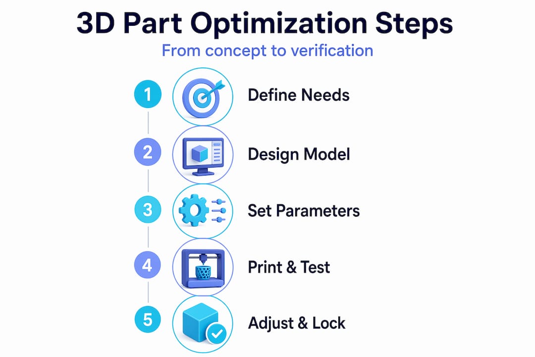
Infographic shows 3D part optimization workflow

Execution phase 1: print settings that actually build strength

Once your design respects the geometry rules, your slicer decisions determine whether the part meets its mechanical targets. The priority order here matters more than most engineers expect.

  1. Set orientation first. Parts are strongest along the X-Y plane because FDM materials exhibit layer anisotropy. Loads applied parallel to the layer plane are resisted by the full cross-section of the material. Loads applied perpendicular to layers rely on interlayer adhesion, which is the weakest bond in any FDM part. Orient the part so your primary load path runs parallel to the print bed whenever geometry allows.

  2. Choose nozzle size based on the part’s demands. A 0.4mm nozzle is a reasonable default, but it isn’t always right. Coarse structural parts with no fine features print faster and often stronger through a 0.6mm or 0.8mm nozzle because thicker extrusions bond better. Fine detail parts may need a 0.2mm nozzle. Choosing the wrong nozzle size means you’re either wasting time or sacrificing resolution you didn’t need to sacrifice.

  3. Prioritize walls over infill. This is where most engineers leave performance on the table. The priority decision-stack treats infill as supplemental, not structural. Infill supports the shell and transfers minor loads between walls. The walls themselves are load-bearing. Increasing perimeters from 2-3 to 4-6 can roughly double tensile strength with a fraction of the material cost that the same result would take with infill alone.

  4. Set layer height based on finish and throughput needs. Thinner layers improve surface quality and bonding at a cost of print time. Thicker layers print faster with slightly reduced Z-direction resolution. For structural parts where finish matters less, 0.2mm to 0.3mm is a solid range. For cosmetic or precision-fit surfaces, 0.1mm to 0.15mm is worth the added time.

  5. Dial in extrusion width and print speed together. Slightly over-extruding, setting extrusion width to 110-120% of nozzle diameter, improves layer bonding significantly. Pair that with conservative print speeds on outer walls and you get noticeably better surface finish without changing any material or hardware.

Pro Tip: Print your structural outer walls at 50-60% of your standard print speed. The inner walls and infill can run fast. The outer wall bond quality is what you’ll feel when you load the part.

If you want a consolidated view of how to reduce print costs without sacrificing mechanical performance, the relationship between wall count and infill is a good place to start.

Technician adjusting 3D printer in workspace

Execution phase 2: cutting supports and controlling fit

Support material is the single most expensive line item in many print budgets. You pay for it in filament, print time, and post-processing labor. The goal of the 3d printing optimization process at this stage is to minimize supports through geometry choices, not just slicer settings.

Key tactics to reduce support usage:

  • Replace any overhang steeper than 45° with a chamfer or stepped feature. Avoiding steep overhangs by design eliminates support needs at the source, which is far more material-efficient than generating supports and then removing them.
  • Split complex parts along natural support-free planes and bond or fasten them after printing. Two clean parts printed without support often outperform one supported print both mechanically and dimensionally.
  • Use slicer-level support controls as a last resort. Adjusting support overhang thresholds, interface layers, and Z-distance can reduce support volume and ease removal, but these are refinements to a design problem, not solutions.

Dimensional accuracy requires its own set of deliberate choices. Press fits and snap fits are particularly unforgiving. The standard approach of modeling a hole at nominal diameter and hoping the printer hits it rarely works without calibration. You need to run a calibration print for your specific material and temperature combination and capture your actual shrinkage coefficient before committing to tolerance-critical dimensions.

Pro Tip: For any part with a mating interface, print just the mating zone as a standalone test piece before running the full part. This fit-check approach uses under 3g of filament and roughly 30 minutes of print time to verify whether your tolerance assumptions are correct. It will save you full reprints.

Verification phase: test, adjust, and lock in

The 3d part optimization process does not end when the print finishes. A part that looks correct can still fail under load, exhibit unexpected surface artifacts, or refuse to mate with its counterpart. Verification is where you close that gap between what you designed and what the printer produced.

Follow this sequence for each new part or revised iteration:

  1. Print mating-section test pieces first. Fit-check prints isolate interface risk before you commit filament to the complete part.
  2. Evaluate the test piece dimensionally and functionally. Measure the actual feature dimensions against nominal. Check clearance, press force, snap engagement, or whatever the fit requirement specifies.
  3. Adjust tolerances in the model or slicer based on measured deviations. A 0.1mm to 0.2mm compensation is common for most FDM setups.
  4. Print the full part and evaluate strength and surface finish against your original functional requirements.
  5. Apply post-processing where the part still falls short. Annealing improves crystalline polymer strength. Epoxy coating improves surface hardness and moisture resistance. Sanding or chemical smoothing addresses cosmetic finish.

The table below summarizes what to adjust based on common verification failures:

Failure Mode Likely Cause Adjustment
Part fractures under load Weak layer adhesion or poor orientation Reorient load path, increase wall count, reduce print speed
Mating interface too tight Insufficient tolerance compensation Add 0.1-0.2mm clearance to hole features
Mating interface too loose Over-compensated tolerances Reduce clearance offset, recheck calibration
Poor surface finish on top layers Inadequate top layer count Increase top solid layers to 5-6
Warping or delamination Cooling or adhesion issues Reduce cooling fan speed, increase bed temperature

For low-volume production, this iteration cycle often runs two to three times before settings are locked. For scaled manufacturing runs, the investment in that early iteration cycle pays back in reduced scrap rates across every subsequent print.

What I’ve learned after watching engineers skip these steps

In my experience working on functional print projects, the single most consistent mistake I see product developers make is treating infill as the primary strength lever. They see a weak part and immediately bump infill from 20% to 60%. That consumes significantly more material and adds print time, but delivers far less strength improvement than simply adding two perimeter walls would have.

I’ve watched teams spend days reprinting support-heavy assemblies because the support geometry was never questioned at the design stage. A split-part strategy, something that would have taken an hour to model, would have eliminated the entire problem. The labor cost of support removal is rarely factored into part cost calculations, but it should be.

What I’ve found actually works is this: treat the first iteration of any new part as a learning print, not a production print. Print the mating sections, validate them, check your orientation against the load path, and then run the full part. That discipline, applied consistently, shortens development cycles more than any single settings trick. And early design validation before committing to full runs is the clearest signal I know that an engineering team is thinking about optimization the right way.

— Justin

Get expert support for your optimization workflow

https://cc3dlabs.com

If you’re working through a print optimization challenge and want experienced support behind your production process, Cc3dlabs is built for exactly that. Located near Philadelphia, Cc3dlabs provides precision printing and design support for product developers and engineers running prototypes, functional parts, and batch production orders. Their team handles orientation strategy, tolerance validation, and material selection as part of every project, so your parts arrive ready to function, not just ready to look at. From on-demand part production to professional handheld 3D scanning (accuracy to ~0.1 mm) for fit verification, Cc3dlabs offers the technical depth that turns optimization principles into consistent, repeatable results.

FAQ

What is the first step in the 3D part optimization process?

Define your functional requirements before touching your slicer. Understanding load paths, fit requirements, surface finish needs, and production volume shapes every orientation and settings decision that follows.

Does infill percentage affect part strength more than wall count?

No. Wall count dominates strength per unit of material in FDM parts. Increasing perimeters from 2-3 to 4-6 delivers significantly more tensile strength than equivalent infill increases, with less added filament.

How do I reduce support material when optimizing printed parts?

Design out supports by keeping overhangs at or below 45° and using chamfers or split-part strategies in your CAD model. Support avoidance by design is consistently more material-efficient than generating and removing supports after printing.

How should I validate fit before committing to a full print run?

Use your slicer to isolate and print only the mating-interface section of the part first. These fit-check test pieces use minimal filament and print quickly, letting you verify tolerance accuracy before running the complete part.

Why does part orientation matter so much in 3D printing optimization?

FDM parts are anisotropic. Strength along the X-Y plane is significantly higher than across layer boundaries. Orienting the part so primary loads run parallel to layers is one of the highest-return decisions in the entire optimization process.