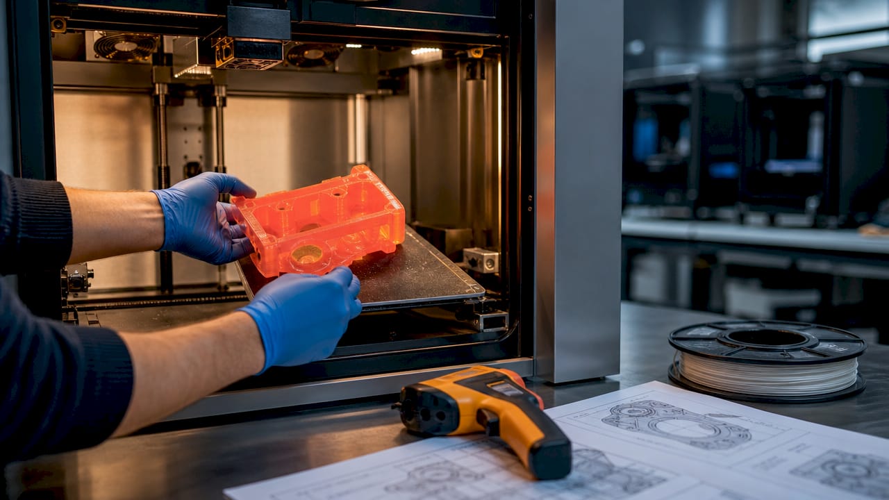
Engineer examining 3D printed prototype

Benefits of DFM in 3D Printing for Engineers


TL;DR:

  • Design for Manufacturability in 3D printing emphasizes designing parts to align with printer constraints, reducing print time, costs, and failures. Applying early DfAM principles enables part consolidation, improves strength through orientation, and accelerates prototypes, saving costs and time. Most failures result from late-stage design fixes; integrating DfAM from the start produces better products faster and lowers overall manufacturing expenses.

Design for Manufacturability, known in additive manufacturing circles as DfAM, is the practice of shaping a part’s geometry to work with a printer’s physical constraints rather than against them. The benefits of DFM in 3D printing are direct and measurable: faster print cycles, lower material costs, stronger parts, and fewer failed builds. Product developers who apply DfAM principles early catch problems before they become expensive. This article breaks down the top advantages, with specific techniques and data you can act on immediately.

1. How DFM reduces print time and material costs in 3D printing

Applying DFM principles to 3D printing cuts print times by 20–40% and lowers per-part costs by reducing support material and post-processing. That single change, designing geometry that holds itself up, is the highest-leverage move most engineers overlook.

The core technique is self-supporting geometry. Any surface angled greater than 45° from horizontal requires no support structures in FDM printing. Supports add print time, consume filament, and leave surface marks that require finishing work. Eliminating them cuts all three costs at once.

Specific geometry choices that reduce or eliminate supports:

  • Chamfers instead of horizontal overhangs. A chamfered edge at 45° prints cleanly. A flat horizontal ledge does not.
  • Teardrop holes instead of round holes. Circular holes printed horizontally sag at the top. A teardrop profile with a pointed apex is self-supporting.
  • Bridging spans under 5mm. Short horizontal gaps bridge cleanly without supports. Longer spans need either supports or a redesign.
  • Angled walls instead of vertical undercuts. Undercuts trap supports in hard-to-reach areas. Angled walls avoid the problem entirely.

Pro Tip: Design overhangs at 50° or steeper rather than exactly 45°. The extra margin accounts for real-world printer variation and reduces the chance of a borderline overhang failing mid-print.

Reducing post-processing effort is just as valuable as cutting print time. Support removal, sanding, and finishing can double the labor cost of a part. DfAM eliminates most of that work before the printer even starts.

2. Part consolidation and simplified assemblies

DfAM enables up to 90% part consolidation, reducing bill-of-materials complexity by 50–80% and eliminating assembly labor and mechanical fasteners. That is not a marginal gain. It changes the economics of a product line.
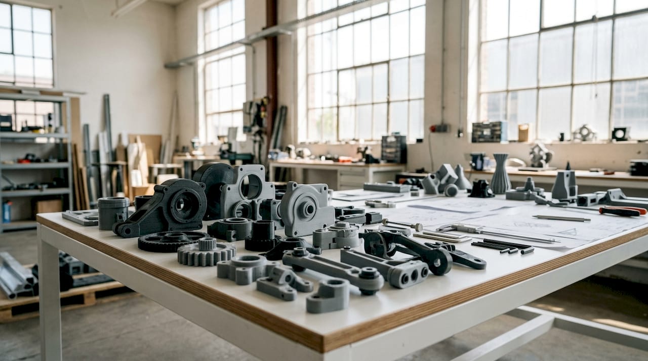
Overhead view of consolidated 3D printed parts

Traditional manufacturing forces engineers to split complex shapes into multiple pieces because molds and mills have geometric limits. 3D printing has no such constraint. A bracket, housing, and clip that once required three separate parts, three purchase orders, and an assembly step can print as one.

The practical benefits of consolidation follow a clear sequence:

  1. Fewer part numbers. Each eliminated component removes a purchase order, a supplier relationship, and a quality inspection point.
  2. No fastener costs. Screws, inserts, and adhesives add unit cost and assembly time. Consolidated parts need none.
  3. Reduced assembly risk. Every joint is a potential failure point. Fewer joints mean fewer failure modes.
  4. Simpler supply chains. Consolidating multiple parts into a single print reduces supply chain complexity and improves functional performance.
  5. Lower labor costs. Assembly time drops directly when there is nothing to assemble.

One important boundary: consolidation works best for static parts. Moving components, parts that need replacement, or assemblies requiring different materials should remain separate. Printing a hinge as one piece sounds appealing until the hinge wears out and the entire housing must be replaced.

3. Improving mechanical performance through design choices

3D printing is anisotropic. Interlayer bond strength is 50–70% of in-layer strength, which means a part’s orientation during printing directly determines where it will fail under load. This is the most underestimated mechanical variable in additive manufacturing.

The fix is straightforward: orient critical load paths parallel to the XY plane. A bracket that carries tensile load along its length should be printed so that load runs across layers, not between them. Engineers who treat print orientation as an afterthought consistently produce weaker parts than the material’s datasheet suggests.

Key design choices that improve mechanical performance:

  • Fillets on internal corners. Fillets increase part strength by up to 200% by spreading stress across a curved surface instead of concentrating it at a sharp corner. This is one of the highest-return changes available at zero material cost.
  • Internal lattice structures. Gyroid and octet truss lattices at 20–30% density deliver 80% of solid infill strength with significantly less material and print time. They outperform simple grid infill for most structural applications.
  • Wall thickness matched to load. Thin walls flex and fail. Walls at 3–4 perimeters handle most functional loads without adding unnecessary mass.
  • Avoid sharp internal transitions. Sudden changes in cross-section create stress risers. Gradual tapers distribute load more evenly.

Pro Tip: Do not default to 100% infill for structural parts. A gyroid pattern at 25% infill with four perimeter walls often outperforms solid infill in impact resistance while cutting print time by a third.

The 3D part optimization process for engineers goes deeper on matching infill patterns to specific load cases, which is worth reviewing before finalizing any functional part design.

4. Faster prototyping and fewer costly redesigns

The “Rule of 10” states that fixing a design issue becomes ten times more costly at each later stage of development. A change that costs $1 to fix in CAD costs $10 in prototyping, $100 in pre-production, and $1,000 after launch. DfAM shifts those fixes to the cheapest possible moment.

Engineers who integrate DfAM analysis before the first print catch geometry problems, wall thickness violations, and orientation issues in software rather than on the build plate. The result is fewer failed prints, fewer engineering change orders, and faster time to market.

Specific practices that accelerate prototyping cycles:

  • Run a printability check before slicing. Tools that flag unsupported overhangs, thin walls, and non-manifold geometry catch errors in minutes that would otherwise waste hours of print time.
  • Design for faster iteration cycles. Break complex parts into modular sections during early development. Print and test the critical feature first, not the entire assembly.
  • Validate wall thickness against your printer’s minimum. Most FDM printers require walls at least 1.2mm thick for structural integrity. Thinner walls print inconsistently and fail early in testing.
  • Use simulation before physical prints. FEA tools applied to the DfAM model identify weak points before any filament is consumed.

Early DFM involvement reduces overall project cost significantly by addressing manufacturing constraints before redesigns become necessary. The engineers who treat DfAM as a checklist item at the end of design consistently spend more time and money than those who run it in parallel with concept development.

Key Takeaways

DFM in 3D printing delivers the greatest returns when applied at the concept stage, not after the first failed print.

Point Details
Self-supporting geometry cuts costs Angles above 45° eliminate supports, reducing print time by 20–40% and post-processing labor.
Part consolidation changes economics DfAM enables up to 90% part consolidation, cutting BOM complexity by 50–80% and eliminating assembly steps.
Orientation determines strength Load paths parallel to the XY plane avoid the 50–70% interlayer strength penalty in FDM parts.
Fillets are free strength Internal corner fillets increase part strength by up to 200% with no added material cost.
Fix issues early or pay more The Rule of 10 means a design fix in CAD costs a fraction of the same fix after production starts.

Why most engineers get DfAM backwards

The most common mistake I see product developers make is treating DfAM as a finishing step. They complete the CAD model, send it to the printer, watch it fail, and then ask what went wrong with the print. The print did not go wrong. The design did.

The real value of DfAM is not in correcting prints. It is in making the design think like a printer from the first sketch. That shift requires cross-functional conversation between the engineer who owns the geometry and the person who understands the machine. When those two people work in parallel rather than in sequence, the number of failed builds drops sharply.

I have also seen teams resist part consolidation because it feels like a risk. Combining three parts into one means redesigning all three if something goes wrong. That logic sounds reasonable until you calculate the assembly labor, fastener costs, and supply chain overhead you are carrying every single production run. The consolidated part almost always wins on total cost.

The insight worth internalizing is this: viewing DfAM as simply printing traditional CNC designs misses its core value. Additive manufacturing unlocks geometries that subtractive methods cannot produce at any price. Engineers who design for those capabilities, rather than around them, build better products faster.

— Justin

Cc3dlabs brings DfAM expertise to your production workflow

Product developers who want DfAM applied from the first file, not retrofitted after a failed build, get better results with a manufacturing partner who understands both design and process.

https://cc3dlabs.com

Cc3dlabs offers professional 3D printing services built around manufacturing-grade quality, including design support, multi-color filament printing, and CAD modeling for clients near Philadelphia and shipping nationally. The team works with product developers and engineers on prototypes, functional parts, and batch production runs where DfAM principles are applied from the start. Getting a free online estimate takes minutes, and the design review process catches printability issues before they cost you a build. If you are ready to cut 3D printing costs through smarter design, Cc3dlabs is the right starting point.

FAQ

What are the main benefits of DFM in 3D printing?

DFM in 3D printing reduces print times by 20–40%, lowers material costs by eliminating support structures, improves part strength through better geometry, and cuts redesign costs by catching issues before production starts.

How does DfAM differ from traditional DFM?

Traditional DFM focuses on subtractive constraints like tool access and draft angles. DfAM focuses on additive constraints like overhang angles, layer orientation, and part consolidation opportunities that subtractive methods cannot achieve.

What is the 45° rule in 3D printing?

Surfaces angled greater than 45° from horizontal are self-supporting in FDM printing and require no support structures, which reduces print time, material use, and post-processing labor.

How much can part consolidation reduce assembly costs?

DfAM enables up to 90% part consolidation, which eliminates fasteners, reduces assembly time by 20 minutes or more per unit, and cuts BOM complexity by 50–80%.

When should DFM analysis happen in the design process?

DFM analysis should run in parallel with concept development. The Rule of 10 means fixing a design issue in CAD costs a fraction of fixing the same issue after production begins.
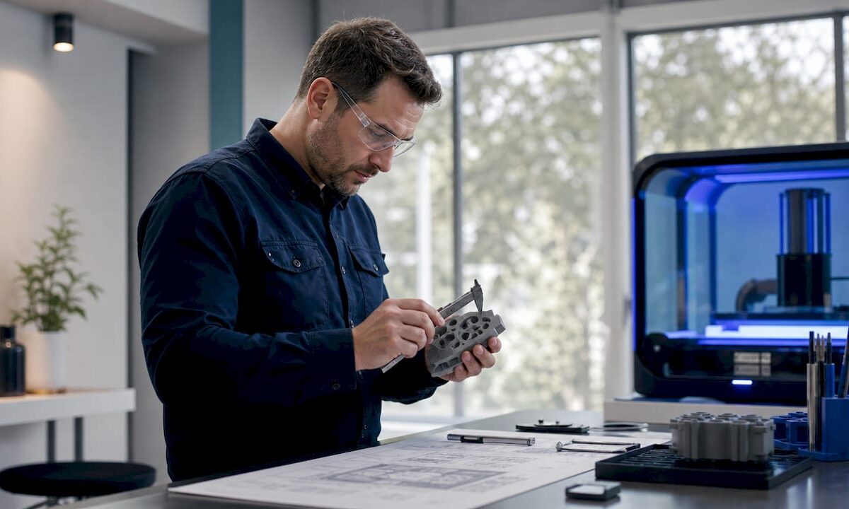
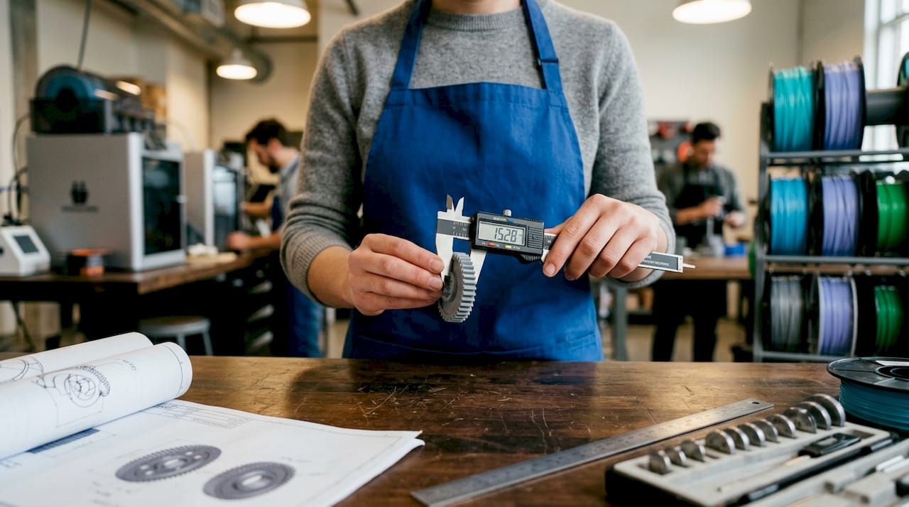
Engineer inspecting 3D printed part with calipers

Print Tolerance Standards Explained for Engineers


TL;DR:

  • Print tolerance standards define the acceptable dimensional deviations in 3D printed parts, ensuring proper fit and function. Achieving the correct tolerances depends on machine accuracy, material shrinkage, and thoughtful design to prevent errors and meet industry standards. Validating these tolerances through test prints and systematic measurement is essential for reliable, high-quality production.

Print tolerance standards define the allowable dimensional deviation in a 3D printed part so it fits and functions as designed. Get them wrong, and a press fit becomes a loose rattle or an immovable bond. Get them right, and assemblies snap together on the first try. Explaining print tolerance standards is not just an academic exercise. It is the difference between a prototype that validates your design and one that wastes a full production run. This guide covers fit types, material shrinkage, printer accuracy, and testing methods so you can build parts that meet spec every time.

What are print tolerance standards in 3D printing?

Print tolerance standards specify the maximum and minimum acceptable dimensions for a printed part relative to its nominal design size. The industry term for this concept is “dimensional tolerance,” and it maps directly to the ISO 286 system used in traditional machining. In 3D printing, tolerances are harder to hold because every variable, from filament diameter to bed temperature, shifts the final dimension.

Hands measuring 3D printed gear with caliper

Tolerance depends heavily on use case, fit type, printer model, and material. That means a single tolerance value cannot cover every situation. Engineers must define tolerances per feature, per material, and per machine class.

The practical consequence is significant. A part designed with a 0.2 mm clearance on a budget printer may come out with zero clearance because that machine holds only ±0.3 to ±0.5 mm on a good day. Mid-range machines tighten that to ±0.1–0.3 mm, and precision machines reach ±0.05–0.15 mm. Knowing your machine class before you set tolerances in CAD is the first rule of print quality standards.

What are the typical tolerance values for different fit types?

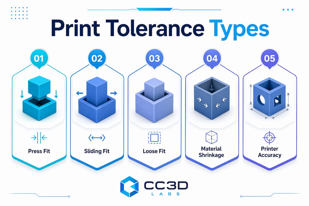
Fit type determines how much clearance or interference you build into mating parts. The three categories engineers use most are press fit, sliding fit, and loose fit.

Fit type Clearance or interference Typical use
Press fit -0.1 to -0.2 mm interference Permanent joints, bearing seats
Sliding fit 0.2–0.4 mm clearance Drawers, rails, moving assemblies
Loose fit 0.5–1.0 mm clearance Pins, alignment pegs, quick-swap parts

Infographic showing ranked print tolerance types and factors

Industry standards recommend 0.1 mm clearance for tight connectors, 0.2–0.4 mm for sliding parts, and 0.5–1.0 mm for loose pins. These values assume a mid-range printer and PLA or PETG. Material choice shifts the numbers considerably.

Press fit interference also varies by material. PLA requires -0.15 to -0.25 mm, PETG needs -0.20 to -0.30 mm, Nylon runs -0.30 to -0.40 mm, and TPU demands -0.40 to -0.60 mm because of its flexibility. A Nylon press fit designed with PLA values will pull apart under load. Always match interference values to the material you are actually printing.

Clearance for peg and hole features ranges from 0.2 mm per side for alignment to 0.4 mm or more for free movement. These are per-side values, so a 10 mm pin in a 10.4 mm hole has 0.2 mm clearance on each side. That distinction trips up many designers who apply total gap instead of per-side gap.

Pro Tip: Build a small test coupon with three or four fit types at different clearances before committing to a full print run. Ten minutes of test printing saves hours of rework.

How do material properties and shrinkage influence 3D print tolerances?

Shrinkage is the single most underestimated variable in understanding print tolerances. Every thermoplastic contracts as it cools, and that contraction pulls dimensions below the nominal CAD value.

The shrinkage rates by material are:

  • PLA: 0.3–0.5% shrinkage. Pre-scale models by 100.3–100.5% to compensate.
  • ABS and ASA: 0.8–1.2% shrinkage. These materials also warp without an enclosed chamber, which adds unpredictable dimensional error beyond simple scaling.
  • Nylon: 1.0–2.5% shrinkage. Pre-scaling by 100.5–102.5% is required, and even then, ambient humidity affects the final dimension because Nylon absorbs moisture.
  • TPU: Low shrinkage but high elasticity means interference values must account for the material springing back after assembly.
  • PETG: Moderate shrinkage, typically 0.4–0.6%, with better layer adhesion than PLA and less warping than ABS.

Pre-scaling compensates for uniform shrinkage, but shrinkage is rarely uniform. Tall parts shrink more in Z than in X or Y. Wide flat parts warp at the edges. The practical fix is to print a calibration cube, measure all three axes with calipers, and apply axis-specific scale factors in your slicer. A single global scale factor is a starting point, not a solution. Designers working with advanced filament materials should treat shrinkage compensation as a per-material, per-geometry workflow step rather than a one-time setting.

What printer and design factors affect adherence to print tolerance standards?

Printer accuracy sets the ceiling for what tolerances you can hold. Design choices determine whether you reach that ceiling or fall short of it.

Four factors control most of the dimensional error in filament-based printing:

  1. Calibration state. An uncalibrated extruder over-extrudes, which thickens walls and closes clearances. E-steps, flow rate, and linear advance settings all affect final dimensions. Recalibrate after every nozzle change or filament switch.

  2. Print orientation. Features printed in the XY plane hold tighter tolerances than features built up in Z. Layer lines in Z create stair-stepping on curved surfaces, which adds effective dimensional error. Orient critical mating surfaces to lie in the XY plane whenever possible.

  3. Elephant foot effect. The first layer spreads under nozzle pressure and bed adhesion, adding 0.2–0.5 mm to bottom dimensions. That extra material ruins press fits and prevents flat mating surfaces from seating correctly. Chamfering the base by 0.5 mm offsets this effect without requiring slicer compensation.

  4. Horizontal holes. Horizontal holes print undersized because filament sags across the unsupported span. Adding 0.2 mm to the hole diameter in CAD, or reorienting the part so the hole axis is vertical, corrects this consistently.

Pro Tip: Add a 0.5 mm chamfer to every base edge as a default in your CAD template. Experienced designers pre-chamfer bases to offset first-layer over-extrusion before the problem ever reaches the printer.

Design strategy matters as much as printer settings. Avoid sharp internal corners on mating features because filament rounds them, reducing effective clearance. Use drafting standards in 3D modeling to add draft angles on vertical walls, which improves dimensional consistency across the full height of a part. Split long mating surfaces into shorter segments to reduce the cumulative effect of warping on fit.

How can manufacturers and engineers test and validate print tolerance compliance?

Testing is the only way to confirm that your tolerance strategy works on a specific printer with a specific material. Assumptions based on spec sheets fail in practice because real-world conditions always differ from controlled lab conditions.

A systematic validation workflow includes these steps:

  • Print a tolerance cube. A 20 mm cube with labeled walls is the baseline. Measure all six faces with digital calipers. Any deviation from 20.00 mm tells you your scale factor and flow rate need adjustment before you print functional parts.

  • Use a pin and slot test model. Print a series of pins and matching slots with clearances ranging from 0.1 mm to 0.5 mm in 0.1 mm steps. The smallest clearance that allows free movement is your sliding fit baseline for that printer and material combination.

  • Apply go/no-go gauges. For production runs, go/no-go gauges are faster than calipers. A go gauge must pass through the feature; a no-go gauge must not. This binary check catches out-of-tolerance parts in seconds without requiring measurement skill.

  • Document results per material and printer. Calibration test prints with dimensional checks identify necessary tolerance adjustments for a given printer and material. Keep a log. When you switch filament brands or update firmware, rerun the test suite and compare against your baseline.

  • Iterate in CAD, not in post-processing. Sanding and drilling to fix tolerance errors is a one-off fix that does not scale. Adjust the CAD model, reprint, and retest. Three iterations typically converge on a working tolerance for a new material and printer combination.

For engineers managing part validation in 3D printing, this workflow should be formalized as a standard operating procedure before any part moves from prototype to batch production.

Key takeaways

Print tolerance standards require matching fit type, material shrinkage, and printer accuracy before a single layer is deposited, because correcting dimensional errors after printing costs more than designing them out.

Point Details
Fit type sets the baseline Press fits need -0.1 to -0.2 mm interference; sliding fits need 0.2–0.4 mm clearance.
Material shrinkage shifts dimensions PLA shrinks 0.3–0.5%; Nylon shrinks up to 2.5% and requires axis-specific scale compensation.
Printer class limits achievable tolerance Budget machines hold ±0.3–0.5 mm; precision machines reach ±0.05–0.15 mm.
Design choices prevent common errors Chamfer bases by 0.5 mm and add 0.2 mm to horizontal hole diameters to offset known print artifacts.
Test before committing to production Pin and slot test prints plus go/no-go gauges validate tolerances faster than caliper-only inspection.

Why I think most engineers underestimate tolerance testing

Most engineers I work with treat tolerance as a CAD problem. They set a clearance value, send the file, and expect the printer to deliver. The printer does not care about your CAD intent. It responds to calibration state, ambient temperature, filament moisture, and a dozen other variables that shift from one print session to the next.

The engineers who consistently hit tight tolerances share one habit: they test systematically and document everything. They know their printer’s actual accuracy range, not the spec sheet range. They know how their preferred Nylon brand behaves after sitting in a humid shop overnight versus a dry box. That knowledge comes only from running test prints and keeping records.

The other thing I have seen change outcomes is designer-engineer collaboration at the tolerance-setting stage, not after the first failed prototype. When the person who understands the assembly function talks to the person who understands the printer before the CAD is finalized, the first print usually fits. When those conversations happen after a failed batch, you are paying twice.

Emerging technologies like in-process dimensional monitoring and closed-loop slicer feedback are starting to reduce the gap between intended and actual dimensions. But in 2026, systematic testing and documentation remain the most reliable path to reliable 3D prototyping that holds tolerance across a full production run.

— Justin

Cc3dlabs precision printing for functional parts

Cc3dlabs operates near Philadelphia and specializes in filament-based 3D printing for functional prototypes, production parts, and batch orders where dimensional accuracy is not optional.

https://cc3dlabs.com

Every order at Cc3dlabs starts with a review of fit requirements, material selection, and tolerance targets before a file goes to the printer. The team supports press fits, sliding assemblies, and loose-fit components across PLA, PETG, Nylon, TPU, and specialty filaments. For engineers who need parts that meet spec on the first run, Cc3dlabs offers professional 3D printing services with design support, free online estimates, and local pickup or shipping. If your current workflow is producing out-of-tolerance parts, the right starting point is a conversation about material, machine, and fit requirements.

FAQ

What is a standard tolerance for 3D printed parts?

Standard tolerances range from ±0.3–0.5 mm on budget printers to ±0.05–0.15 mm on precision machines. The right value depends on fit type, material, and the specific printer being used.

How much clearance should I add for a sliding fit?

A sliding fit requires 0.2–0.4 mm of clearance between mating surfaces. Start at 0.3 mm for a mid-range printer with PLA or PETG, then adjust based on test print results.

Why do my 3D printed holes come out too small?

Horizontal holes print undersized because filament sags across the unsupported span during printing. Add 0.2 mm to the hole diameter in CAD or reorient the part so the hole axis is vertical.

How do I compensate for material shrinkage in 3D printing?

Pre-scale your model by the inverse of the shrinkage rate. PLA needs 100.3–100.5% scaling; Nylon may need up to 102.5%. Measure a calibration cube after printing and apply axis-specific corrections for best results.

What is the fastest way to validate print tolerances?

Print a pin and slot test model with clearances from 0.1 mm to 0.5 mm in 0.1 mm steps. The smallest clearance that allows free movement is your working sliding fit tolerance for that printer and material.

Female engineer reviewing 3D CAD model on monitor

Why 3D Model Verification Is Important for Engineers


TL;DR:

  • D model verification ensures geometric accuracy, structural integrity, and production readiness before manufacturing begins. It prevents costly downstream errors by detecting hidden issues early through systematic checks and structured milestones.

3D model verification is the proactive process of checking digital models for geometric accuracy, structural integrity, and production readiness before a single part is manufactured. Skip it, and you risk cascading errors: wrong units, broken mesh geometry, and incompatible file formats that surface only after fabrication has started. For product developers and engineers, understanding why 3D model verification is important is not a theoretical exercise. It is the difference between a clean production run and an expensive rework cycle that kills your schedule.

Why 3D model verification is important: the core case

A visually correct CAD model can still contain hidden errors like broken references or faulty geometry that cause manufacturing and documentation failures. That is the central problem with relying on visual inspection alone. What looks right on screen can be fundamentally wrong in the data.

The industry term for this process is CAD validation or 3D model quality assurance, and it covers far more than a visual check. It includes mesh integrity tests, unit consistency checks, topology evaluation, and downstream compatibility verification. Engineers who treat these as optional steps tend to discover their errors at the worst possible time: after tooling has been cut or parts have been printed.

Spatial and geometric tests are risk management steps that prevent downstream pipeline failures. Failing to run them early means discarding hours of subsequent texturing, rigging, or manufacturing prep work. The cost is not just time. It is the compounding effect of every downstream step built on a flawed foundation.

Structured, multi-stage review milestones such as 30%, 60%, and 90% audits are professional standards in 2026 to catch errors early and prevent cascading issues. These checkpoints are not bureaucratic overhead. They are the mechanism that keeps small geometry problems from becoming full production failures.

What are the key components of effective 3D model verification?

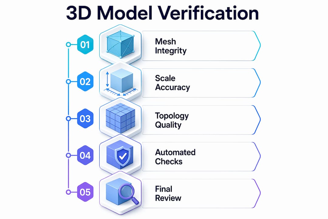
Effective verification checks several distinct layers of a model, and each layer catches a different class of error.

Infographic depicting steps of 3D model verification process

Mesh integrity is the first line of defense. Common faults include reversed normals, non-manifold edges, and open shells. A non-manifold edge, for example, is one shared by more than two faces. Slicers and manufacturing software cannot process these correctly, which means a model that looks solid will fail at the fabrication stage.

Scale accuracy and unit consistency are equally critical. A model built in millimeters but exported as inches will produce a part that is 25.4 times the intended size. This error is trivially easy to make and surprisingly common when files move between different CAD environments or teams.

Topology quality determines how a model behaves in downstream workflows. Good topology supports deformation, subdivision, and efficient rendering essential for production use. For functional parts, poor topology can cause stress concentration points that only appear under load testing.

Verification criterion Common fault Impact on production
Mesh integrity Non-manifold edges, open shells Slicer failure, fabrication rejection
Scale and units Unit mismatch between environments Incorrect part dimensions
Topology quality Irregular polygon flow, T-junctions Deformation errors, rendering artifacts
UV and texture mapping UV overlap, incorrect color space Visual defects in rendered or printed parts
Watertightness Holes in mesh surface Failed 3D print, unusable geometry

The table above shows why no single check is sufficient. Each criterion targets a different failure mode.

Pro Tip: Run a slicer pass as a final mesh integrity check before submitting any model for fabrication. A clean slicer pass rate is one of the strongest predictors of a successful print.

Automated quality assurance catches 95% of common mesh and texture flaws, freeing engineers to focus manual effort on nuanced topology and functional assessments. That 5% gap is where expert human review earns its value.

Hands using tablet for 3D model verification

How does 3D model verification prevent costly downstream errors?

The timing of error discovery is everything in product development. An error caught at the 30% design milestone costs a fraction of what the same error costs after manufacturing has begun. This is not an opinion. It is a structural feature of how production pipelines work: every downstream step adds cost and time to any upstream mistake.

CAD validation reduces rework and supports compliance by confirming models meet dimensional and functional requirements before production. Validated models also improve coordination between design, manufacturing, suppliers, and stakeholders. That coordination benefit alone justifies the time investment.

The most common costly errors that verification prevents include:

  1. Incorrect units or scale causing parts to be fabricated at the wrong size, requiring full reprints or remachining.
  2. Non-manifold geometry causing slicer failures that halt production until the model is repaired.
  3. Missing or broken references in assembly files that cause incorrect bill-of-materials outputs and procurement errors.
  4. Incompatible geometry between mating parts that only surfaces during physical assembly, requiring redesign.
  5. Wrong color spaces or UV errors in models destined for multi-color or textured printing, causing visual defects in finished parts.

Each of these errors is detectable before fabrication with a structured verification workflow. Each becomes significantly more expensive after fabrication has started.

A CAD model’s readiness is defined by downstream compatibility. If later pipeline steps require manual repair, the model fails validation regardless of how good it looks. Avoiding the “polish later” mindset is the single most effective habit engineers can build.

Pro Tip: Treat the 30% review milestone as your geometry checkpoint. Confirm mesh integrity, units, and scale before investing time in detailed features or surface finishing.

For engineers using part validation in 3D printing, catching errors at the design stage eliminates the most common causes of print failure and part rejection.

What tools and workflows make verification more effective?

Automated verification tools handle the high-volume, rule-based checks that would take hours to run manually. Automated scripts efficiently filter fundamentally broken models, saving manual inspection time for advanced subjective assessment like topology flow. This hybrid approach is the current best practice for production-ready asset pipelines.

A tool-agnostic mindset centered on core 3D spatial principles is more valuable than relying on any single software validator. Models must survive across multiple pipelines, and a check that passes in one environment may fail in another if the underlying geometry is marginal.

Recommended verification techniques for engineers:

  • Automated mesh analysis: Checks for non-manifold edges, reversed normals, open shells, and degenerate faces. Most slicer software includes basic versions of these checks.
  • Bounding box validation: Confirms the model occupies the correct volume and that scale has not been corrupted during export.
  • UV and color space checks: Verifies UV utilization thresholds and correct color spaces (sRGB for display, Linear for rendering) to prevent texture errors.
  • Watertightness testing: Confirms the mesh is a closed solid with no holes, which is a hard requirement for most 3D printing workflows.
  • Topology review: Manual or semi-automated assessment of polygon flow, edge loops, and face count relative to the model’s intended use.

Validation is the indispensable gatekeeper that converts generative AI models into reliable, shippable assets by enforcing deterministic outputs and quality criteria. As generative modeling tools become more common in product development, this gatekeeper role becomes more critical, not less.

Pro Tip: Never defer spatial validation to the end of your workflow. Run geometry and scale checks immediately after the initial model is built, before any texturing or assembly work begins.

For a structured approach to validating 3D designs within manufacturing workflows, building these checks into your standard operating procedure is the fastest way to reduce defect rates.

How should product developers integrate verification into their process?

Verification works best when it is built into the project timeline from the start, not added as a final gate before production. The 3D modeling process for businesses should include defined verification checkpoints at each major milestone.

Project phase Verification activities Goal
Concept (30%) Geometry check, unit confirmation, scale validation Confirm foundational model integrity
Development (60%) Topology review, assembly fit check, reference validation Catch functional and compatibility errors
Pre-production (90%) Full mesh audit, slicer pass, UV and texture check Confirm production readiness
Final release File format validation, documentation check Ensure handoff package is complete

Cross-functional coordination between design, manufacturing, and quality teams is what makes this schedule work. Each team brings a different perspective on what “correct” means for a model. Design teams check intent. Manufacturing teams check producibility. Quality teams check compliance. All three views are needed.

Defining verification criteria early, before modeling begins, prevents the most common source of late-stage conflict: disagreement about what the model was supposed to achieve. A shared checklist, agreed upon at project kickoff, gives every team a common standard to work toward.

Drafting standards in 3D modeling provide the structured review checkpoints that keep multi-team projects aligned and reduce handoff errors between design and production.

Pro Tip: Embed verification criteria into your project brief at kickoff. When every team knows the acceptance standards from day one, late-stage surprises drop dramatically.

Verification is not a formality. It is the work.

I have reviewed hundreds of models that looked production-ready on screen and failed within the first automated check. The pattern is consistent: teams that treat verification as a final approval step always find their worst errors at the worst time. Teams that build it into every milestone find the same errors when they are still cheap to fix.

The most underestimated risk in product development is not a bad design. It is a good design with a bad model. A brilliant concept built on non-manifold geometry or mismatched units will fail in fabrication just as reliably as a poor design. The geometry does not care how good the idea is.

Generative AI tools are making this problem more acute, not less. AI-generated models can look convincing while containing structural errors that no human would introduce manually. Machine-verifiable tests for topology, watertightness, and schema conformance are now essential for any team using generative modeling in their pipeline. The speed of AI generation means errors can propagate faster than ever before.

My strongest recommendation is this: build a verification culture, not just a verification step. When every engineer on your team treats geometry integrity as their personal responsibility, not the QA team’s problem, error rates drop and project timelines stabilize. Verification is not overhead. It is the work.

— Justin

Cc3dlabs supports precision from model to finished part

Cc3dlabs works with product developers and engineers near Philadelphia and ships nationally, providing professional 3D printing services built around verified, high-accuracy models. Every project starts with a model review to confirm the file is production-ready before printing begins.

https://cc3dlabs.com

Validated CAD files and high-accuracy 3D scan data feed directly into Cc3dlabs’ filament-based printing workflow, producing prototypes and functional parts that match design intent. Whether you need a single prototype or a batch production run, Cc3dlabs offers free online estimates, design support, and fast turnaround. Submit your model for a free estimate and get a clear picture of what your verified design will cost to produce.

FAQ

What is 3D model verification?

3D model verification is the process of checking a digital model for geometric accuracy, unit consistency, mesh integrity, and downstream compatibility before fabrication. It is also called CAD validation or 3D model quality assurance.

Why do visually correct models still fail in production?

A model can appear correct on screen while containing hidden errors like non-manifold edges, broken references, or wrong units. These errors only surface when the model enters a slicer, manufacturing software, or assembly workflow.

When should verification happen in a project?

Verification should happen at the 30%, 60%, and 90% milestones of a project, not only at the end. Early checks catch foundational errors before downstream work amplifies their cost.

How does automated verification differ from manual review?

Automated verification catches up to 95% of common mesh and texture flaws through rule-based checks. Manual review handles nuanced assessments like topology flow and functional fit that require expert judgment.

What is the biggest risk of skipping 3D model verification?

The biggest risk is discovering errors after fabrication has started, when the cost to correct them is highest. Unverified models frequently cause slicer failures, incorrect part dimensions, and assembly incompatibilities that require full redesign.


Key takeaways

3D model verification is the most cost-effective risk management step in product development, and errors caught before fabrication cost a fraction of what they cost after production begins.

Point Details
Verify early and often Run geometry and scale checks at the 30%, 60%, and 90% project milestones.
Automate first, then review Automated tools catch 95% of common flaws; use manual review for topology and functional fit.
Visual inspection is not enough Hidden errors like non-manifold edges and wrong units require systematic checks to detect.
Define criteria at kickoff Agree on acceptance standards before modeling begins to prevent late-stage team conflicts.
Verification enables AI workflows Machine-verifiable tests are now required to make generative AI models production-ready.
Engineer inspecting 3D-printed high-temp filament part

Why Use High-Temp Filaments for Engineering-Grade Parts


TL;DR:

  • High-temp filaments can withstand continuous service temperatures above 150°C and resist chemicals and flames. They enable durable parts in aerospace, automotive, and medical sectors where high thermal and chemical resistance are essential. Proper hardware, including hotends and heated chambers, is necessary for successful printing with these advanced materials.

High-temp filaments are 3D printing materials engineered to maintain structural integrity at continuous service temperatures above 150°C, far beyond what standard PLA or ABS can handle. The industry term for this material class is “high-performance engineering thermoplastics,” and understanding why use high-temp filaments starts with one fact: standard filaments fail where these materials thrive. PLA deflects at roughly 60°C. ABS holds up past 100°C. But the moment you need a part that survives an engine bay, an autoclave, or a chemical processing line, you need a different class of material entirely. Heat Deflection Temperature (HDT) is the key metric that separates these tiers, and it drives every material decision in this space.

What are the main benefits of using high-temperature filaments?

High-temp filaments deliver four core advantages that standard materials cannot match: thermal stability, mechanical strength, chemical resistance, and flame retardancy. Each one matters in a different way depending on your application.

Hands removing hot 3D-printed polycarbonate part

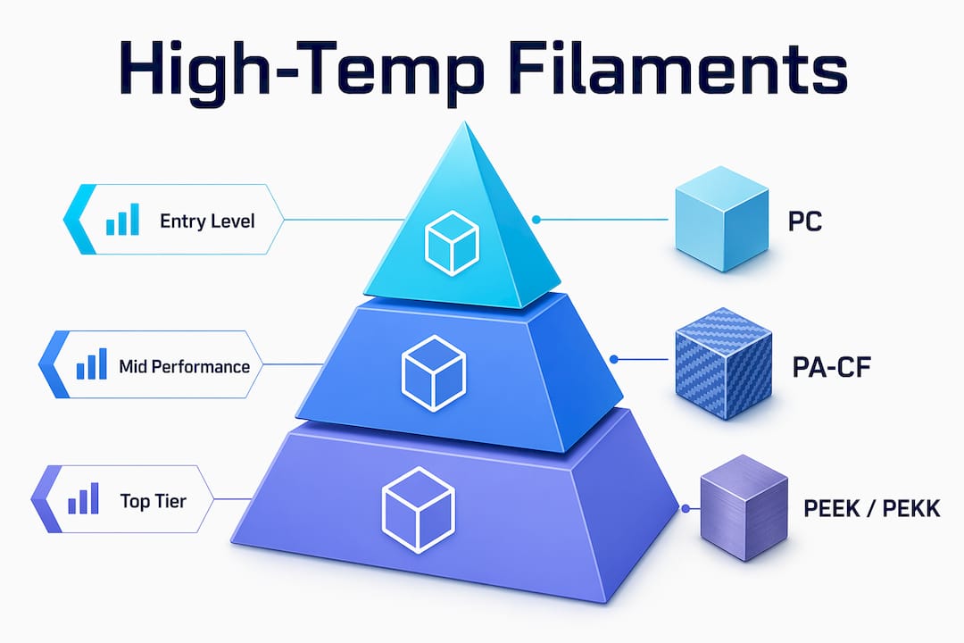
Thermal stability is the most obvious benefit. Parts printed in polycarbonate (PC) hold their shape up to approximately 140°C HDT. Nylon composites like PA-CF push that threshold to 150–180°C. PEI (also marketed as ULTEM) exceeds 200°C, and PEEK or PEKK top out above 250°C. That range covers nearly every industrial thermal environment outside of direct flame contact.

Mechanical performance is where these materials separate themselves from consumer filaments. High-temp thermoplastics offer high impact strength, tensile strength, and fatigue resistance. A PA-CF bracket on a vibrating assembly line will outlast a PLA version by orders of magnitude. The fiber reinforcement in carbon-filled nylon composites also improves stiffness without adding significant weight.

Infographic ranking high-temp filament materials by performance

Chemical resistance is critical for fluid-contact applications. High-temp filaments resist automotive fluids, fuels, oils, acids, and industrial cleaning agents. A standard ABS part submerged in brake fluid will swell and crack. A PEEK part will not.

Flame retardancy adds a compliance dimension. PEI carries a UL 94 V-0 flame rating, which is the highest classification for self-extinguishing plastics. That rating matters directly for aerospace interiors, medical enclosures, and consumer electronics housings where fire safety standards are non-negotiable.

  • Superior heat resistance prevents deformation in hot environments
  • High tensile and impact strength for load-bearing functional parts
  • Chemical resistance to fuels, oils, acids, and solvents
  • UL 94 V-0 flame retardancy in select materials like PEI
  • Long service life for tooling, fixtures, and end-use components

Pro Tip: When evaluating a high-temp filament for a new application, check both the HDT and the continuous service temperature. HDT is measured under load for a short period. Continuous service temperature reflects long-term real-world performance, and the gap between the two can be significant.

Which industries and applications benefit most from high-temp filaments?

High-temp filaments open possibilities for durable, functional parts in roles previously limited to metals, enabling weight savings and corrosion resistance across multiple sectors. The industries below represent the highest-value use cases.

  • Aerospace: PEI is certified to FAR 25.853 for aircraft interior components, covering flame, smoke, and toxicity requirements. PEEK is used for structural brackets and ducting where metal replacement saves meaningful weight.
  • Automotive: Parts near engines, exhaust systems, or fluid reservoirs require both thermal and chemical resistance. PA-CF and PEI handle these environments reliably, and 3D printing allows rapid iteration on bracket and housing geometry.
  • Medical devices: PEI and PEEK are biocompatible and withstand repeated steam sterilization in autoclaves. PEEK’s mechanical properties rival some metals, making it suitable for surgical guides, implant trials, and instrument housings.
  • Industrial tooling and fixtures: Jigs, clamps, and assembly fixtures printed in PC or PA-CF endure prolonged mechanical stress and elevated temperatures on factory floors without creeping or deforming.
  • Consumer electronics: Enclosures for power electronics, motor controllers, and battery management systems benefit from the flame retardancy and dimensional stability of PEI and PC.

The common thread across all these sectors is that the part must perform reliably under conditions that would degrade a standard filament within hours. For engineers and product developers who need to choose filaments for engineering parts, the application environment is the starting point for every material decision.

What hardware do you need to print high-temp filaments?

Printing high-temp filaments requires hardware that most consumer desktop printers cannot provide. The gap between a standard FDM machine and an industrial-grade system is not a minor calibration issue. It is a fundamental equipment difference.

  1. All-metal hotend: Standard PTFE-lined hotends degrade above 260°C, releasing toxic fumes and contaminating prints. An all-metal hotend is mandatory for materials like PEEK and PEI that require extrusion temperatures of 300°C or higher. This is a non-negotiable hardware upgrade, not an optional accessory.

  2. Actively heated print chamber: A passive enclosure slows heat loss but does not maintain a stable ambient temperature. An actively heated chamber prevents warping by keeping the part at a controlled temperature throughout the print. Without it, semi-crystalline polymers like PEEK suffer delamination and brittleness as layers cool unevenly.

  3. High-temperature heated build plate: Bed temperatures of 100°C or higher are required for adhesion with most high-temp materials. PC typically needs 110–120°C. PEEK may require 160°C or more. A standard 60°C bed will not hold these parts.

  4. Filament dryer or dry storage: Moisture absorption in nylon-based filaments causes steam bubbles during extrusion, producing brittle, porous parts. Drying PA-CF at 80–90°C for 8–12 hours before printing is standard practice, not optional preparation.

  5. Rigid, thermally stable frame: High chamber temperatures cause thermal expansion in printer frames. Industrial machines use aluminum or steel frames designed to maintain dimensional accuracy at elevated ambient temperatures.

Pro Tip: If you are printing PA-CF or PEI for the first time, run a filament drying cycle even on a freshly opened spool. Moisture absorbs during shipping and storage, and a single wet print can ruin an expensive spool and a long print job.

The printer setup requirements for high-temp materials are well-documented, but engineers frequently underestimate how much the chamber environment affects final part quality. Active heating is the single most impactful upgrade after the hotend.

How do different high-temp filament types compare?

Not all high-temp filaments are equal in performance, processability, or cost. The right choice depends on your thermal target, mechanical requirements, and available hardware.

Polycarbonate (PC) is the entry point for high-temp printing. It offers an HDT of approximately 140°C and good impact resistance, and it bridges the gap between consumer and engineering filament tiers. PC teaches you the fundamentals of high-temp printing without requiring a full industrial machine.

PA-CF (carbon fiber reinforced nylon) pushes thermal performance to 150–180°C while adding stiffness and strength from the carbon fiber fill. The trade-off is hygroscopicity. Nylon absorbs moisture aggressively, and PA-CF parts must be dried before and during printing to maintain quality.

PEI (ULTEM) is the aerospace and medical workhorse. Its amorphous polymer structure gives it dimensional stability and easier printing than semi-crystalline alternatives. The UL 94 V-0 rating and FAR 25.853 certification make it the default choice for regulated industries.

PEEK and PEKK represent the top tier. PEEK has an HDT exceeding 250°C and mechanical properties that rival some metals. It requires controlled slow cooling in a heated chamber to develop the optimal crystalline structure. The hardware cost is high, and the process window is narrow, but no other printable polymer matches its performance ceiling.

Material HDT Key Strength Main Challenge
Polycarbonate (PC) ~140°C Impact resistance, accessible Moisture sensitivity, warping
PA-CF (Nylon CF) 150–180°C Stiffness, strength-to-weight Highly hygroscopic, needs drying
PEI (ULTEM) 200°C+ Flame retardancy, certifications High print temp, material cost
PEEK / PEKK 250°C+ Near-metal strength, biocompatible Expensive hardware, narrow process window

For engineers exploring advanced filament materials, the table above is a starting framework. Real-world selection requires testing under actual service conditions, not just comparing spec sheets.

Key takeaways

High-temp filaments are the correct material choice when a part must survive temperatures above 140°C, contact with chemicals, or regulated flame-retardancy requirements.

Point Details
HDT defines material selection Match the filament’s HDT to your application’s peak operating temperature, not average temperature.
Hardware is non-negotiable All-metal hotends and actively heated chambers are required, not optional, for PEEK and PEI.
Moisture ruins expensive prints Dry all hygroscopic filaments like PA-CF and PEI before every print run to prevent voids and brittleness.
Start with polycarbonate PC teaches high-temp printing fundamentals at lower hardware cost before advancing to PEEK or PEI.
Certifications drive industry adoption PEI’s UL 94 V-0 and FAR 25.853 ratings make it the default for aerospace and medical applications.

What I’ve learned from printing with high-temp materials

The most common mistake I see engineers make is treating high-temp filament selection as a spec-sheet exercise. They find a material with the right HDT, order a spool, and load it into a machine that was never designed for it. The print fails, they blame the filament, and they walk away thinking PEEK or PEI is not ready for production use.

The hardware foundation is everything. An all-metal hotend and an actively heated chamber are not upgrades you add later. They are prerequisites. I have seen teams spend weeks troubleshooting delamination and warping in PEEK parts before realizing their chamber was passively enclosed, not actively heated. The fix was a hardware change, not a slicer setting.

Moisture management is the second failure point that catches people off guard. Nylon composites absorb humidity fast. I have opened a spool that sat on a shelf for three days and found it wet enough to produce audible popping during extrusion. A dedicated filament dryer running continuously during long print jobs is not excessive. It is standard practice for anyone printing PA-CF or PEI at volume.

My practical advice: start with polycarbonate. It runs at lower temperatures than PEEK or PEI, it teaches you the warping and adhesion behavior of high-temp materials, and it produces genuinely useful parts. Once you have dialed in your hardware and process with PC, the transition to PEI is manageable. PEEK is a different level entirely and deserves its own dedicated machine and process development time.

The payoff for getting this right is real. Once your process is dialed in, high-temp filaments produce parts with repeatability and mechanical performance that justify the investment many times over.

— Justin

Cc3dlabs prints engineering-grade filaments for demanding applications

Engineers and product developers who need functional prototypes or end-use parts in high-temp materials do not always have the hardware or process expertise in-house. CC 3D Labs, based near Philadelphia, operates a professional FDM print farm running engineering-grade filaments including polycarbonate (PC) and carbon-fiber nylon (PA-CF) for prototyping and production runs. Ultra-high-temperature polymers like PEI (ULTEM) and PEEK require industrial systems beyond standard service FDM equipment — if your part truly needs them, we’ll say so up front and point you toward the right process.

https://cc3dlabs.com

The team at Cc3dlabs advises on material selection based on your application’s thermal, mechanical, and regulatory requirements. Whether you need a single prototype or a batch of functional parts, Cc3dlabs provides free online estimates, design support, and fast turnaround with local pickup or shipping. If your part needs to survive heat, chemicals, or a certification audit, Cc3dlabs has the equipment and expertise to print it correctly the first time.

FAQ

What temperature can high-temp filaments withstand?

High-temp filaments cover a wide range: polycarbonate holds up to approximately 140°C HDT, PEI exceeds 200°C, and PEEK surpasses 250°C. The right threshold depends on your application’s peak operating temperature and load conditions.

Why can’t I print PEEK on a standard desktop printer?

Standard PTFE-lined hotends degrade above 260°C and release toxic fumes, making them unsafe for PEEK extrusion temperatures of 370–400°C. PEEK also requires an actively heated chamber to prevent delamination, which most consumer machines do not provide.

Is PEI safe for medical and aerospace applications?

PEI is certified to FAR 25.853 for aircraft interiors and carries a UL 94 V-0 flame rating, making it the standard choice for regulated aerospace and medical applications. Its amorphous structure also gives it better dimensional stability than semi-crystalline alternatives like PEEK.

Do I need to dry high-temp filaments before printing?

Drying is required for all hygroscopic high-temp filaments, particularly nylon composites and PEI. Moisture absorbed during storage causes steam bubbles during extrusion, producing brittle, porous parts that waste expensive material.

When should I use high-temp filaments instead of standard materials?

Use high-temp filaments when your part will face continuous temperatures above 100°C, contact with chemicals or fuels, prolonged mechanical stress, or flame-retardancy compliance requirements. For parts that operate below those thresholds, standard materials like PETG or ABS are sufficient and easier to process.

1 2 3 5