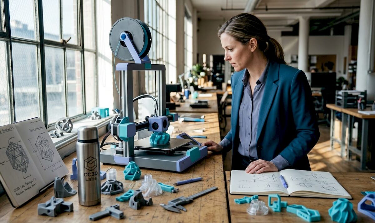
Engineer measuring freshly 3D printed part

What are tolerances in 3D printing: an engineer’s guide


TL;DR:

  • Understanding and applying proper tolerances in 3D printing are essential for functional, accurately fitting parts, as printer technology, part size, and orientation significantly influence achievable precision.
  • Designers must consider tolerance as a key early input, choosing appropriate clearance or interference fits, orienting critical features in the XY plane, and accounting for material behavior and shrinkage to ensure successful assembly.

If you have ever printed a part from a perfect CAD model only to find it won’t snap together, rotates when it should be fixed, or gaps where it should seal, you already understand why tolerances in 3D printing are not optional knowledge. Tolerance is the designed allowance for dimensional deviation in a part, and every functional component you print lives or dies by how well you understand and apply it. This guide gives you the practical framework to design parts that actually work when they come off the build plate.


Table of Contents

Key Takeaways

Point Details
Tolerance vs accuracy Tolerance is the allowed range of dimensional deviation; accuracy is how close a print is to the CAD model.
Technology choice matters Different 3D printing methods offer varying tolerance capabilities impacting final part precision.
Design influences outcome Part size, geometry, orientation, and material affect achievable tolerances and must be considered early.
Design for assembly Use intentional clearances tailored to fit types and printing technology for functional parts.
Verify and measure Assess vendor specs for bias and precision, and validate prints to ensure tolerances are met.

Understanding tolerances in 3D printing: accuracy, precision, and what actually matters

These three terms get used interchangeably in shop conversations, and that confusion causes real problems at the design stage. Tolerance is the range of acceptable deviation designed into the part; accuracy measures how close the printed dimension is to your CAD model; and precision measures whether the printer reproduces that same dimension reliably across multiple prints.

Here is why the distinction matters in practice:

  • Tolerance is a design decision. You set it in your CAD file based on what the part needs to do.
  • Accuracy is a machine and process characteristic. A printer might consistently produce parts 0.2 mm undersize, which is a bias, not a random error.
  • Precision is about repeatability. A precise printer gives you the same result every run, even if that result drifts slightly from nominal.

A printer can be precise but not accurate (it produces the same wrong dimension every time), or accurate on average but imprecise (results scatter around the target). For functional parts, you need both, and your tolerance band must be wide enough to accommodate whichever combination of bias and scatter your process exhibits.

For a broader orientation to how these concepts fit into the vocabulary of additive manufacturing, the 3D printing terminology explained resource at CC 3D Labs is worth bookmarking before you go further into process selection.


How different 3D printing technologies impact tolerance capabilities

Technology choice is your single biggest lever for dimensional control. The typical tolerance ranges vary significantly by process, as shown in the table below.

Technology Typical tolerance Minimum tolerance
Carbon DLS ±0.1% ±0.1 mm
Polyjet ±0.1 mm (first 10-20 mm) +±0.05 mm per additional mm
DMLS ±0.2% ±0.1 to 0.2 mm
MJF ±0.3% ±0.2 mm
SLS ±0.3% ±0.3 mm
SLA ±0.5% ±0.2 mm
FDM ±0.5% ±0.5 mm

A few things that table does not make obvious on its own:

  • Percentage-based tolerances scale with part size. An MJF part at 200 mm carries ±0.6 mm of tolerance just from the percentage component, regardless of minimum value. For large structural components, that adds up fast.
  • SLA trades resolution for material limitations. SLA can hold ±0.2 mm on small features beautifully, but photopolymers are sensitive to UV exposure after printing, which can cause post-cure dimensional drift if you are not controlling the process.
  • FDM’s ±0.5 mm floor is non-negotiable for most off-the-shelf machines. You can improve on it with process control and calibration, but designing FDM parts that require ±0.1 mm without post-processing is setting yourself up for failure.
  • DMLS and Carbon DLS are the precision leaders, but they require capital investment or premium service pricing that only makes sense when the application demands it.

Pro Tip: Make the technology decision before you finalize your CAD geometry, not after. Designing for SLA and then switching to FDM to cut cost almost always means a complete tolerance review of every mating feature.

If you are evaluating whether your project qualifies for tighter process control, the manufacturing-grade 3D printing guide at CC 3D Labs covers where the bar sits for production-intent parts.


Key factors influencing tolerances: size, orientation, and material behavior

Machine specs tell you the best-case scenario. Real parts live in a messier world where tolerances depend on part size, material, and geometry, and larger parts shrink more, warp differently, and require active compensation in your process.

Here is what to account for in your design and build planning:

  • Part size and shrinkage. Polymers contract as they cool. A 10 mm feature might land within ±0.1 mm. That same shrinkage rate applied to a 150 mm span produces an error that can easily exceed your tolerance band without scaling compensation in the slicer or at the printer.
  • Build orientation. This is one of the most underused variables in tolerance management. Orienting a mating surface parallel to the XY build plane can deliver up to 2x better dimensional accuracy than running that same surface vertically. The XY tolerances typically outperform Z tolerances across every major printing technology, and features under 25 mm achieve the tightest specs when kept within the XY plane.
  • Z-axis limitation. Layer height directly sets a floor on Z precision. A 0.2 mm layer height means you cannot meaningfully hold a Z dimension to tighter than that layer value, regardless of what the machine spec sheet says.
  • Material selection. Glass-filled PA12 (polyamide with glass fiber reinforcement) dramatically reduces the tolerance spread compared to standard nylon because it resists shrinkage anisotropy. Flexible TPU, by contrast, is nearly impossible to hold to tight tolerances because the material deforms under measurement pressure.
  • Environment and process parameters. Bed temperature, chamber temperature, cooling rate, and print speed all affect dimensional consistency. In a production context, these variables should be locked and documented, not adjusted run to run.

Pro Tip: Before committing to a full production run, print a set of test coupons that include your most critical mating features. Measure them with calipers or a CMM (coordinate measuring machine, a device that precisely maps part geometry), then apply dimensional offsets in your CAD or slicer before scaling up.

For a practical breakdown of how these variables play out in real prototype design, designing reliable 3D prints is a strong next read.
Designer arranging colorful 3D printed test coupons


Designing for tolerances: best practices for precise 3D printed assemblies

Good tolerance design is not about chasing the tightest possible number. It is about matching your clearance strategy to the job the assembly needs to do. For FDM assemblies, design mating features with conservative ±0.3 mm tolerance; SLA features under 25 mm can achieve ±0.1 mm. Choose clearances based on fit type.

Here is a step-by-step approach to build tolerance intent into your design from day one:

  1. Classify each interface by fit type. Clearance fits (parts slide or rotate freely), transition fits (either slight clearance or slight interference), and interference fits (parts press together permanently) each require different gap values in your CAD model.
  2. Apply fit-specific clearances in CAD. For a sliding clearance fit in FDM, start with 0.3 mm per side. For a transition fit, try 0.1 mm. For a press fit in FDM, design for 0.05 to 0.1 mm interference and expect to test, because thermal and material properties vary.
  3. Orient critical surfaces in XY. The face that needs to mate, seal, or bear load should be parallel to the build plate wherever possible. This is the single cheapest accuracy improvement available.
  4. Design clearances in CAD to allow for shrinkage and warp, especially for large enclosed geometries. Slicer-level scaling can compensate for consistent shrinkage, but warping requires design changes like adding gussets or reducing flat, unsupported spans.
  5. Plan for post-processing on tight features. Any hole or bore that needs to hold better than ±0.1 mm is a candidate for drilling or reaming after printing, not relying on the printer alone. Bores printed to a nominal of 6.0 mm often measure 5.6 to 5.8 mm in FDM, which is a known, correctable bias if you plan for it.
  6. Document your tolerance intent in the drawing. Even for prototypes, marking which dimensions are critical prevents downstream confusion when a supplier or colleague reruns the file.

Pro Tip: If you are iterating quickly, use your slicer’s tolerance variable or scaling factor as a fast-tweak tool between test prints. You can dial in a consistent offset for your specific machine, material, and geometry combination without touching the master CAD file.

Additional guidance on making these decisions early in the design cycle is at print accuracy for prototyping and a broader collection of process pitfalls is covered in 3D printing challenges and pro tips.


Assessing and verifying 3D printing tolerances: from machine specs to quality assurance

Reading a vendor’s tolerance specification correctly is a skill most engineers never develop until a bad batch forces the lesson. Tolerance is a design property; machines have bias (a consistent directional error) and precision (the spread of results around that error). The two are independent, and both must fit inside your tolerance band before the process is capable.

Key points for evaluating process capability:

  • Bias alone does not disqualify a process. If a machine consistently prints 0.15 mm undersize, you can compensate by offsetting your CAD geometry. What you cannot easily compensate is high scatter.
  • Vendor specs often represent best-case geometry. A quoted ±0.2 mm spec may come from a small, simple, centrally located test artifact, not from your large, complex, corner-of-the-build-plate production part.
  • Zone or quadrant data matters. Ask suppliers for dimensional accuracy data from different areas of the build volume. Edges and corners of a build plate frequently show worse performance than the center.
  • Your tolerance band must be wider than the combined bias plus spread. If your design tolerance is ±0.3 mm and the process has a 0.1 mm bias and a ±0.25 mm scatter, you are operating with essentially zero margin.
Metric What it means Practical implication
Bias Consistent directional offset Compensate in CAD scaling
Precision (spread) Variability run to run Sets minimum feasible tolerance
Acceptance criteria Tolerance band from drawing Must exceed bias + spread
Cpk (process capability) Ratio of tolerance to process variation Target Cpk above 1.33 for production

Sampling and measurement are non-negotiable for anything moving toward production. Measuring every tenth part with calipers at minimum, and using a CMM or ensuring 3D print accuracy protocols for tighter-spec work, gives you the feedback loop needed to catch drift before it becomes a scrapped batch.
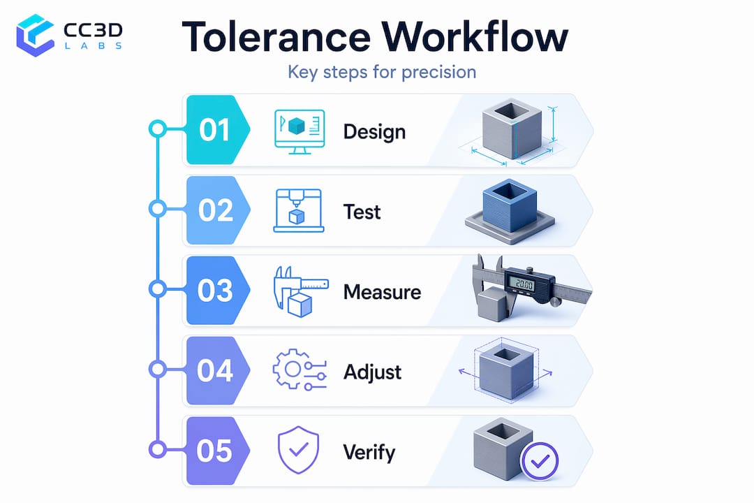
Infographic outlining 3D printing tolerance workflow steps


The tolerance conversation nobody has early enough

Here is something that does not appear in machine spec sheets: most dimensional problems in 3D printed assemblies are not printing problems. They are design problems that printing makes visible.

When a part does not fit, the instinct is to blame the printer. But in most cases we see, the designer never actually defined what the tolerance needed to be. They assumed the printer would handle it, the same way you might assume a contractor knows to leave room for drywall before framing a doorway. Printing does not assume. It builds exactly what you give it, within the spread the process allows.

The engineers who get the best results from additive manufacturing are the ones who treat tolerance as a design input, not a post-print concern. They decide early whether a feature needs a clearance fit or a press fit. They orient parts before slicing, not after getting poor results. They run test coupons the way a machinist cuts a test bar before touching the production stock.

Our experience working with product developers across industries around Philadelphia has shown that a single tolerance review session before the first print can eliminate two or three revision cycles. That is not a minor efficiency. On a compressed development schedule, two revision cycles can be the difference between hitting a launch window and missing it.

Treat tolerances the way you treat material selection: decide early, document clearly, and verify before you scale.


Precise 3D printing services at CC 3D Labs

Understanding tolerances is only half the equation. The other half is working with a printing partner who can actually hold them.

https://cc3dlabs.com

At CC 3D Labs near Philadelphia, we work directly with product developers and engineers on prototype and production parts where dimensional accuracy is not negotiable. We bring process expertise, not just machines, to every order. Whether you need tight-tolerance functional components, multi-material assemblies, or design support before your first print, we can help you get from CAD to a part that fits. Request a free online estimate or reach out to discuss your tolerance requirements directly with our team at cc3dlabs.com.


Frequently asked questions

What tolerance can I expect from standard FDM 3D printing?

FDM tolerances are approximately ±0.5% or ±0.5 mm minimum, with XY dimensions holding tighter than Z due to layer height limitations. In practice, well-calibrated FDM machines with consistent process control can achieve ±0.3 mm on small features.

How should I design fits for 3D printed parts to assemble properly?

Design intentional clearances based on fit type: clearance fits use roughly 0.3 mm gap per side, transition fits around 0.1 mm, and interference fits require a small intentional overlap with careful material and shrinkage consideration, especially in FDM where bore dimensions often print smaller than nominal.

Why are XY tolerances generally better than Z in 3D printing?

The XY axes benefit from continuous motion and higher mechanical resolution, while Z precision is bounded by the discrete layer height, meaning a 0.2 mm layer cannot meaningfully resolve finer Z increments regardless of the printer’s other specs.

Can tight tolerances be achieved with post-processing?

Yes. Features requiring tolerances tighter than ±0.05 mm often need CNC machining or reaming after printing. A common approach is to print with 0.3 to 0.5 mm of extra stock on critical surfaces, then machine to final dimension.

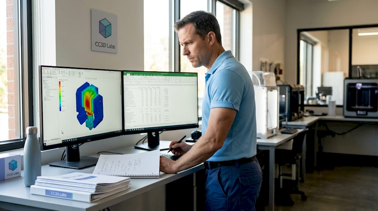
Engineer reviewing 3D CAD model in office

Top ways to validate 3D designs for reliable manufacturing


TL;DR:

  • Sending a flawed design file to production can lead to costly rework, missed deadlines, and scrapped parts.
  • Thorough 3D design validation, including geometry checks and reliable simulations, is essential before manufacturing begins.

Sending a flawed design file to production is one of the most expensive mistakes a product developer can make. A single overlooked wall thickness issue, a misapplied boundary condition in your simulation, or an ignored build orientation effect can mean scrapped parts, missed deadlines, and rework costs that eat straight into your project budget. Thorough 3D design validation is not a luxury step you add when time allows. It is the structured process that stands between a confident manufacturing run and a costly surprise. This article breaks down the most reliable methods to validate your designs before a single layer is printed.

Table of Contents

Key Takeaways

Point Details
Check early in CAD Surface deviation and wall thickness checks in CAD catch errors before prototyping.
Validate simulations rigorously Use mesh convergence, realistic materials, and compare with tests to ensure credible results.
Consider AM process effects Allow for part orientation and build location, as they directly impact final part accuracy.
Compare validation methods Use a mix of geometry, simulation, and manufacturing-focused checks for best outcomes.
Physical measurement trumps theory Always confirm with real-world testing before committing to mass production.

Check essential geometry and manufacturability constraints

With validation’s value established, let’s start at the CAD level, the foundation for reliable prototypes and parts.

Most design failures originate in the CAD file, not on the production floor. When you export a model that has non-manifold geometry, tiny gaps in surface meshes, or features too small for your target process to resolve, you are essentially shipping a problem downstream and paying someone else to find it. The good news is that modern CAD platforms give you tools to catch these issues before they travel anywhere.

Geometry validation early means checking surface deviation from reference geometry, confirming minimum wall thickness, and identifying features that the manufacturing process physically cannot produce. This applies to both subtractive machining and additive processes, but the specific thresholds vary. For FDM printing, a wall thinner than one nozzle diameter simply will not print. For SLS, fine lattice features below roughly 0.8 mm may fuse or collapse depending on the material and machine.

Key manufacturability constraints to check before you finalize any design:

  • Minimum wall thickness: Confirm walls meet your process’s minimum. For most FDM machines using a 0.4 mm nozzle, the minimum is roughly 1.2 mm for structural walls.
  • Unsupported overhangs: Overhangs beyond 45 degrees in FDM need support material. Designing to reduce support dependency saves post-processing time and surface quality issues.
  • Sharp interior corners: Stress concentrates at sharp internal corners. Radius them to at least half the wall thickness for functional load-bearing parts.
  • Detail resolution: Features smaller than the process resolution will not reproduce accurately. Embossed text, snap features, and thread starts are common failure points.
  • Mesh integrity: Export your STL or 3MF file and run it through a mesh repair check. Holes, inverted normals, and non-manifold edges cause slice errors that silently degrade part quality.

If you are working on parts where dimensional precision matters, review our guide to designing reliable 3D prints before finalizing your CAD. And if measurement validation is part of your workflow, the 3D scanning checklist walks you through exactly what to capture from physical parts for comparison.

Pro Tip: Set up automated geometry health checks in your CAD environment or through a dedicated add-on. Running these checks every time you export a file takes less than a minute and catches issues that manual review misses during long sessions.

For teams pursuing manufacturing-grade 3D printing, geometry validation is not optional. It is the baseline that every downstream step depends on.

Apply rigorous simulation validation steps

Geometric checks are necessary, but design validation reaches a new level with reliable simulation. Here’s how to ensure your virtual results reflect real-world performance.

Technician reviewing simulation results for 3D part

Running a finite element analysis (FEA) or computational fluid dynamics (CFD) simulation is only useful if the results are trustworthy. Many development teams make the mistake of treating simulation output as ground truth without verifying that the model itself is credible. A simulation built on incorrect boundary conditions or an under-resolved mesh will give you precise numbers that are completely wrong.

FEA credibility steps include mesh convergence studies, sensitivity analysis, realistic boundary conditions, accurate material properties, and comparison with experimental or analytical data. Follow this numbered sequence for every critical simulation run:

  1. Define realistic boundary conditions. Model how the part is actually constrained and loaded in service. A fixed-wall assumption when the real mount allows slight rotation will overestimate stiffness by a significant margin.
  2. Assign accurate material properties. Use measured data for the specific material grade and print orientation you are targeting. Published datasheet values are starting points, not substitutes for validated material cards.
  3. Run a mesh convergence study. Refine the mesh in stages and track your key output (peak stress, deflection, etc.). When refining the mesh further changes results by less than 5%, you have reached convergence.
  4. Perform sensitivity analysis. Vary your key inputs by a realistic uncertainty range. If small changes in your material inputs swing the predicted stress dramatically, you need better material data before trusting the result.
  5. Compare to a benchmark. Where possible, validate at least one simulation case against a physical test, a hand calculation, or a well-documented analytical solution.

For CFD work, the validation logic is similar but the pre-flight checks differ. CFD boundary layer resolution requires verifying the correct flow regime through Reynolds and Mach number checks, applying consistent and physically realistic boundary conditions, and resolving the near-wall region with appropriate boundary layer meshing. Getting the y+ value wrong in a turbulent flow case can produce drag and heat transfer predictions that are far off from measured values.

“Simulation-to-reality confidence is earned, not assumed. Every result needs a credibility trail, and that trail starts with the inputs.”

Pro Tip: Before signing off on any design validation package, physically benchmark at least one simulation case. Print a test part, measure it, load it to failure or measure pressure drop, and compare to your model. One confirmed data point is worth far more than ten unverified simulation runs.

For a process-level view of how simulation fits into production prep, check our step-by-step 3D printing guide and our overview of simulation validation best practices tied to physical part measurement.

Account for additive manufacturing-specific accuracy factors

After simulation, consider how manufacturing realities introduce new sources of variation, especially in additive processes.

Here is something many engineers underestimate: a perfectly designed CAD file and a validated simulation do not guarantee dimensional accuracy in the final printed part. Additive manufacturing introduces process-specific variation that exists entirely outside of your digital model. Build orientation, thermal gradients during the print cycle, and where the part sits inside the build chamber all affect the dimensions you will measure on the finished part.

Research on PA12 SLS parts shows that build orientation and chamber position measurably affect dimensional outcomes in ways that nominal CAD dimensions cannot predict. Parts built vertically may exhibit different shrinkage behavior compared to parts built horizontally, and parts at the chamber periphery often differ from those at the center due to thermal variation during the sintering cycle.

Practical methods for measuring and compensating for these effects:

  • Print calibration test artifacts. Before committing to a full production run, print a calibration coupon that includes representative features from your design: bosses, holes, flat spans, and slots. Measure these with calipers or, for critical parts, a coordinate measuring machine (CMM) or 3D scanner.
  • Document orientation-dependent deviation. Keep a log of how your machine and material combination behaves at different orientations. This becomes a design correction database over time.
  • Apply dimensional compensation offsets. If your CAD hole is consistently undersized by 0.15 mm after printing, adjust the nominal dimension to compensate. This is standard practice in professional AM workflows.
  • Account for anisotropy in functional parts. Mechanical properties vary by build axis in FDM and SLS. A part loaded along the Z axis (layer stacking direction) will be weaker than one loaded in XY. Design and validate accordingly.
Feature type Build orientation effect Chamber position effect Typical deviation range
Circular holes Moderate (XY vs. Z) Low to moderate 0.05 to 0.25 mm
Flat spans Low Moderate (center vs. edge) 0.03 to 0.15 mm
Vertical walls High Low 0.10 to 0.30 mm
Thin features High Moderate 0.10 to 0.40 mm

For teams focused on ensuring 3D print accuracy, tracking these variables is not optional. It is the difference between parts that fit and parts that need rework. Our low-volume 3D printing tips cover how to integrate these checks into short-run production workflows without slowing your schedule.

Summary table: Comparing key 3D design validation methods

With the main validation methods explained, a side-by-side comparison clarifies which approaches to prioritize.

Validation method Speed Reliability Required tools Best project stage
Geometry and manufacturability checks Very fast High for CAD-level issues CAD software, mesh repair tools Early design, pre-export
FEA simulation Moderate High if properly credentialed FEA solver, material data Detailed design, pre-prototype
CFD simulation Slow to moderate High with correct setup CFD solver, meshing tools Detailed design, thermal/flow parts
AM-specific dimensional validation Moderate Very high for process accuracy Calipers, CMM, 3D scanner Pre-production, first article
Physical benchmark testing Slow Definitive Test equipment, prototype parts Final design sign-off

The key insight from this comparison is that no single method covers all failure modes. Geometry checks are fast but tell you nothing about structural performance. FEA tells you about stress but not about how your machine will place those features in real space. Physical benchmarking is the most reliable but the slowest and most expensive. The winning strategy is to use these methods in sequence, using each one to reduce the risk that reaches the next stage.

Perspective: Why real-world validation always beats theoretical checks

Here is the uncomfortable reality that experienced product engineers know but rarely put in writing: digital validation is a filter, not a guarantee. CAD geometry checks and even well-credentialed simulations operate on idealized models. They assume uniform material properties, perfectly constrained geometry, and conditions that match whatever you entered into the model. The physical world does not honor those assumptions.

We have seen parts pass every simulation check, print cleanly, and then fail in assembly because a surface finish tolerance was tighter than the process could consistently hold. We have seen FEA results predict deflection within 2% of measured values, and then watched the same design crack at a feature that the mesh resolution had quietly smoothed over. These are not rare edge cases. They are predictable consequences of relying too heavily on theoretical validation.

The teams that consistently avoid manufacturing surprises do something deliberate: they treat digital checks as risk reduction tools and physical testing as risk confirmation tools. They run geometry checks and simulation early because it is cheap to catch errors at that stage. But they never skip the physical benchmark, even when the simulation looks clean. That benchmark might be a single printed part measured with a 3D scanner, or a simple load test on a coupon. The point is to introduce real-world data before the design is locked.

“Every model is a simplification. The question is whether your simplification preserved the physics that matter.”

The hidden gap between theory and practice is widest in additive manufacturing because the process itself introduces so many uncontrolled variables: ambient temperature, humidity, batch variation in powder or filament, and cumulative machine wear. A design validated purely in CAD and simulation may perform perfectly in batch one and show drift in batch three. Integrating physical measurement into your validation loop, even periodically, catches this drift before it becomes a field problem.

Our perspective, built from working with product developers across industries, is this: invest in digital tools, use simulation rigorously, but never mistake sophistication for certainty. The guide to manufacturing-grade 3D printing we put together reflects this philosophy. Physical results close the loop that theory opens.

Get expert support for validating your 3D designs

Validation is most valuable when it combines structured digital checks with hands-on manufacturing experience. At CC 3D Labs, near Philadelphia, we work with product developers and engineers at every stage of the design-to-production cycle, from reviewing CAD files for printability to producing first-article parts for dimensional inspection.

https://cc3dlabs.com

Our 3D printing services include design review, rapid prototyping, and professional handheld 3D scanning (accuracy to ~0.1 mm) that supports real-world dimensional validation. If you need to move from a validated simulation to a physical part fast, our on-demand prototypes are produced with tight tolerances and full traceability. For teams working through material selection and process setup, the custom filament printing guide covers exactly what you need to know before your first production run. Reach out for a free estimate and let’s put your design through its paces before it reaches the production floor.

Frequently asked questions

What is the first step in validating a 3D design?

Start with geometry and manufacturability checks in your CAD software to identify surface deviations, thin walls, and feature resolution issues before prototyping. This is the fastest and cheapest place to catch errors.

Why is simulation validation important before physical prototyping?

Credible simulation, built with mesh convergence and realistic inputs, gives you confidence that your design will perform as intended and avoids rework costs from unexpected structural or thermal failures.

How can I improve the accuracy of 3D printed parts?

Build orientation and chamber position both influence final part dimensions in additive manufacturing, so accounting for these variables and applying measured compensation offsets produces more accurate outcomes.

What makes a simulation “credible” for design validation?

A credible simulation includes mesh convergence, sensitivity analysis, accurate material properties, and at least one comparison to experimental data or a verified analytical solution before it can be used for design sign-off.

Engineer overseeing 3D prototype printing process

How 3D Printing Accelerates Design for Faster Prototyping


TL;DR:

  • Modern 3D printing reduces prototyping costs by up to 90% and speeds lead times from weeks to days.
  • Rapid iteration with 3D printing enables early testing, reduces risks, and improves team communication.
  • Combining in-house and outsourced 3D printing strategies enhances design flexibility and functional quality.

Prototyping has a reputation problem. Most engineers still think of it as the slow, expensive phase where momentum dies and budgets bleed out. But that assumption belongs to a different era. Modern 3D printing has rewritten the math entirely, cutting prototype costs by 50-90% compared to traditional CNC machining and collapsing lead times from weeks down to a matter of days. This article breaks down the real mechanics behind that shift, how to apply it across your workflow, and where most product teams still leave speed and money on the table.

Table of Contents

Key Takeaways

Point Details
Speed up prototyping 3D printing reduces prototype lead times from weeks to days for faster feedback.
Cut iteration costs Switching to 3D printing can slash per-iteration costs by up to 90%.
Choose the right workflow Hybrid workflows leverage both rapid 3D printing and validation with traditional techniques for optimal results.
Validate early and often Regular testing and empirical tolerance checks ensure functional and reliable designs using 3D printing.
Material matters Selecting the correct material and process is essential for turning prototypes into production-ready parts.

How 3D printing transforms the speed of design

Speed in prototyping used to mean cutting corners. With 3D printing, it means eliminating the steps that never added value in the first place.

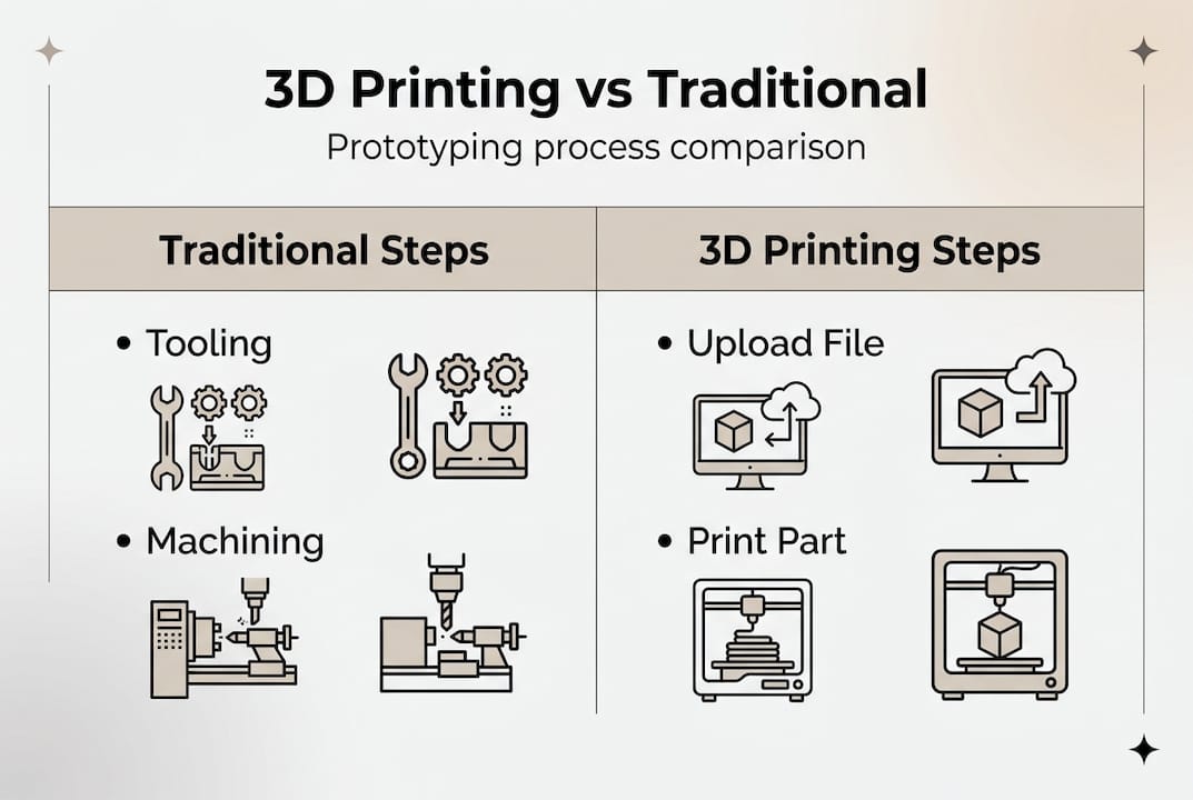
Traditional manufacturing requires tooling. Before a single part can be made, molds need to be designed, machined, and tested. That process alone can take two to four weeks and cost thousands of dollars before a designer even holds a physical prototype. Then if the design has a flaw, the process starts over. 3D printing removes that entire layer. Once your CAD file is ready, the printer starts. No molds, no setups, no waiting on a machine shop.

The empirical data backs this up clearly. Industry benchmarks show a 63% average lead time reduction from Wohlers Associates, a 70% cut in iteration costs documented by PwC, and Ford Motor Company reporting a 90% reduction in the time needed to produce physical models for new vehicle components. These are not outliers. They reflect what well-integrated 3D printing looks like across industries.

The industries feeling this most sharply include automotive, consumer electronics, medical devices, and aerospace, where rapid design cycles directly determine whether a product reaches market ahead of competition or behind it. Consumer product teams that once needed three weeks per prototype iteration now run through four or five cycles in the same time window.

Below is a quick snapshot of what the before and after looks like for a typical product team:

Metric Traditional process With 3D printing
Prototype lead time 2 to 6 weeks 1 to 5 days
Cost per prototype $2,000 to $10,000+ $50 to $500
Iteration cycles per month 1 to 2 6 to 10
Design change turnaround 2 to 3 weeks Same day to 48 hours
Tooling cost $5,000 to $50,000 None

Key advantages that drive these numbers include:

  • No tooling or setup costs between design changes
  • Files go straight from CAD to build platform
  • Multiple design variants can print simultaneously overnight
  • Complex geometries print without additional cost or machining complexity
  • Short runs and one-off parts are economically viable

If you want a structured look at how this fits into a full product development strategy, the rapid prototyping guide covers the foundational principles in depth. For teams that need parts fast without sacrificing quality, fast turnaround 3D printing is the practical application of these principles. External manufacturing cost-saving methods also show how 3D printing fits into broader efficiency strategies beyond just prototyping.

The design iteration advantage: Rapid cycles and instant feedback

After seeing how the numbers measure up, it is important to understand how this process transforms the workflow of real product development teams, especially when fast, iterative changes are on the line.

The single biggest workflow change 3D printing delivers is not speed. It is the freedom to be wrong earlier and more cheaply. When a prototype costs $8,000 and takes four weeks, teams hedge their bets. They over-engineer designs on paper, delay physical testing, and often discover fundamental flaws only after significant resources are committed. When a prototype costs $80 and takes 24 hours, the psychology shifts completely. Testing becomes routine rather than a milestone.

Consider a typical day in the life of a design team using 3D printing compared to one relying on traditional methods:

  1. Morning design review. The team identifies a clearance issue in the assembly fit from yesterday’s print. A designer opens the CAD file and adjusts the tolerance by 0.3mm.
  2. File prep and submission. The updated file is sliced, reviewed for printability issues, and sent to the printer by 10 AM.
  3. Print runs during the day. The printer runs unattended while the team works on other components or adjacent design problems.
  4. Afternoon evaluation. The new part is ready by mid-afternoon. The team fits it into the assembly, confirms the fix works, and identifies the next issue to address.
  5. Overnight print queued. A further refined version, incorporating all of today’s findings, is queued to run overnight.
  6. Next morning. The team arrives to a finished part and repeats the cycle.

Without 3D printing, step one would trigger a new quote request, a lead time negotiation, and a wait period measured in weeks rather than hours. The cost gap between methods is equally stark: traditional CNC prototyping can cost 5 to 20 times more per iteration, which limits how many cycles a team can run within a fixed budget.

Here is a direct comparison of iteration cycles:

Factor Without 3D printing With 3D printing
Change to physical part 2 to 4 weeks 1 to 48 hours
Typical industry cost per iteration $1,000 to $10,000+ $20 to $300
Risk of catching flaws late High Low
Team feedback loops Monthly Daily
Cross-functional testing speed Slow Fast

Pro Tip: Use in-house desktop FDM (Fused Deposition Modeling) or SLA (Stereolithography) printers for rapid, low-risk design iterations on geometry and fit. Reserve outsourced SLS (Selective Laser Sintering) or DMLS (Direct Metal Laser Sintering) for functional prototypes that need near-production material properties. The cost difference is significant and the distinction saves time where it matters most.

For teams who want to build physically reliable parts from the start, designing for reliable 3D prototypes is the right starting point before any iteration cycle begins.

Integrating 3D printing with traditional manufacturing

Now that rapid iteration is clear, the crucial question for engineers is how and when 3D printing best fits into the broader manufacturing toolbox.

3D printing is not a replacement for every manufacturing process. It is a precision tool for specific phases and applications, and misapplying it creates its own set of problems. The teams that get the most value are the ones who know exactly when to use it and when to hand off to traditional methods.

Hybrid strategies represent the most effective approach: use 3D printing for early concepts, design exploration, and complex geometries, then transition to CNC machining or injection molding for validation, durability testing, and production-scale parts. This approach captures speed in the phase where speed matters most, without sacrificing the material strength and tolerances that validated production parts require.

Infographic comparing 3D printing and traditional prototyping steps

Here is a practical breakdown of when to choose each approach:

Use 3D printing when:

  • You need a physical prototype within 24 to 72 hours
  • The geometry is too complex for traditional machining
  • You are running low-volume custom parts (under 100 units)
  • You need to test form, fit, or basic function before committing to tooling
  • Design is still in flux and changes are expected

Use CNC machining or injection molding when:

  • You need tight tolerances under 0.05mm for functional assemblies
  • Parts must withstand high mechanical loads or thermal stress
  • You are producing more than 500 units of the same design
  • Surface finish requirements exceed what FDM or SLA can deliver
  • Material certification is required (aerospace, medical implants)

Pro Tip: Build a deliberate handoff point into your development process. Define upfront which prototype generation marks the transition from 3D printing to traditional manufacturing. Many teams delay this handoff too long, running 3D printed parts through stress tests that expose limitations of the process rather than the design.

Always validate tolerances empirically before assuming a design is production-ready. No simulation and no print specification replaces a physical measurement on a calibrated instrument.

Teams looking to apply these principles at low volume will find low-volume 3D printing tips directly useful, while manufacturing-grade 3D printing covers what it takes to push printed parts closer to production quality. The production optimization guide offers complementary strategies for integrating additive methods across the broader manufacturing pipeline.

Maximizing reliability: Print accuracy, material selection, and quality control

To unlock the full potential of 3D printing within your workflow, reliability and quality must be part of every step, not an afterthought after the print is done.

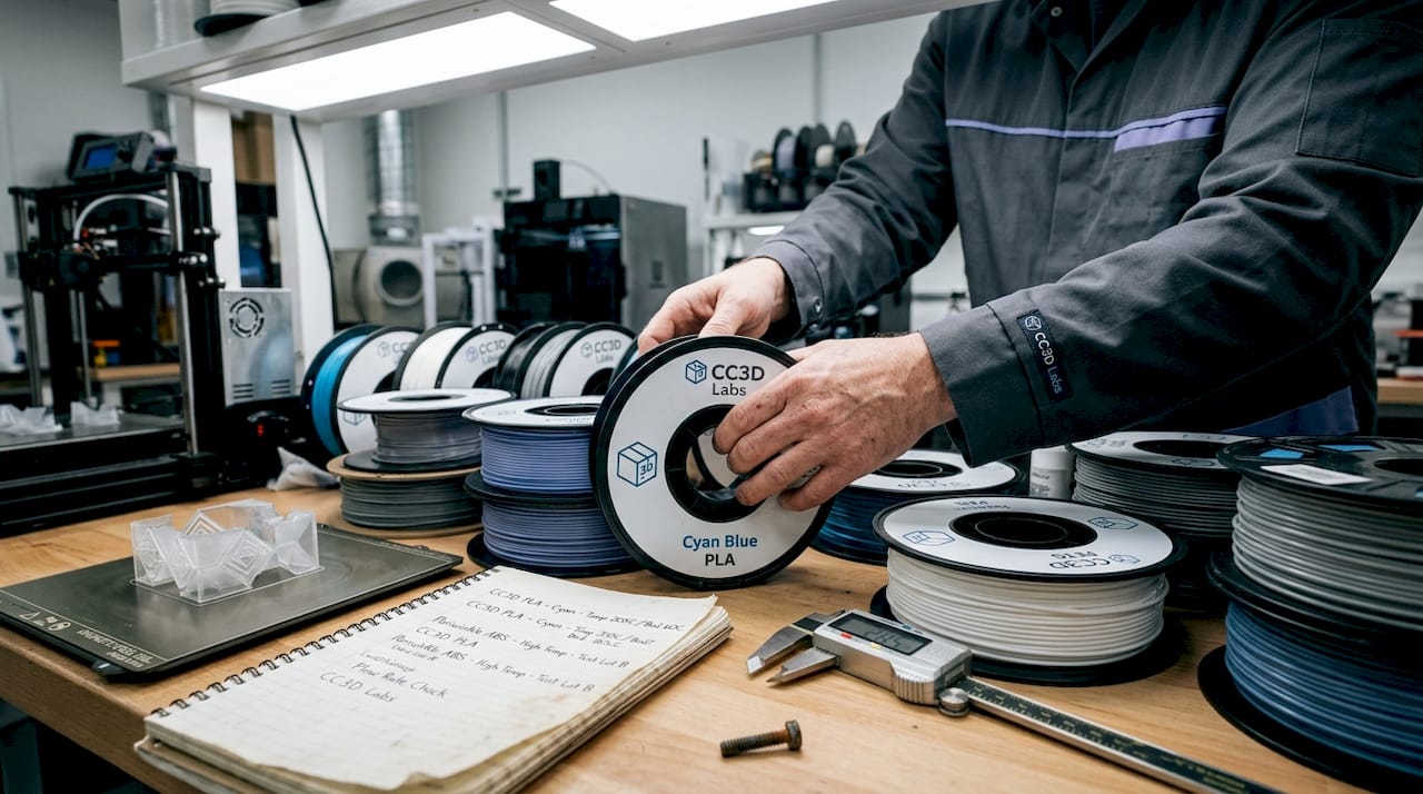
Material selection is the first decision that determines whether a printed part performs or fails. PLA (Polylactic Acid) is fine for concept models and visual prototypes where loads are minimal. PETG (Polyethylene Terephthalate Glycol) brings better impact resistance and heat tolerance, making it suitable for light functional parts. ASA and ABS handle UV exposure and higher temperatures. For truly functional parts requiring near-engineering-grade properties, Nylon, Polycarbonate, or composite filaments with carbon fiber or glass fill are the right materials. Metal printing via DMLS delivers the closest properties to machined metal, but at a significantly higher cost per part.

Lab specialist handling various 3D print filaments

Accuracy requires attention at the design stage, not just the print stage. Wall thickness, support structures, bridging distances, and orientation all affect dimensional accuracy. A part that looks perfect in CAD can print with 0.5mm of warp if support strategy and material shrinkage are not factored in before slicing.

Empirical validation of tolerances is non-negotiable, particularly for assemblies with mating parts. Prioritize in-house FDM or SLA for iterative design work, and outsource SLS or DMLS when functional prototypes demand tighter tolerances and superior surface quality.

Follow these steps to ensure your printed parts are reliable before scaling up:

  1. Define the functional requirements first. Determine what loads, temperatures, and fits the part must survive before selecting a material or process.
  2. Design for printability. Review wall thickness minimums, avoid unsupported overhangs beyond 45 degrees, and design in clearance where mating parts will interface.
  3. Validate the print setup. Run a test print of a critical feature or cross-section before committing to a full build.
  4. Measure, not just visually inspect. Use calipers or a CMM (Coordinate Measuring Machine) to verify critical dimensions against your CAD model.
  5. Test under real conditions. Fit the part into its assembly, apply representative loads, and confirm behavior before declaring the design ready for the next phase.
  6. Document what worked. Record print settings, material lot, and measured results so you can reproduce the outcome reliably for future builds.

Pro Tip: Never skip design validation before scaling up production quantities. A single print defect that passes visual inspection can become a systematic failure across a batch of 200 parts. Measure first, scale second.

For more on the variables that affect dimensional output, print accuracy for prototyping is a detailed resource on what to control and how.

Why most teams underestimate the true impact of 3D printing

Here is an observation worth sharing directly: most conversations about 3D printing in product development focus on speed and cost savings, as they should. But those are just the most visible benefits. The less obvious and arguably more important impact is what 3D printing does to how teams communicate and make decisions.

When you put a physical prototype on a table during a cross-functional review, something changes. Marketing, manufacturing, QA, and leadership all engage differently with a real object than with a render or a drawing. Feedback becomes concrete. Objections get raised earlier. The kinds of misunderstandings that survive three rounds of 2D documentation rarely survive five minutes with a physical model.

The teams that get the most from 3D printing are not necessarily the ones with the most advanced printers. They are the ones who have built a culture where physical prototyping is routine and expected at every stage of design. They use what their 3D printer can produce not just to test parts but to communicate intent, to challenge assumptions, and to filter out costly mistakes before tooling and capital are on the line.

The conventional framing treats 3D printing as a cost center to be optimized. The more accurate framing treats it as a risk management tool that pays for itself by catching problems at the cheapest possible moment in the development cycle. A $150 print that exposes a fundamental design flaw is worth more than a $15,000 tooling revision that fixes the same problem six months later.

Hybrid approaches, combining desktop FDM or SLA in-house with outsourced SLS or DMLS for functional builds, consistently outperform single-method strategies. But even the best hybrid strategy delivers only part of its potential if the human element is missing. Designer intuition, shop floor experience, and direct stakeholder feedback are not replaced by technology. They are amplified by it.

Accelerate your next design project with expert 3D solutions

Understanding the principles is only the first step. Putting them into practice with the right equipment, materials, and process expertise is where results actually show up.

https://cc3dlabs.com

CC 3D Labs near Philadelphia offers professional 3D printing services built specifically for product developers and engineering teams who need reliable, high-quality results under real project timelines. Whether you need a single concept prototype or a batch of functional parts, the 3D printing on demand service gets your design from file to physical part fast. If you are still scoping what is possible, exploring 3D printing applications shows the full range of what modern filament-based printing can produce for functional, production-grade, and custom needs. Request a free estimate and move your design forward.

Frequently asked questions

How much faster can iterative design cycles be with 3D printing?

Lead times for prototypes can drop from several weeks to as little as 1 to 5 days, enabling up to 63% faster average cycles across the product development process.

Is 3D printing better than CNC machining for all types of parts?

3D printing is the stronger choice for early prototypes and complex geometries, but CNC is preferred for high-strength requirements, tight tolerances, and validated production parts where material properties are critical.

What is the main limitation of using 3D printing in product design?

Material strength and surface finish can lag behind traditional manufacturing, which is why empirical validation of tolerances is essential before any functional prototype moves into production consideration.

Should startups buy a 3D printer or outsource their prototyping?

In-house desktop printers handle rapid, low-cost design iterations well, but outsourcing SLS or DMLS delivers better results for functional, high-precision prototypes that need near-production material performance.

Designer working on 3D model at home workspace

What Is 3D Art Design? Key Concepts for Prototyping


TL;DR:

  • 3D art design combines visual appeal with functional geometry for manufacturable prototypes.
  • Successful printing relies on proper technical parameters, validation, and iterative testing.
  • Integrating artistic judgment, engineering, and manufacturing awareness ensures high-quality, print-ready models.

Most businesses treat 3D art design as a visual exercise — something you do to make a product look good on screen before handing it off to engineering. That assumption costs time, money, and failed prints. Vital role in prototyping is what separates teams that iterate fast from those stuck in endless revision cycles. This guide breaks down what 3D art design actually means for product developers, how the workflow runs from concept to print-ready file, which technical parameters determine real-world part performance, and what pitfalls to avoid before you ever load a spool of filament.

Table of Contents

Key Takeaways

Point Details
3D art design explained It integrates creativity with engineering to turn digital models into printable, functional objects.
Workflow matters Using the right mix of CAD and AI tools ensures designs are accurate and ready for manufacturing.
Technical choices drive quality Infill density, layer height, and geometry corrections greatly influence prototype strength and print success.
Fix design errors early Address issues like thin walls and non-manifold geometry in the design phase to avoid costly print failures.

Defining 3D art design: Purpose and scope

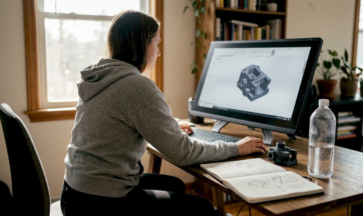
Strip away the aesthetics conversation and 3D art design becomes something very precise: it is the discipline of creating digital three-dimensional geometry that serves both visual and functional goals. Unlike a 2D illustration or a rendered product concept, a 3D art design file carries spatial data — wall thickness, internal geometry, surface topology — that directly controls how a physical object gets manufactured.

For businesses and product developers, the distinction matters enormously. A designer who only thinks in terms of appearance will produce files that look stunning in a render and fail catastrophically on the print bed. A developer who only thinks in terms of engineering tolerances may produce parts that are accurate but lack the surface quality or aesthetic cohesion needed for a marketable prototype. The strongest 3D art designs sit at the intersection of both.

3D art design translates creative and engineering concepts into digital files ready for custom 3D printing and manufacturing. That translation process is where most of the real work happens — converting a sketch, a scan, or an idea into a watertight mesh that a slicer can process without errors.

Here is what 3D art design actually produces in a business context:

  • Product prototypes: Functional mockups that test form, fit, and mechanical behavior before committing to tooling
  • Artistic fabrication parts: Custom sculptures, branded objects, or decorative components with precise dimensional accuracy
  • Engineering mockups: Assembly verification models that confirm spatial relationships between components
  • Batch production masters: Reference parts used to validate consistency across a production run

“The digital model is not the end product — it is the manufacturing instruction. Every decision you make in the design file shows up in the finished part.”

You can see how these outputs look in real applications by browsing our 3D modeling gallery, which shows the range of projects that move from digital concept to physical prototype. Understanding the vocabulary behind these workflows also helps — getting familiar with 3D printing terminology early prevents costly miscommunications between designers and print technicians.

Core workflows in 3D art design: From idea to printable model

Once you know what 3D art design is, the next step is understanding how ideas turn into print-ready files. Here is how modern businesses convert concepts to physical parts.

The standard workflow follows four stages:

  1. Ideation and reference gathering: Sketches, reference images, scan data, or engineering specifications define the geometry constraints and aesthetic intent before any software opens.
  2. Modeling and geometry construction: Either parametric CAD software or mesh-based sculpting tools (including AI-assisted platforms) are used to build the 3D geometry. This is where file quality diverges sharply based on tooling choices.
  3. Validation and mesh repair: The model is checked for printability errors — non-manifold geometry, inverted normals, open surfaces. Any issues get resolved before export.
  4. File preparation and export: The clean model exports as STL, OBJ, or 3MF depending on the print service’s requirements. 3MF is increasingly preferred because it carries color, material, and unit data inside a single file.

The biggest decision point sits at step two: AI-assisted tools versus parametric CAD.

Feature AI tools (e.g., Meshy, Wonder3D) Parametric CAD (e.g., Fusion 360)
Speed of ideation Very fast Moderate
Dimensional accuracy Low to moderate High
Mesh quality Often error-prone Clean and watertight
Editing flexibility Limited Full parametric control
Best use case Concept exploration Production-ready prototypes

AI tools accelerate ideation but often create error-prone meshes needing CAD repair for printability. Parametric CAD tools like Fusion 360 remain superior for precise prototypes because they build geometry from defined constraints rather than interpolated surface data.

Engineer reviewing 3D mesh repair tools

For businesses, the practical answer is often a hybrid approach: use AI tools to generate a fast concept, then rebuild critical geometry in CAD for accuracy.

Pro Tip: Always run your STL file through a mesh repair tool like Meshmixer or Netfabb before submitting it for printing. Even CAD-generated files can develop small errors during export that cause slice failures.

Understanding print accuracy for prototypes before you finalize your file saves significant rework time. A step-by-step 3D printing workflow that accounts for file validation at each stage dramatically improves first-print success rates.

Essential technical factors: What makes a design printable and strong

Understanding the workflow is half the story. For real prototype or product success, you need to master several technical details that have measurable, documented effects on print outcomes.

The parameters that matter most:

Parameter Effect on prototype Recommended range
Infill density Drives tensile, compression, and impact strength 20% to 60% for most functional parts
Layer height Controls surface roughness and Z-axis detail 0.1 mm to 0.3 mm
Wall thickness Determines shell rigidity and surface finish Minimum 1.2 mm for structural parts
Print orientation Governs anisotropic strength distribution Orient load-bearing axis away from Z

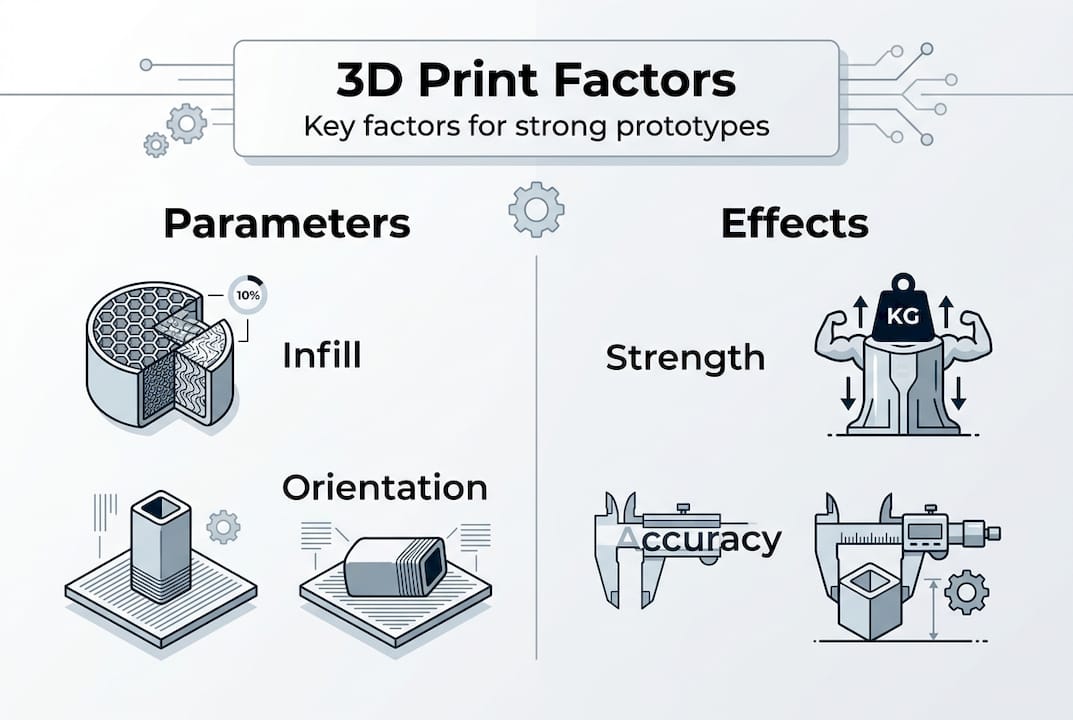
Infill density impacts tensile strength by 55%, compression strength by 81%, and impact strength by 64% in PLA. That is not a marginal difference — going from 20% to 60% infill is an engineering decision, not a print setting.

Infographic showing key 3D print design factors

Infill pattern also matters more than most teams realize. Gyroid infill boosts bending modulus 15 to 35% compared to honeycomb, making it the better choice for parts that will experience lateral load. Layer thickness affects both surface roughness and hardness. And Z-axis strength remains anisotropic — parts printed vertically are significantly weaker along their build direction than parts printed flat.

Common design mistakes that create problems:

  • Thin walls below 0.8 mm: The slicer may not generate any toolpath at all, leaving structural voids
  • Overhangs steeper than 45 degrees: Without support structures, these collapse during printing
  • Tolerances tighter than 0.2 mm: Material shrinkage and thermal expansion make sub-0.2 mm tolerances unreliable in FDM printing
  • Ignoring warping on large flat bases: Parts with large footprints need brim settings or material choices that resist bed separation

The good news is that all of these are preventable at the design stage. Resources on designing reliable prototypes and low-volume manufacturing tips give you specific geometry guidelines that catch these issues before manufacturing begins.

Design pitfalls and advanced solutions: Getting print-ready for custom parts

Even with the right technical setup, custom part designs can present tough edge cases. Here is how to address and solve them for a successful print.

The most common problem categories and their solutions:

  • Non-manifold geometry: Surfaces that share an edge or overlap internally confuse slicers. Fix with Meshmixer’s Inspector tool or Netfabb’s automatic repair. Always verify with a manifold check before export.
  • Thin walls and fragile features: Features below 1.2 mm wall thickness may not print cleanly. Add material to thin features or redesign with a minimum feature size that matches your nozzle diameter.
  • Sharp overhangs above 45 degrees: Add chamfers or fillets at transition points. A 1 mm to 2 mm fillet at a sharp edge reduces the overhang angle and eliminates the need for support material in most cases.
  • Shrinkage and warping on large parts: Choose materials with lower thermal expansion (like PETG over ABS for moderate-temperature applications) and include a brim in your slicer settings for large flat footprints.
  • Over-tight assembly tolerances: Design-in clearance gaps of at least 0.2 mm to 0.3 mm between mating parts. Test fit with a single-layer print of the mating interface before committing to the full print.
  • Draft angle omission: Parts designed for injection molding often lack draft angles, which causes adhesion problems on vertical walls during FDM printing. Add 1 to 2 degree draft angles to vertical faces wherever possible.

Non-manifold geometry, thin walls, sharp overhangs, and over-tight tolerances are the leading causes of print failure for custom parts. The fix in almost every case starts with catching the error in the file, not on the printer.

Pro Tip: Before submitting a complex prototype for full production, run a scaled-down test print at 50% size. This validates the geometry, support structures, and layer adhesion in a fraction of the time and material cost of a full-size print.

For unfamiliar geometry types or advanced material requirements, 3D printing jargon defined is a practical reference that clears up terminology confusion between design teams and print specialists. For parts that need to meet strict functional standards, exploring engineering-grade printing options ensures the material and process match the application.

Our perspective: Why mastering 3D art design means thinking beyond the model

Here is what most businesses and product teams miss when approaching 3D art design: a beautiful model is not a manufacturable product. We see it consistently — teams invest heavily in high-end rendering and visual design, then submit a file that fails the first slicer check because no one validated it against print constraints.

The uncomfortable truth is that 3D art design for prototyping requires three disciplines to work together: artistic judgment, engineering precision, and manufacturing awareness. Drop any one of them and your output quality drops. A stunning geometry that ignores layer adhesion mechanics will break under functional load. An accurate CAD file that ignores aesthetics produces a prototype nobody wants to show to stakeholders.

What separates successful teams is iterative, test-driven thinking. They design for the print process, not around it. They run test prints, measure results against specifications, and feed that data back into the next design revision. That loop — design, print, measure, revise — is where real innovation happens. Browsing best 3D print jobs gives you a reference point for what that discipline produces in practice.

How CC3DLabs can turn your design vision into reality

Ready to put world-class 3D art design to work for your business? At CC 3D Labs, we work with product developers and businesses near Philadelphia and across the country to transform high-quality 3D art designs into precise, functional prototypes and custom parts.

https://cc3dlabs.com

Our team handles everything from CAD validation and mesh repair to full-run production using advanced filament-based printing. Whether you need a single concept prototype or a batch of functional parts, our 3D printing services are built for accuracy and fast turnaround. Not sure what your design can produce? Explore what you can print to see the range of applications we support, or jump straight into print on demand to get your project moving with a free online estimate.

Frequently asked questions

What is the difference between 3D art design and regular 3D modeling?

3D art design combines artistic and engineering principles to produce geometry that is both visually resolved and manufacturable, while standard 3D modeling often targets digital-only assets without accounting for physical production constraints. 3D art design translates creative concepts directly into files ready for custom manufacturing.

Why do AI tools for 3D art design need CAD repair before printing?

AI-generated meshes commonly contain non-manifold geometry, surface gaps, and inverted normals that cause slicer failures. CAD repair tools rebuild the mesh structure to make the model watertight and dimensionally accurate. AI tools accelerate ideation but consistently require post-processing before any file is print-ready.

Which technical factor most affects the strength of 3D printed prototypes?

Infill density and print orientation have the greatest combined impact on prototype strength. Infill density impacts tensile strength by 55%, compression by 81%, and impact resistance by 64% in PLA, making it the single highest-leverage parameter in the slicer settings.

What common design pitfalls can ruin 3D print quality?

Thin walls below 0.8 mm, non-manifold geometry, overhangs above 45 degrees, and assembly tolerances tighter than 0.2 mm are the most frequent causes of failed or unusable prints. Non-manifold geometry, thin walls, and over-tight tolerances can all be caught and corrected during the design validation stage before manufacturing begins.