
TL;DR:
- Understanding and applying proper tolerances in 3D printing are essential for functional, accurately fitting parts, as printer technology, part size, and orientation significantly influence achievable precision.
- Designers must consider tolerance as a key early input, choosing appropriate clearance or interference fits, orienting critical features in the XY plane, and accounting for material behavior and shrinkage to ensure successful assembly.
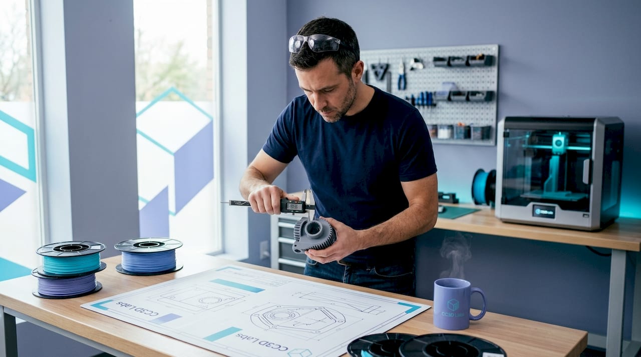
If you have ever printed a part from a perfect CAD model only to find it won’t snap together, rotates when it should be fixed, or gaps where it should seal, you already understand why tolerances in 3D printing are not optional knowledge. Tolerance is the designed allowance for dimensional deviation in a part, and every functional component you print lives or dies by how well you understand and apply it. This guide gives you the practical framework to design parts that actually work when they come off the build plate.
Table of Contents
- Understanding tolerances in 3D printing: accuracy, precision, and what actually matters
- How different 3D printing technologies impact tolerance capabilities
- Key factors influencing tolerances: size, orientation, and material behavior
- Designing for tolerances: best practices for precise 3D printed assemblies
- Assessing and verifying 3D printing tolerances: from machine specs to quality assurance
- The tolerance conversation nobody has early enough
- Precise 3D printing services at CC 3D Labs
- Frequently asked questions
Key Takeaways
| Point | Details |
|---|---|
| Tolerance vs accuracy | Tolerance is the allowed range of dimensional deviation; accuracy is how close a print is to the CAD model. |
| Technology choice matters | Different 3D printing methods offer varying tolerance capabilities impacting final part precision. |
| Design influences outcome | Part size, geometry, orientation, and material affect achievable tolerances and must be considered early. |
| Design for assembly | Use intentional clearances tailored to fit types and printing technology for functional parts. |
| Verify and measure | Assess vendor specs for bias and precision, and validate prints to ensure tolerances are met. |
Understanding tolerances in 3D printing: accuracy, precision, and what actually matters
These three terms get used interchangeably in shop conversations, and that confusion causes real problems at the design stage. Tolerance is the range of acceptable deviation designed into the part; accuracy measures how close the printed dimension is to your CAD model; and precision measures whether the printer reproduces that same dimension reliably across multiple prints.
Here is why the distinction matters in practice:
- Tolerance is a design decision. You set it in your CAD file based on what the part needs to do.
- Accuracy is a machine and process characteristic. A printer might consistently produce parts 0.2 mm undersize, which is a bias, not a random error.
- Precision is about repeatability. A precise printer gives you the same result every run, even if that result drifts slightly from nominal.
A printer can be precise but not accurate (it produces the same wrong dimension every time), or accurate on average but imprecise (results scatter around the target). For functional parts, you need both, and your tolerance band must be wide enough to accommodate whichever combination of bias and scatter your process exhibits.
For a broader orientation to how these concepts fit into the vocabulary of additive manufacturing, the 3D printing terminology explained resource at CC 3D Labs is worth bookmarking before you go further into process selection.
How different 3D printing technologies impact tolerance capabilities
Technology choice is your single biggest lever for dimensional control. The typical tolerance ranges vary significantly by process, as shown in the table below.
| Technology | Typical tolerance | Minimum tolerance |
|---|---|---|
| Carbon DLS | ±0.1% | ±0.1 mm |
| Polyjet | ±0.1 mm (first 10-20 mm) | +±0.05 mm per additional mm |
| DMLS | ±0.2% | ±0.1 to 0.2 mm |
| MJF | ±0.3% | ±0.2 mm |
| SLS | ±0.3% | ±0.3 mm |
| SLA | ±0.5% | ±0.2 mm |
| FDM | ±0.5% | ±0.5 mm |
A few things that table does not make obvious on its own:
- Percentage-based tolerances scale with part size. An MJF part at 200 mm carries ±0.6 mm of tolerance just from the percentage component, regardless of minimum value. For large structural components, that adds up fast.
- SLA trades resolution for material limitations. SLA can hold ±0.2 mm on small features beautifully, but photopolymers are sensitive to UV exposure after printing, which can cause post-cure dimensional drift if you are not controlling the process.
- FDM’s ±0.5 mm floor is non-negotiable for most off-the-shelf machines. You can improve on it with process control and calibration, but designing FDM parts that require ±0.1 mm without post-processing is setting yourself up for failure.
- DMLS and Carbon DLS are the precision leaders, but they require capital investment or premium service pricing that only makes sense when the application demands it.
Pro Tip: Make the technology decision before you finalize your CAD geometry, not after. Designing for SLA and then switching to FDM to cut cost almost always means a complete tolerance review of every mating feature.
If you are evaluating whether your project qualifies for tighter process control, the manufacturing-grade 3D printing guide at CC 3D Labs covers where the bar sits for production-intent parts.
Key factors influencing tolerances: size, orientation, and material behavior
Machine specs tell you the best-case scenario. Real parts live in a messier world where tolerances depend on part size, material, and geometry, and larger parts shrink more, warp differently, and require active compensation in your process.
Here is what to account for in your design and build planning:
- Part size and shrinkage. Polymers contract as they cool. A 10 mm feature might land within ±0.1 mm. That same shrinkage rate applied to a 150 mm span produces an error that can easily exceed your tolerance band without scaling compensation in the slicer or at the printer.
- Build orientation. This is one of the most underused variables in tolerance management. Orienting a mating surface parallel to the XY build plane can deliver up to 2x better dimensional accuracy than running that same surface vertically. The XY tolerances typically outperform Z tolerances across every major printing technology, and features under 25 mm achieve the tightest specs when kept within the XY plane.
- Z-axis limitation. Layer height directly sets a floor on Z precision. A 0.2 mm layer height means you cannot meaningfully hold a Z dimension to tighter than that layer value, regardless of what the machine spec sheet says.
- Material selection. Glass-filled PA12 (polyamide with glass fiber reinforcement) dramatically reduces the tolerance spread compared to standard nylon because it resists shrinkage anisotropy. Flexible TPU, by contrast, is nearly impossible to hold to tight tolerances because the material deforms under measurement pressure.
- Environment and process parameters. Bed temperature, chamber temperature, cooling rate, and print speed all affect dimensional consistency. In a production context, these variables should be locked and documented, not adjusted run to run.
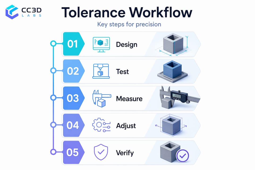
Pro Tip: Before committing to a full production run, print a set of test coupons that include your most critical mating features. Measure them with calipers or a CMM (coordinate measuring machine, a device that precisely maps part geometry), then apply dimensional offsets in your CAD or slicer before scaling up.
For a practical breakdown of how these variables play out in real prototype design, designing reliable 3D prints is a strong next read.

Designing for tolerances: best practices for precise 3D printed assemblies
Good tolerance design is not about chasing the tightest possible number. It is about matching your clearance strategy to the job the assembly needs to do. For FDM assemblies, design mating features with conservative ±0.3 mm tolerance; SLA features under 25 mm can achieve ±0.1 mm. Choose clearances based on fit type.
Here is a step-by-step approach to build tolerance intent into your design from day one:
- Classify each interface by fit type. Clearance fits (parts slide or rotate freely), transition fits (either slight clearance or slight interference), and interference fits (parts press together permanently) each require different gap values in your CAD model.
- Apply fit-specific clearances in CAD. For a sliding clearance fit in FDM, start with 0.3 mm per side. For a transition fit, try 0.1 mm. For a press fit in FDM, design for 0.05 to 0.1 mm interference and expect to test, because thermal and material properties vary.
- Orient critical surfaces in XY. The face that needs to mate, seal, or bear load should be parallel to the build plate wherever possible. This is the single cheapest accuracy improvement available.
- Design clearances in CAD to allow for shrinkage and warp, especially for large enclosed geometries. Slicer-level scaling can compensate for consistent shrinkage, but warping requires design changes like adding gussets or reducing flat, unsupported spans.
- Plan for post-processing on tight features. Any hole or bore that needs to hold better than ±0.1 mm is a candidate for drilling or reaming after printing, not relying on the printer alone. Bores printed to a nominal of 6.0 mm often measure 5.6 to 5.8 mm in FDM, which is a known, correctable bias if you plan for it.
- Document your tolerance intent in the drawing. Even for prototypes, marking which dimensions are critical prevents downstream confusion when a supplier or colleague reruns the file.
Pro Tip: If you are iterating quickly, use your slicer’s tolerance variable or scaling factor as a fast-tweak tool between test prints. You can dial in a consistent offset for your specific machine, material, and geometry combination without touching the master CAD file.
Additional guidance on making these decisions early in the design cycle is at print accuracy for prototyping and a broader collection of process pitfalls is covered in 3D printing challenges and pro tips.
Assessing and verifying 3D printing tolerances: from machine specs to quality assurance
Reading a vendor’s tolerance specification correctly is a skill most engineers never develop until a bad batch forces the lesson. Tolerance is a design property; machines have bias (a consistent directional error) and precision (the spread of results around that error). The two are independent, and both must fit inside your tolerance band before the process is capable.
Key points for evaluating process capability:
- Bias alone does not disqualify a process. If a machine consistently prints 0.15 mm undersize, you can compensate by offsetting your CAD geometry. What you cannot easily compensate is high scatter.
- Vendor specs often represent best-case geometry. A quoted ±0.2 mm spec may come from a small, simple, centrally located test artifact, not from your large, complex, corner-of-the-build-plate production part.
- Zone or quadrant data matters. Ask suppliers for dimensional accuracy data from different areas of the build volume. Edges and corners of a build plate frequently show worse performance than the center.
- Your tolerance band must be wider than the combined bias plus spread. If your design tolerance is ±0.3 mm and the process has a 0.1 mm bias and a ±0.25 mm scatter, you are operating with essentially zero margin.
| Metric | What it means | Practical implication |
|---|---|---|
| Bias | Consistent directional offset | Compensate in CAD scaling |
| Precision (spread) | Variability run to run | Sets minimum feasible tolerance |
| Acceptance criteria | Tolerance band from drawing | Must exceed bias + spread |
| Cpk (process capability) | Ratio of tolerance to process variation | Target Cpk above 1.33 for production |
Sampling and measurement are non-negotiable for anything moving toward production. Measuring every tenth part with calipers at minimum, and using a CMM or ensuring 3D print accuracy protocols for tighter-spec work, gives you the feedback loop needed to catch drift before it becomes a scrapped batch.
The tolerance conversation nobody has early enough
Here is something that does not appear in machine spec sheets: most dimensional problems in 3D printed assemblies are not printing problems. They are design problems that printing makes visible.
When a part does not fit, the instinct is to blame the printer. But in most cases we see, the designer never actually defined what the tolerance needed to be. They assumed the printer would handle it, the same way you might assume a contractor knows to leave room for drywall before framing a doorway. Printing does not assume. It builds exactly what you give it, within the spread the process allows.
The engineers who get the best results from additive manufacturing are the ones who treat tolerance as a design input, not a post-print concern. They decide early whether a feature needs a clearance fit or a press fit. They orient parts before slicing, not after getting poor results. They run test coupons the way a machinist cuts a test bar before touching the production stock.
Our experience working with product developers across industries around Philadelphia has shown that a single tolerance review session before the first print can eliminate two or three revision cycles. That is not a minor efficiency. On a compressed development schedule, two revision cycles can be the difference between hitting a launch window and missing it.
Treat tolerances the way you treat material selection: decide early, document clearly, and verify before you scale.
Precise 3D printing services at CC 3D Labs
Understanding tolerances is only half the equation. The other half is working with a printing partner who can actually hold them.

At CC 3D Labs near Philadelphia, we work directly with product developers and engineers on prototype and production parts where dimensional accuracy is not negotiable. We bring process expertise, not just machines, to every order. Whether you need tight-tolerance functional components, multi-material assemblies, or design support before your first print, we can help you get from CAD to a part that fits. Request a free online estimate or reach out to discuss your tolerance requirements directly with our team at cc3dlabs.com.
Frequently asked questions
What tolerance can I expect from standard FDM 3D printing?
FDM tolerances are approximately ±0.5% or ±0.5 mm minimum, with XY dimensions holding tighter than Z due to layer height limitations. In practice, well-calibrated FDM machines with consistent process control can achieve ±0.3 mm on small features.
How should I design fits for 3D printed parts to assemble properly?
Design intentional clearances based on fit type: clearance fits use roughly 0.3 mm gap per side, transition fits around 0.1 mm, and interference fits require a small intentional overlap with careful material and shrinkage consideration, especially in FDM where bore dimensions often print smaller than nominal.
Why are XY tolerances generally better than Z in 3D printing?
The XY axes benefit from continuous motion and higher mechanical resolution, while Z precision is bounded by the discrete layer height, meaning a 0.2 mm layer cannot meaningfully resolve finer Z increments regardless of the printer’s other specs.
Can tight tolerances be achieved with post-processing?
Yes. Features requiring tolerances tighter than ±0.05 mm often need CNC machining or reaming after printing. A common approach is to print with 0.3 to 0.5 mm of extra stock on critical surfaces, then machine to final dimension.