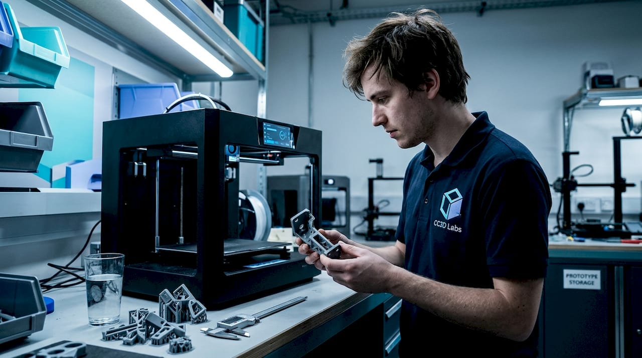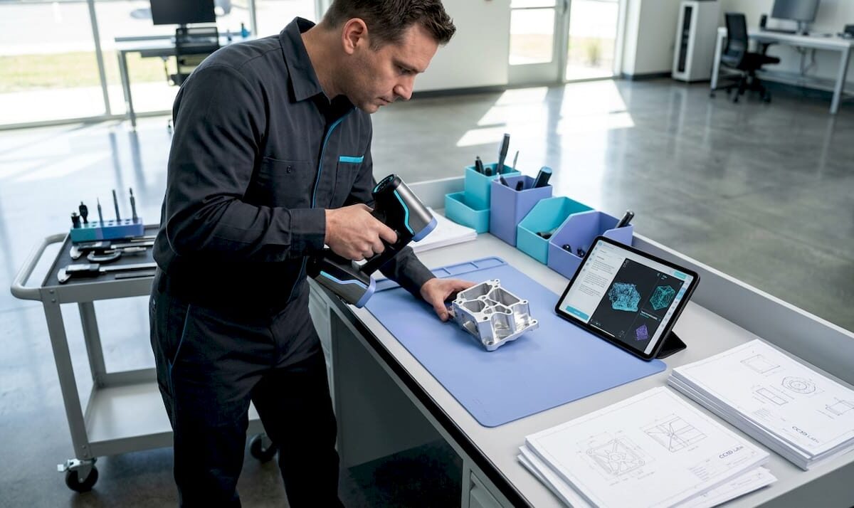
Technician calibrating 3D scanner in workshop

Archival 3D Scanning Guide for Product Development Precision


TL;DR:

  • Most engineers mistakenly assume that any 3D scan qualifies as archival, which can jeopardize long-term reuse. Achieving true archival 3D scanning requires detailed measurement records preserved in durable, open formats, alongside comprehensive documentation and calibration data. Proper workflow planning, including defining coordinate systems, controlling scan conditions, and maintaining metadata, is essential to ensure digital assets remain useful for decades.

Most engineers assume that any 3D scan is an archival scan. That assumption quietly kills product development programs. True archival 3D scanning means capturing high-fidelity 3D measurements of a physical object and preserving the resulting datasets, including raw scan data, derived models, and metadata, in durable, long-term formats designed for reuse years or even decades later. For product developers and manufacturers, that distinction is not academic. It determines whether your digital record can actually drive a reprint, a tolerance audit, or a design iteration in five years without starting from scratch.

Table of Contents

Key Takeaways

Point Details
Engineered for reuse Archival 3D scanning creates precise digital records that enable reliable prototyping and manufacturing, even decades later.
Workflow and validation matter Careful planning, calibration, and documentation make the difference between true archival utility and data loss.
No single file standard Long-term success relies on preserving both raw and interoperable files, plus metadata about methods and conditions.
Quality depends on application Material, surface, and intended use all impact how you capture and accept 3D scan data for the archive.

Archival 3D scanning: Definition and core concepts

With a shared understanding of why preservation matters, let’s clarify exactly what archival 3D scanning entails and why it differs from what most people picture.

An archival 3D scan is not simply a mesh you can rotate on screen. It is a structured measurement record built to survive software migrations, personnel changes, and years of engineering reuse. That distinction separates it from the ad-hoc scans common in hobbyist workflows or single-use inspection tasks, where the goal is a quick visualization, not long-term data fidelity.
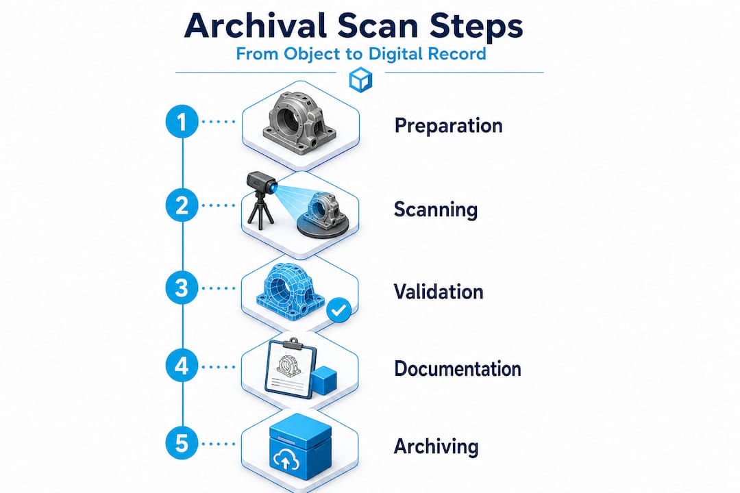
Vertical infographic showing archival 3D scan steps

Professional practice treats scans as measurement records that feed controlled workflows, including control networks, traceable deliverables, and field records, not just visualization models. This is precisely the standard that product engineers need to adopt.

The core concepts behind archival scanning include:

  • High-resolution capture: Point cloud density sufficient to resolve the finest functional features on your part
  • Traceable coordinate systems: Every dataset is registered to a defined spatial reference, so geometry is reproducible
  • Calibration documentation: The scanner’s measurement uncertainty is recorded, not assumed
  • Metadata preservation: Capture date, operator, equipment, ambient conditions, and processing parameters accompany every dataset
  • Controlled deliverable formats: Both raw scan files and processed derivatives are retained separately

“Archival quality is not a feature of the scanner. It is a property of the workflow, the documentation, and the intent behind the capture.”

Understanding design accuracy and prototyping requirements from the start lets your team define what “archival” actually means for your specific use case, whether that is heritage documentation, reverse engineering, or first-article inspection.

Critical workflow elements for archival 3D scanning

Understanding the goals of archival scanning, we next examine what it takes, in practice, for a scan to achieve those standards.

Engineer reviewing 3D scan accuracy checklist

The most common failure mode in archival scanning programs is treating the scan session itself as the entire workflow. In reality, the scan session is just the first step. What transforms raw point cloud data into a true archival resource is the controlled measurement package that surrounds it.

Your scanning checklist for accuracy should address five non-negotiable workflow elements:

  1. Coordinate system definition: Establish a fixed reference frame before scanning begins. Use physical control targets, monuments, or reference artifacts that can be reproduced in future sessions. Without a defined coordinate system, your scan is a floating geometry with no spatial anchor.
  2. Registration and control strategy: Document how individual scan positions were merged. Record the targets used, the registration algorithm, and the resulting residual errors. This documentation allows future engineers to verify alignment or re-register datasets from scratch if needed.
  3. Calibration and uncertainty documentation: Every scanner has a stated accuracy specification, but real-world accuracy depends on surface properties, distance, angle of incidence, and environmental conditions. Record the calibration certificate, the pre-capture validation routine, and any uncertainty estimates specific to the captured object.
  4. Raw file preservation: Never discard the original point cloud or structured scan data. Raw files are the ground truth. Processed meshes and derivative CAD models are interpretations. If your processing software introduces artifacts, the raw data is your only path to recovery.
  5. Metadata and provenance records: Log everything that a future engineer would need to understand the capture: scanner model, firmware version, resolution settings, ambient temperature, lighting conditions, and the name of the person who performed the scan.

Pro Tip: Create a standardized scan log template and require it to be completed before any scan session is closed out. Treat it like a lab notebook entry. Future engineers will thank you, and so will your quality management system.

The table below summarizes the key deliverables in a properly structured archival measurement package:

Deliverable Format Purpose
Raw point cloud Proprietary + open (e.g., .e57, .las) Ground truth reference
Registered scan assembly Project file + exported .e57 Reproducible spatial reference
Processed mesh .obj, .stl, or .ply Engineering and manufacturing use
Calibration record PDF or structured document Uncertainty traceability
Coordinate system definition Report or README file Spatial context for future users
Metadata log Structured text or database entry Provenance and repeatability

Following documentation strategies for workflows used in other precision industries reveals a pattern: the teams that document obsessively are the teams that can reproduce results years later without heroic reverse engineering efforts.

A high quality scan process also accounts for fixture design, lighting control, and surface preparation before the scanner is ever switched on. These upstream decisions directly determine whether your archived data is usable or merely stored.

For teams that want to access professional-grade equipment and validated workflows without building an in-house lab, partnering with a dedicated 3D scanning lab dramatically reduces the risk of workflow gaps.

Quality control: Materials, surfaces, and scan acceptance

With the core workflow defined, the next challenge lies in managing variable scan quality and ensuring reliable results across different object types.

Here is a fact that surprises many engineers early in their archival scanning programs: the scanner model matters far less than the strategy around it. Surface characteristics and acquisition conditions fundamentally change what is achievable in terms of accuracy, completeness, and dimensional fidelity. As a result, archival success depends on capture strategy, validation, and fit-for-purpose uncertainty, not only the scanner model.

The materials and surfaces that cause the most trouble in engineering environments include:

  • Highly polished or mirror-finish metals: Structured light and laser scanners struggle with specular reflections, producing noise or gaps in the point cloud
  • Transparent or translucent materials: Glass, clear polycarbonate, and acrylic are nearly invisible to most scanning technologies without surface treatment
  • Carbon fiber and dark matte composites: High light absorption causes inconsistent returns and reduced point density
  • Small radii and sharp internal corners: Occlusion and beam divergence limit coverage in tight geometries
  • Large flat surfaces: Can look easy but are prone to alignment drift during stitching if control targets are insufficient
Surface type Common challenge Recommended strategy
Polished metal Specular reflection, point cloud noise Apply matte scanning spray or use photogrammetry targets
Transparent plastic Scanner cannot detect surface Apply temporary matte coating, remove after scanning
Dark composite Low return signal, incomplete coverage Increase scan exposure or apply reference dots
Complex internal geometry Occlusion, coverage gaps Multi-angle capture with validated coverage maps
Large flat panels Alignment drift during stitching Dense target field with certified reference distances

Pro Tip: Define your acceptance criteria before you scan, not after. Set minimum point density thresholds, maximum allowable deviation from reference measurements, and coverage completeness requirements for each part type. This prevents the common situation where a scan session is declared “done” based on visual inspection of the mesh rather than verified measurement performance.

“A scan that looks complete on screen and a scan that is dimensionally complete are not the same thing. Only your acceptance criteria tell the difference.”

Achieving scan quality on engineering parts with challenging surfaces often requires a combination of technologies, structured light for geometry, photogrammetry for reference targets, and contact measurement for ground-truth validation on critical features. No single method covers every scenario, and the importance of 3D prototyping quality becomes apparent the moment a downstream manufacturing process depends on a scan that was never properly validated.

Archival file formats and long-term data preservation

Reliable scanning and quality control are just the start. To realize the enduring value of your scans, you must think strategically about file formats and data management.

One of the most common misconceptions is that choosing the right file format is a single decision made at the end of a scan session. In reality, format strategy needs to be baked into your workflow from day one.

Archival 3D preservation practices commonly emphasize retaining original, raw scan data and using open or interoperable formats for long-term access, while acknowledging there is no single universally agreed archival file format. That means your format strategy must be deliberately constructed rather than defaulted into.

Best practices for long-term data preservation include:

  • Retain raw master files: Keep the original capture files in the scanner’s native format alongside exported open formats. Native formats contain the most complete data, while open formats ensure future accessibility.
  • Use a dual-track approach: Maintain one copy in the most complete format available (often proprietary) and a second copy in a widely readable open format such as .e57 for point clouds or .obj and .ply for meshes.
  • Store metadata separately and explicitly: Do not rely on metadata embedded in the file header alone. Write a separate README or structured document that captures every piece of provenance information.
  • Version your derivative models: When you process a raw scan into a mesh or CAD model, keep a record of what processing steps were applied and what software version was used.
  • Plan for format migration: No format is permanent. Schedule periodic reviews of your archive to assess whether stored formats remain accessible with current software, and migrate to updated formats before the old ones become unreadable.
Format Type Strengths Limitations
.e57 Point cloud (open) Widely supported, stores metadata No mesh representation
.las / .laz Point cloud (open) Common in survey workflows Limited metadata fields
.ply Mesh (open) Stores color and normals Less common in CAD workflows
.obj Mesh (open) Universal readability No intrinsic coordinate metadata
.stl Mesh (open) Universal for manufacturing No color, limited precision
Native formats (.zprj, .fls, etc.) Proprietary Maximum data fidelity Software-dependent, risk of obsolescence

Understanding the full landscape of top CAD file formats helps teams make informed decisions about which derivatives to produce and which formats will survive software upgrades over a ten-year horizon.

The uncomfortable truth: Why archival 3D scanning rarely succeeds without planning

Armed with best practices, let’s take a candid look at the rarely discussed pitfalls and what separates archival success from irretrievable data loss.

Most archival 3D scanning programs fail quietly. They do not fail dramatically with error messages or system crashes. They fail years later when an engineer opens a scan archive and finds that the metadata is missing, the coordinate system was never documented, the software that created the native files is no longer available, and the raw data was overwritten to save storage space. At that point, the “archive” is just a collection of orphaned meshes.

The root cause is almost always the same: teams treated archival scanning as a data collection task rather than an engineering discipline. Scanning is the physical act. Archival scanning is the system of decisions, documentation, and maintenance that makes those scans permanently useful.

Because there is no single universal archival 3D file format, engineers need to implement a dual track strategy, retaining raw and master files alongside interoperable derivatives, and preserving metadata and provenance so future teams can reconstruct the intended geometry and processing parameters without guesswork.

The mindset shift required here is significant. Stop thinking of your scan archive as a file folder and start thinking of it as a controlled measurement library. Every entry in that library should be retrievable, understandable, and reproducible by someone who was not in the room when the scan was captured.

What we have seen consistently at CC 3D Labs is that teams who invest in upfront planning, defining their acceptance criteria, establishing their coordinate systems, and committing to their dual-track format strategy before the first scan session, build archives that actually get used. Teams that treat these steps as optional administrative overhead end up rebuilding scans from scratch at exactly the wrong moment, typically when a key product is facing a design change or a regulatory audit.

A commitment to innovation in product development means treating your digital records with the same rigor you apply to your physical parts. Your scan archive is a manufacturing asset. Protect it accordingly.

Next steps: Partnering for archival 3D scanning and prototyping success

For product developers who are ready to move from theory to practice, the fastest path to a functional archival scanning program is partnering with a lab that already understands the nuances of measurement-grade capture and long-term data management.

https://cc3dlabs.com

CC 3D Labs provides professional handheld 3D scanning services (accuracy to ~0.1 mm) near Philadelphia, serving product developers and engineering teams who need scans that are genuinely fit for manufacturing, not just for viewing. Our workflows address coordinate system setup, calibration documentation, multi-format deliverables, and provenance records as standard practice, not add-ons. Whether you are reverse engineering a legacy component, creating a first-article inspection baseline, or building a long-term digital archive for a product line, we can structure a scanning program that meets your specific engineering requirements. Explore our scanning for accuracy and prototyping capabilities, or browse the full range of our 3D printing services to see how scanning and fabrication work together in a single, integrated workflow.

Frequently asked questions

What makes a 3D scan “archival” compared to a regular scan?

An archival 3D scan is a high-fidelity measurement record preserved with metadata, calibration documentation, and traceable coordinate systems in open formats designed for reliable reuse over years or decades, rather than a one-time visualization output.

Is there a universal file format for archival 3D scans?

No single standard exists. Best practice is to maintain raw master files alongside interoperable open-format derivatives such as .e57 for point clouds and .ply or .obj for meshes, ensuring future accessibility regardless of software changes.

What factors most affect the accuracy of an archival 3D scan?

Surface properties, lighting conditions, and scanner angle all influence results, but archival success ultimately depends on the capture strategy, validation protocol, and fit-for-purpose acceptance criteria applied to each specific object and application.

How can I ensure that my 3D scan data will still be usable in ten years?

Store original raw data and processed derivatives in open or widely supported formats, pair them with explicit metadata documentation, and schedule periodic format migration reviews to prevent format obsolescence before it becomes a problem.
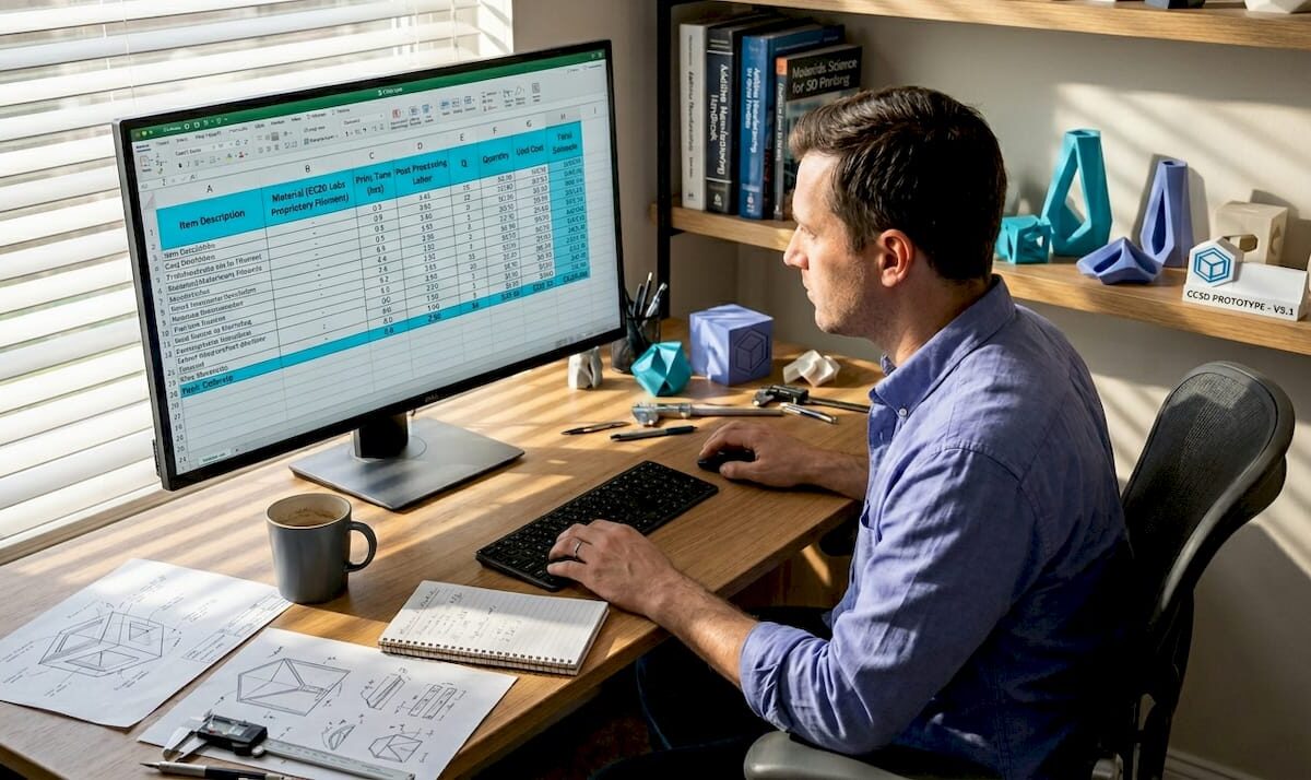
Product developer analyzing 3D printing costs

Cut 3D Printing Costs: Proven Strategies for Product Developers


TL;DR:

  • Managing 3D printing expenses involves considering labor, machine time, design complexity, and overhead, which often outweigh raw material costs.
  • Optimizing design and workflow, choosing suitable materials, and evaluating alternative manufacturing methods are crucial steps to ensure cost-effective production.

Managing 3D printing expenses is rarely as simple as buying cheaper filament or running machines faster. The real cost picture includes labor, machine time, design complexity, post-processing, and purchase overhead, and businesses that focus only on one variable often end up paying more overall. Whether you’re producing custom prototypes or scaling toward batch manufacturing, understanding how costs actually stack up, and where to apply targeted reductions, can dramatically change your bottom line. This article lays out research-backed methods to help product developers and manufacturing businesses reduce 3D printing expenses without compromising part quality.

Table of Contents

Key Takeaways

Point Details
Major cost drivers Material, labor, and purchase costs are the biggest factors in 3D printing expenses.
Design optimization impact Smart design choices can cut up to 54% of print time and 16% of material use.
Workflow efficiencies matter Batching and efficient post-processing help lower per-part costs significantly.
Material and process fit Matching the right material and printing process to your project prevents overspending.
Alternative solutions Sometimes, traditional manufacturing is cheaper—make cost-based decisions, not just tech-based ones.

Understand the real cost drivers in 3D printing

Most businesses assume material is the biggest cost in 3D printing. That assumption is frequently wrong, and it leads to poor decisions. A thorough cost breakdown reveals that labor, machine time, design complexity, and purchase overhead often outweigh raw material expense, particularly in custom or low-volume scenarios.

Here’s a breakdown of the main cost factors you need to track:

  • Material cost: Filament, resin, or powder consumed during printing, including support material that gets discarded
  • Machine time: The hours a printer runs to complete a job, which directly ties to energy consumption and capacity allocation
  • Labor: Time spent on setup, monitoring, support removal, finishing, and quality checks
  • Purchase cost: Amortized cost of equipment, software licenses, and facility overhead
  • Design complexity: More complex geometries require longer print times, more support, and more labor to finish

A clinical study evaluating 3D-printed orthoses against traditionally manufactured ones found that labor and purchase cost dominated the 3D printing expense structure. Labor alone accounted for 62.2% of total cost, while purchase cost contributed 22.2%. By comparison, conventional thermoplastic orthoses relied mainly on material (69.4%) and labor (30.6%).

Cost factor 3D-printed orthosis Conventional orthosis
Labor 62.2% 30.6%
Purchase cost 22.2% N/A (minimal overhead)
Material Smaller share 69.4%
Mean total cost €46.54 €30.28

In some product categories, 3D printing is not automatically cheaper. Labor and overhead can push total cost well above what conventional manufacturing would charge. Accurate cost analysis always has to account for all six factors, not just material weight.

For your planning, you can get accurate 3D printing cost estimations upfront before committing to a production run. Knowing your full cost structure is the first step toward finding where to cut.

Optimize your design for cost-effective printing

Knowing what affects your costs, the next step is learning how your design decisions directly alter material, labor, and time expenses. Design is where the biggest leverage lives, and most businesses underuse it.

Engineer optimizing 3D printing design

Multi-objective optimization means adjusting your model to minimize two or more cost factors at the same time, rather than just solving for one. For example, reducing overhangs reduces support material, but doing that alone may increase print height and extend print time. A multi-objective approach balances both simultaneously.

Published research shows that multi-objective design optimization reduced material use by 11 to 16% and print time by 12 to 54% compared to sequential single-variable optimization. That kind of improvement does not require a major redesign. It requires the right design review process.

Practical design changes that reduce cost:

  • Reduce part height: Taller prints take longer, layer by layer. Reorienting a part, when the geometry allows, can dramatically cut print time.
  • Minimize overhang angles: Overhangs beyond 45 degrees typically require support. Each gram of support material adds both material cost and removal labor.
  • Hollow non-structural sections: Infill is one of the most adjustable cost levers. Reducing infill density where strength is not critical directly cuts material and time.
  • Simplify surface features: Fine decorative details increase print time without adding structural value for functional parts.
  • Split and reassemble complex geometries: Sometimes printing a part in two simpler pieces, then joining them, is cheaper than printing a complex monolithic form.

Pro Tip: Before sending any file to print, run a quick design checklist that flags overhangs, wall thickness violations, and unnecessary height. Many of the biggest cost savings happen at this stage, before a single layer is laid down. For a deeper look at designing reliable prints, CC 3D Labs has practical guidance specific to functional prototypes and production parts.

The right material choice also matters here. Some designs that look complex in one material become simpler and cheaper in another. Explore choosing cost-efficient materials to understand how material selection interacts with your design geometry.

Choose the right materials and process for your application

While design is crucial, your choice of material and print process can make or break your savings. Let’s compare how different options shift the cost equation depending on whether you’re making prototypes or end-use parts.

The core principle here is that the cheapest prototyping process is rarely the cheapest production process. PLA is inexpensive and prints quickly, making it ideal for concept models. But for functional end-use parts, it may fail under load or temperature, leading to reprints and wasted cost. Choosing a stronger material upfront, even if it costs a bit more per kilogram, can reduce total cost over a product’s lifecycle.

As research confirms, objective importance varies by AM method, meaning that what you optimize for, whether material, time, or support volume, should change depending on which print technology you’re using. FDM, SLA, and SLS all have different dominant cost drivers.

Here’s a practical comparison:

Technology Typical material Best use case Primary cost driver
FDM (filament) PLA, PETG, ABS, ASA Prototypes, functional parts, jigs Machine time, labor
SLA (resin) Photopolymer resin High-detail prototypes, patterns Material cost, post-processing
SLS (powder) Nylon, TPU Complex geometry, batch production Machine and powder cost
Metal AM Stainless, titanium Aerospace, medical, high-stress parts Material and machine cost

How to evaluate your material and process combination step by step:

  1. Define the functional requirement: What stress, temperature, and environment will this part face?
  2. Identify the minimum viable material: Choose the least expensive material that meets that requirement, not the most capable one.
  3. Calculate total cost, not just material cost: Include setup, print time, post-processing, and failure rate.
  4. Compare against alternatives: A simple injection-molded or machined part may cost less at volume, even if 3D printing is cheaper per prototype.
  5. Check batch economics: Some processes become cost-competitive only above certain volumes. SLS, for example, benefits significantly from packing multiple parts into a single build.

For businesses scaling from prototyping toward higher volumes, reviewing a production-grade printing guide will clarify when to switch processes and how to manage the transition economically. If you’re still evaluating what project type fits your production needs, matching print jobs to needs can help you narrow it down faster.

Streamline your workflow to reduce hidden costs

After selecting your ideal material and process, it’s time to address workflow tweaks that further slash hidden or secondary costs. These are the expenses businesses rarely track, yet they compound quickly.

Labor, as the data shows, is the largest cost factor in many 3D printing scenarios, making up 62.2% of total cost in real production environments. That means any workflow step that consumes labor, without adding direct value to the finished part, is a cost reduction opportunity.

Key workflow strategies to implement:

  • Batch similar parts together: Combining multiple small jobs into a single build plate reduces setup time and maximizes machine utilization. Each setup avoided is labor saved.
  • Standardize post-processing steps: When post-processing follows a consistent sequence, workers complete it faster and make fewer errors. Random or ad hoc finishing inflates labor time.
  • Track failure rates by design and material: If certain part configurations fail print quality checks regularly, the rework cost is invisible but real. Logging failures helps you identify and fix root causes.
  • Reduce unnecessary support structures at the workflow level: Even after design optimization, slicing software settings can further minimize support. Spending a few extra minutes in the slicer often saves more time in post-processing.
  • Consolidate orders: Sending multiple small orders separately is almost always more expensive per part than consolidating them into planned batch runs.

Pro Tip: Use digital job tracking tools, even a simple shared spreadsheet, to log setup times, failure rates, and post-processing hours per job type. Within a few weeks, patterns emerge that reveal where your actual time and money are going. For specific low-volume manufacturing tips tailored to 3D printing, CC 3D Labs offers practical guidance from real production experience.

Staying current on process innovation also matters. Reviewing latest cost-saving trends in 3D printing manufacturing for 2026 can reveal new materials, software tools, or workflow approaches that further cut costs without requiring major investment.

Know when 3D printing isn’t the cheapest solution

Even the best cost-cutting strategies have limits. Sometimes, the wisest move is to opt out of 3D printing entirely for a given part. Recognizing this scenario early prevents you from sinking optimization effort into a process that was never the right fit.

The orthosis research is a clear example. Even after accounting for reduced material waste in 3D printing, the mean cost per 3D-printed part was €46.54 versus €30.28 for the conventionally manufactured version. The labor and purchase overhead of 3D printing erased any material savings.

Warning signs that 3D printing may not be your cheapest option:

  • High labor for finishing: If your parts require extensive sanding, painting, assembly, or inspection after printing, labor costs escalate fast
  • Large production volumes: At high quantities, injection molding or die casting often delivers a lower per-part cost
  • Simple, flat, or extrudable geometry: Parts that can be cut, stamped, or machined from stock material are usually cheaper to produce conventionally
  • Tight dimensional tolerances: When post-machining is required to hit tolerance, the combined cost of printing plus machining often exceeds just machining from the start
  • Heavy parts: Dense, heavy parts require significant material and print time, reducing the cost advantage of 3D printing versus alternatives

Always compare your 3D printing cost estimate with at least one alternative manufacturing method before committing. Sometimes conventional or hybrid manufacturing delivers greater savings, especially when labor and post-processing are factored in correctly.

Understanding your 3D printing alternatives is not a concession to failure. It’s smart cost strategy. The goal is always the right process for the job, not loyalty to any single technology.

Our take: Cost cutting isn’t about one magic fix

After walking through all of these methods, here’s the perspective that often gets left out of cost reduction conversations. Businesses frequently chase the single biggest lever, whether that’s cheaper filament, a faster printer, or a new slicer setting, expecting it to solve their cost problem. It rarely does.

Real cost reduction in 3D printing is additive. It comes from stacking several small wins: a better-designed part, an appropriate material, batched workflow, and honest process selection. Each individual change may save 5 to 15% in isolation. But combined, they often cut total production cost by 30 to 50% without sacrificing part quality.

The uncomfortable truth is that the most expensive mistake is not choosing the wrong material. It’s running an unoptimized process repeatedly and measuring only the material cost. Labor is the hidden giant in most manufacturing environments, and 3D printing is no exception.

We’ve also seen businesses resist switching away from 3D printing for a specific part because they’ve invested in the workflow. That’s a sunk cost bias. When a conventional process is genuinely cheaper, making the switch is not a setback. It’s what good cost management looks like.

Tracking manufacturing trends insight helps you stay current as the economics of different technologies shift year over year. The right answer today may look different in 18 months as new materials and processes enter the market.

The most effective cost strategy we see at CC 3D Labs is a simple one: analyze all cost drivers, optimize design first, choose the minimum viable material and process, batch the workflow, and then honestly evaluate whether 3D printing is the right call for each job. That sequence, applied consistently, delivers better savings than any single optimization ever could.

Take the next step with expert 3D printing support

Implementing these strategies on your own takes time, and miscalculations can cost more than the savings you’re chasing. Working with a specialist who understands the full cost picture from design through finishing makes the entire process faster and more predictable.

https://cc3dlabs.com

CC 3D Labs works with product developers and manufacturing businesses across the Philadelphia region and beyond, helping them reduce costs through smarter design, material selection, and production planning. Our professional 3D printing services cover everything from early-stage prototyping to batch production runs, with transparent pricing and fast turnaround. If you’re not sure where to start, explore 3D printing options to see what’s possible, then reach out for a free estimate tailored to your specific project and volume.

Frequently asked questions

What is the most effective way to cut 3D printing costs?

Optimizing your design with a multi-objective approach is one of the highest-impact changes you can make, with material and time savings of up to 16% and 54% respectively. Layering that with workflow batching and honest process selection multiplies the impact further.

Are labor and purchase costs more important than materials in 3D printing?

In many real-world production scenarios, yes. Studies show labor accounts for 62.2% of total 3D printing cost, making it the dominant expense, not material.

When is 3D printing not the cheapest solution?

When parts require heavy finishing, have simple geometry, or are produced in high volumes, conventional manufacturing often wins on cost. Research confirms 3D printing can cost more than alternatives even when material waste is reduced, once labor and overhead are counted.

Does batch size affect 3D printing costs?

Yes. Larger batches reduce the per-part burden of setup, machine initialization, and labor, making the unit cost fall significantly as batch size increases.

Can support volume and overhang area impact cost?

Absolutely. Support structures add material cost and, more importantly, removal labor. Design changes that eliminate or minimize support, as shown by multi-objective optimization research, directly reduce both cost categories at once.

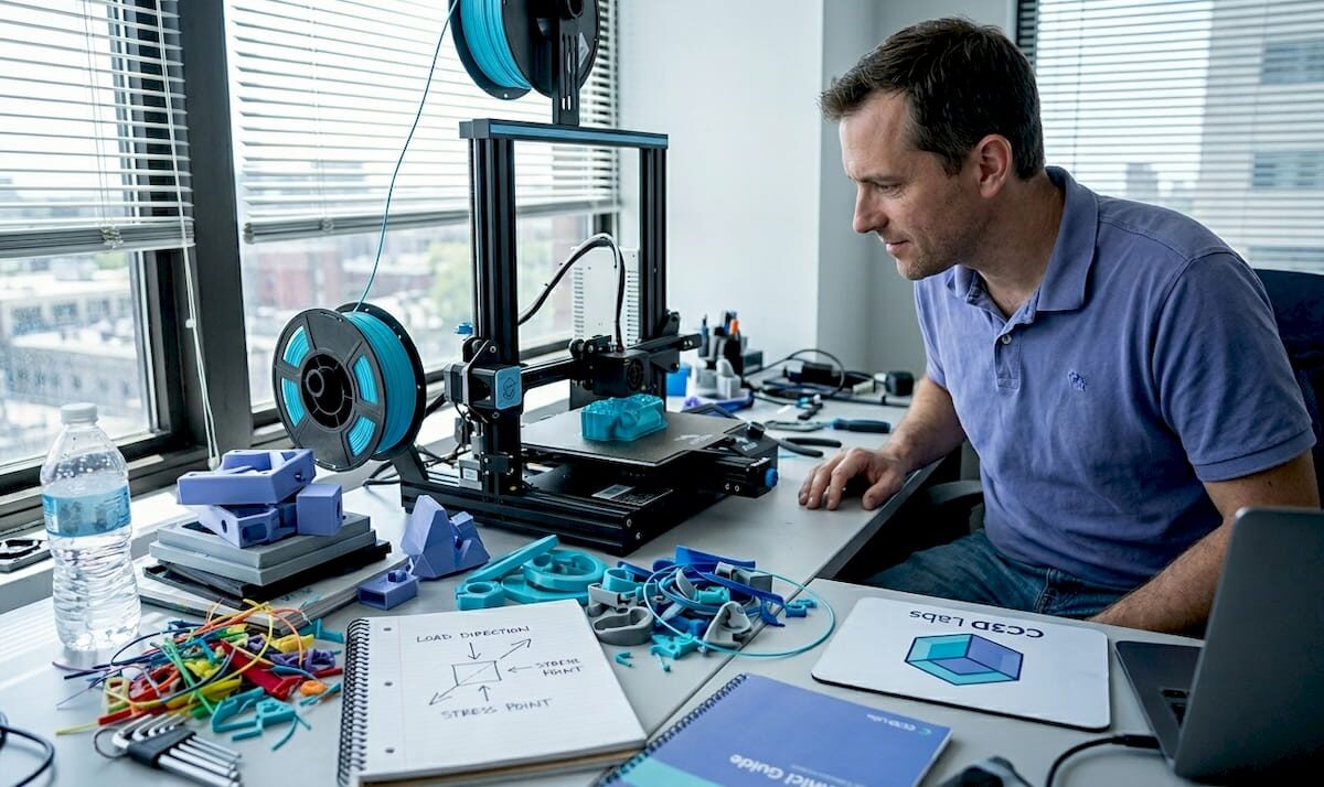
Product developer monitoring desktop 3D printer

Overcome common 3D printing challenges: pro tips for product developers


TL;DR:

  • Many common FDM print failures, such as warping, poor bed adhesion, and anisotropy, arise from thermal and structural issues. Addressing enclosure temperature, bed surface prep, and layer orientation can significantly improve mechanical strength and dimensional stability. Mastering systematic failure analysis with optimized parameters and environment controls distinguishes top engineers from novices.

You pull a prototype off the build plate, measure it against spec, and it’s warped 2mm at the corner. The layer interface cracked under a basic load test. Your material cost is sunk, your timeline is slipping, and the root cause isn’t obvious at first glance. These aren’t rare flukes — they’re predictable failure modes with known solutions. This article walks you through the most persistent mechanical, material, and dimensional challenges in FDM 3D printing, with data-backed strategies and practical settings adjustments you can act on today.

Table of Contents

Key Takeaways

Point Details
Tackle warping and adhesion Control thermal gradients and use enclosures to promote strong first layer and prevent warping.
Optimize infill for strength Select infill and layer parameters based on material and mechanical performance targets.
Minimize dimensional drift Account for thermal cycling and orientation to maintain tight tolerances.
Embrace expert tuning Advanced troubleshooting and layering techniques resolve stubborn quality issues for production parts.
Professional help speeds results When issues persist, specialist 3D printing services can accelerate troubleshooting and delivery.

Mechanical issues: warping, bed adhesion, and anisotropy

Most print failures trace back to three interconnected problems: warping, poor bed adhesion, and structural weakness from anisotropy. Understanding why each happens is the first step toward eliminating them from your workflow.

Warping and poor bed adhesion are among the most common mechanical challenges in FDM printing, caused by thermal shrinkage and uneven cooling, particularly with ABS and Nylon. When the bottom layers cool faster than the layers above them, differential contraction bends corners upward. This is especially destructive for flat, wide parts where the geometry amplifies every degree of temperature change.

For engineers building functional prototypes, the fix involves more than just spreading glue stick on the print bed. Here are the main factors to address:

  • Enclosure temperature control: Keep ambient air around 40 to 50°C for ABS; this slows the cooling rate and reduces stress buildup between layers.
  • Bed surface and prep: Use PEI sheets, glass with adhesive, or specialized surfaces matched to your material. Clean with IPA before every run.
  • First layer calibration: A first layer squished 10 to 15% below nominal layer height maximizes contact area and adhesion force.
  • Brim and raft usage: Wide brims (at least 8mm) physically resist corner lift. Rafts add thermal mass at the base and help equalize temperature.

“For materials prone to warping like ABS and Nylon, enclosing the build volume and tightly calibrating the first layer settings are non-negotiable steps before advanced parameter tuning.” — Recommendations from FDM troubleshooting best practices.

Anisotropy is the other silent killer. Because FDM prints layer by layer, the bond between layers is always the weakest link in the structure. Flexural strength drops 40%+ at a 90° raster angle compared to 0°, with PLA reaching optimal performance at 0° orientation and 50% infill (167 MPa flexural in one published study — typical PLA flexural values run 80–110 MPa), and ABS peaking at 0° orientation with 75% infill (126 MPa). If your part will see bending loads, the layer stacking direction relative to load direction is not a detail — it’s a design decision.

When working on manufacturing-grade 3D printing projects, these baseline mechanical principles need to be locked in before you start optimizing higher-level parameters.

Pro Tip: Before printing any structural prototype, sketch out the primary load direction on paper and orient the model so critical surfaces are parallel to the raster lines. This one decision can roughly double effective flexural strength without changing a single slicer setting.

For anyone newer to these concepts, the filament 3D printing prototyping guide provides a solid foundation before tackling advanced troubleshooting.

Strength and material parameter selection: the infill and raster effect

Once you understand the mechanical failure sources, the next problem is knowing exactly which parameters to adjust for your specific material and application. Infill and raster angle are not just cosmetic settings — they are structural design variables.

Infill density contributes up to 80% of the variation in tensile, compressive, and impact strength, while layer thickness has the biggest influence on hardness and surface roughness. The practical implication: if you need a load-bearing part, infill is your primary lever. If you need a smooth surface for a fit-check prototype, layer thickness takes priority.

Here’s a step-by-step approach to selecting infill and raster angle for common engineering materials:

  1. Identify the primary load type (tensile, compressive, bending, impact). Each responds differently to infill patterns and density.
  2. Select material based on operating environment. ABS for moderate heat and chemical exposure, PLA for room-temperature prototypes, Nylon for dynamic or fatigue-heavy applications.
  3. Set raster angle to 0° as the starting default for maximum strength in the load direction. Reserve 45° or alternating rasters for isotropic requirements.
  4. Set infill starting point based on the table below, then adjust after a destructive test sample.
  5. Print a small coupon first. Test before committing material and time to the full part.
Material Optimal raster angle Infill % Flexural strength Notes
PLA 0° 50% 167 MPa (study value) Best for room-temp structural prototypes
ABS 0° 75% 126 MPa (study value) Needs enclosure; warping risk above 100mm
Nylon 0° to 45° 60 to 75% Varies Moisture absorption affects results; dry filament before printing
PETG 45° alternating 50 to 60% ~120 MPa Good layer adhesion; less anisotropy than ABS

The optimal mechanical parameters for each material matter, but they only deliver results when the print environment (enclosure, bed temp, ambient humidity) supports them. Engineers who treat slicer settings as isolated variables without controlling the full print environment consistently get inconsistent results.

Pro Tip: Run a 3-sample destructive test at your target infill and raster settings before committing to a full production run. A simple bend or pull test on small coupons catches 80% of strength-related surprises before they cost you time and material on full-sized parts.

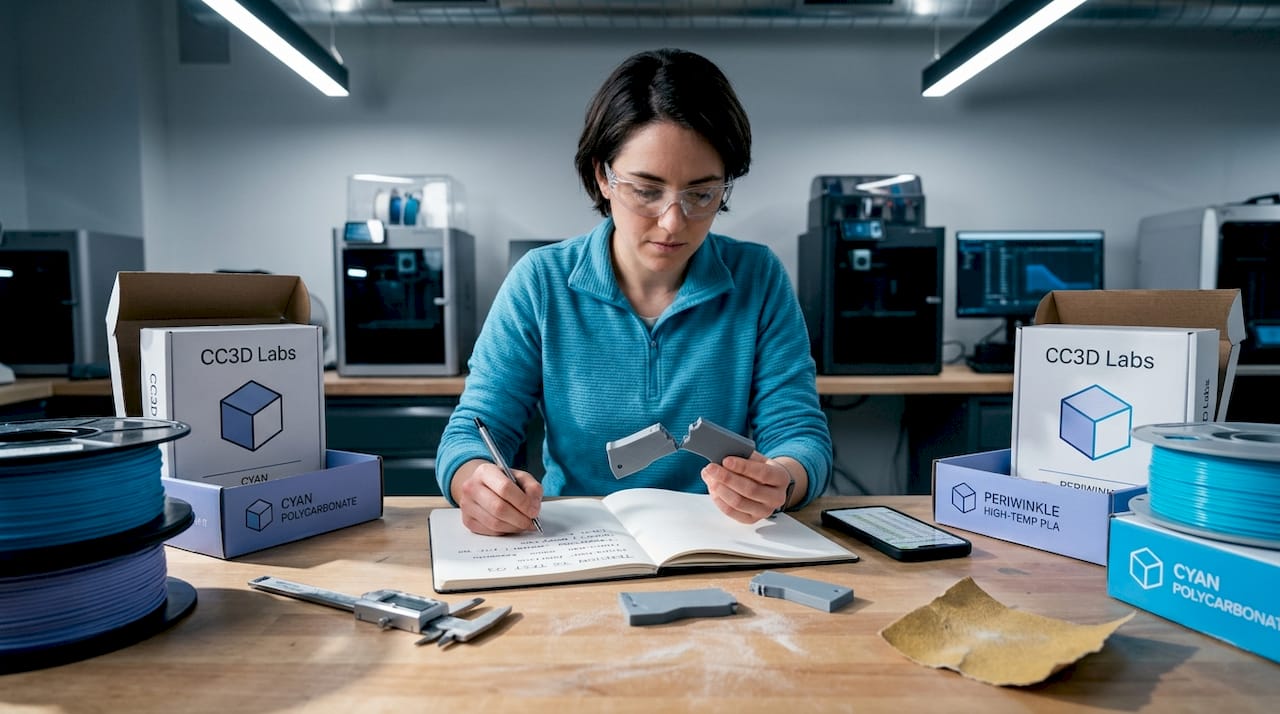
Engineer examines broken 3D printed samples

For a deeper look at how geometry choices interact with these parameters, the resource on designing reliable 3D prints is worth reviewing before finalizing your CAD for print.

Dimensional accuracy and stability under thermal cycling

Strength and adhesion matter at print time, but many engineering parts face an equally serious challenge after they leave the printer: dimensional instability under repeated temperature changes. This is critical for any part used in automotive testing, outdoor hardware, or environments with significant temperature swings.

Dimensional drift under thermal cycling is well-documented: parts can show a height increase of +0.3 mm after just 10 cycles between -20°C and 80°C, with the Z-direction the most affected due to anisotropy between layers. For parts with tight tolerances on height, stacking, or assembly clearance, that 0.3 mm can mean the difference between a fit and a failure.

The Z-direction is vulnerable for a structural reason: the bond between layers is weaker than the base polymer itself. When thermal expansion and contraction work on that interface repeatedly, the cumulative dimensional shift is greater than what you’d see in an injection-molded part made from the same base material.

Here’s a practical checklist to minimize thermal drift in dimensionally critical parts:

  • Pre-condition parts before measuring. Let them stabilize at room temperature for at least 2 hours after printing before taking dimensional readings.
  • Orient tall features horizontally where tolerance matters. A feature that runs in the XY plane is more dimensionally stable than one that grows in Z.
  • Use an enclosure during printing to slow cooling uniformity and reduce residual stress that contributes to post-print drift.
  • Anneal parts after printing. For PLA, annealing at 80 to 100°C for 30 to 60 minutes (above PLA’s ~60°C glass transition — below that, annealing does little) stress-relieves the polymer and improves dimensional stability under subsequent thermal loads.
  • Specify material with appropriate thermal coefficient. PETG and ABS both outperform PLA at elevated temperatures; check the glass transition temperature against your expected operating range.

If you’re not familiar with terms like anisotropy, glass transition temperature, or layer adhesion mechanics, the 3D printing terminology resource breaks these down clearly for product developers.

The industry is also moving toward tighter process controls for thermal stability, which you can explore in manufacturing trends in 3D printing to understand where the best practices are headed in 2026.

Expert troubleshooting: fine-tuning, layering, and advanced material tips

With the fundamentals addressed, the final layer of mastery involves diagnosing persistent quality issues that survive basic parameter optimization. These are the problems that show up in advanced prototypes and pre-production runs, and they require a more systematic approach.

The following troubleshooting moves address common high-level flaws:

  • Stringing and oozing: Increase retraction distance by 0.5mm increments and reduce travel speed. Dry filament thoroughly before printing, especially with hygroscopic materials like Nylon and PETG.
  • Under-extrusion: Check for partial clogs, recalibrate the extruder e-steps, and verify that flow rate matches actual filament diameter at the tip.
  • Layer separation: Increase layer temperature in 5°C increments and reduce print speed on perimeter passes. Check that part cooling fans aren’t overwhelming inter-layer bonding on materials like ABS.
  • Surface inconsistency on top layers: Increase top layer count from 3 to 5, and verify that infill percentage is high enough to support bridging at the top.

Retraction and flow calibration directly affect part quality in ways that don’t show up in standard strength testing but can catastrophically affect functional performance and appearance. Setting 0° raster and 50 to 75% infill for maximum structural performance is part of this optimization loop.

Advanced layering strategies deserve particular attention for fatigue applications. Multiplane layering, where the model is split and printed in sections oriented on different axes, can meaningfully mitigate Z-direction weakness. It adds complexity, but for parts that will see cyclic loading, it’s a legitimate engineering intervention rather than a workaround.

“Notches and stress concentrations in printed parts reduce fatigue life dramatically. A sharp root radius of just 0.3 mm can reduce epoxy fatigue life by two-thirds, and the same principle applies to layer transitions and internal geometry in FDM parts.”

This is an often-overlooked design point. Engineers frequently focus on infill percentage and raster angle while ignoring sharp internal corners or abrupt geometry transitions that act as stress concentrators during cyclic loading. Rounding internal radii to at least 0.5mm and smoothing layer transition geometry can have more impact than an extra 10% of infill.

For a full walkthrough of how to implement these strategies from print setup through post-processing, the step-by-step guide for quality prints provides actionable detail on each stage.

Comparison summary: challenges, impacts, and solutions at a glance

Use this table as a reference checklist when diagnosing a failed print or planning a new high-stakes prototype.

Challenge Symptom Root cause Affected property Proven fix
Warping Lifted corners, base distortion Uneven cooling, thermal shrinkage Dimensional accuracy, adhesion Enclosure, heated bed, brim, first layer calibration
Anisotropy Weak Z-axis fractures Layer bonding weaker than bulk Flexural and tensile strength 0° raster, orientation control, multiplane layering
Poor bed adhesion Part detaches mid-print Dirty bed, wrong surface, low temp Print completion, dimensional base IPA clean, PEI sheet, bed temp match to material
Dimensional drift Tolerance failure after use Thermal cycling, Z-anisotropy Assembly fit, tolerance stack-up Pre-conditioning, annealing, horizontal feature orientation
Strength loss Fracture under expected load Low infill, wrong raster, wrong material Load-bearing capacity Optimize infill, raster angle, run coupon tests

Each row in this table maps to a root cause you can test and a fix you can implement immediately. The most common mistake is treating these as unrelated problems when they often compound: warping creates residual stress that worsens anisotropy-driven failure under load.

Beyond the basics: why mastering failure modes separates top engineers

Here’s an uncomfortable observation from working with product developers at all levels: the engineers who produce the most reliable printed parts aren’t necessarily using better machines or more exotic materials. They’re the ones who document failures systematically and treat every failed print as diagnostic data.

Textbooks cover the ideal behavior of materials. They rarely cover what happens when ABS prints on a Tuesday in summer at 72% humidity and the first layer adhesion degrades compared to a dry February run. The real world is messy, and default slicer profiles are designed for average conditions, not for your specific geometry, ambient environment, or load requirements.

The engineers who outperform their peers share a common habit: they don’t accept “it just failed” as a root cause. They ask which direction it failed, at what layer, under what load, after how many cycles. That diagnostic precision is what allows rapid iteration instead of repeated guessing.

Chasing new printer releases or exotic filaments without mastering failure analysis is a trap. A well-dialed FDM printer with calibrated settings for manufacturing-grade print quality will consistently outperform a newer machine running on default profiles. Process mastery compounds. Hardware upgrades plateau.

The engineers who build durable, accurate prototypes are the ones who embrace the analytical layer underneath the print settings. That’s not a personality type. It’s a skill you build deliberately, starting with the frameworks in this article.

Professional support and rapid solutions for 3D printing challenges

Persistent print failures can eat weeks of development time when you’re working without access to experienced process feedback. Sometimes the fastest path forward isn’t tuning another setting — it’s getting a professional set of eyes on your geometry, material selection, and print strategy.

https://cc3dlabs.com

At CC 3D Labs, we work directly with product developers and engineers facing exactly the challenges covered in this article. Whether you need rapid turnaround on a tight-tolerance prototype, expert guidance on material and parameter selection, or reliable batch production with verified dimensional accuracy, our team near Philadelphia is set up to deliver. Explore our full 3D printing services, or start with the guide to rapid prototyping to understand how a professional workflow compresses your iteration cycle. For filament-based projects specifically, prototyping with filament printing outlines exactly how we approach each stage from design review to final part delivery.

Frequently asked questions

What causes prints to warp during 3D printing?

Warping is caused by uneven cooling and thermal shrinkage in the base layers, especially with ABS and Nylon. Using an enclosure, a heated bed, and a wide brim effectively reduces warping across most material types.

How does infill density affect part strength in 3D printing?

Infill density contributes up to 80% of the variation in tensile, compressive, and impact strength in FDM printed parts. Higher infill significantly increases load-bearing capacity while layer thickness primarily affects surface hardness and finish.

Why are parts weaker in the Z-direction in FDM 3D printing?

The 40%+ drop in flexural strength at 90° raster angle compared to 0° is a direct result of inter-layer bonding being weaker than the bulk polymer. Orienting the part so critical load paths run in the XY plane is the most effective structural mitigation.

What is the impact of thermal cycling on dimensional accuracy?

Thermal cycling induces measurable dimensional drift, with parts showing up to +0.3 mm height change after 10 cycles between -20°C and 80°C. The Z-direction is most vulnerable due to the anisotropic nature of layer bonding in FDM parts.

How can I improve bed adhesion for better 3D print results?

Clean the print bed with IPA before each run, use a surface matched to your material like PEI for ABS or glass for PLA, and calibrate your first layer height to slightly over-extrude for maximum contact area. Adding an enclosure to stabilize ambient temperature eliminates the thermal differential that causes early delamination.

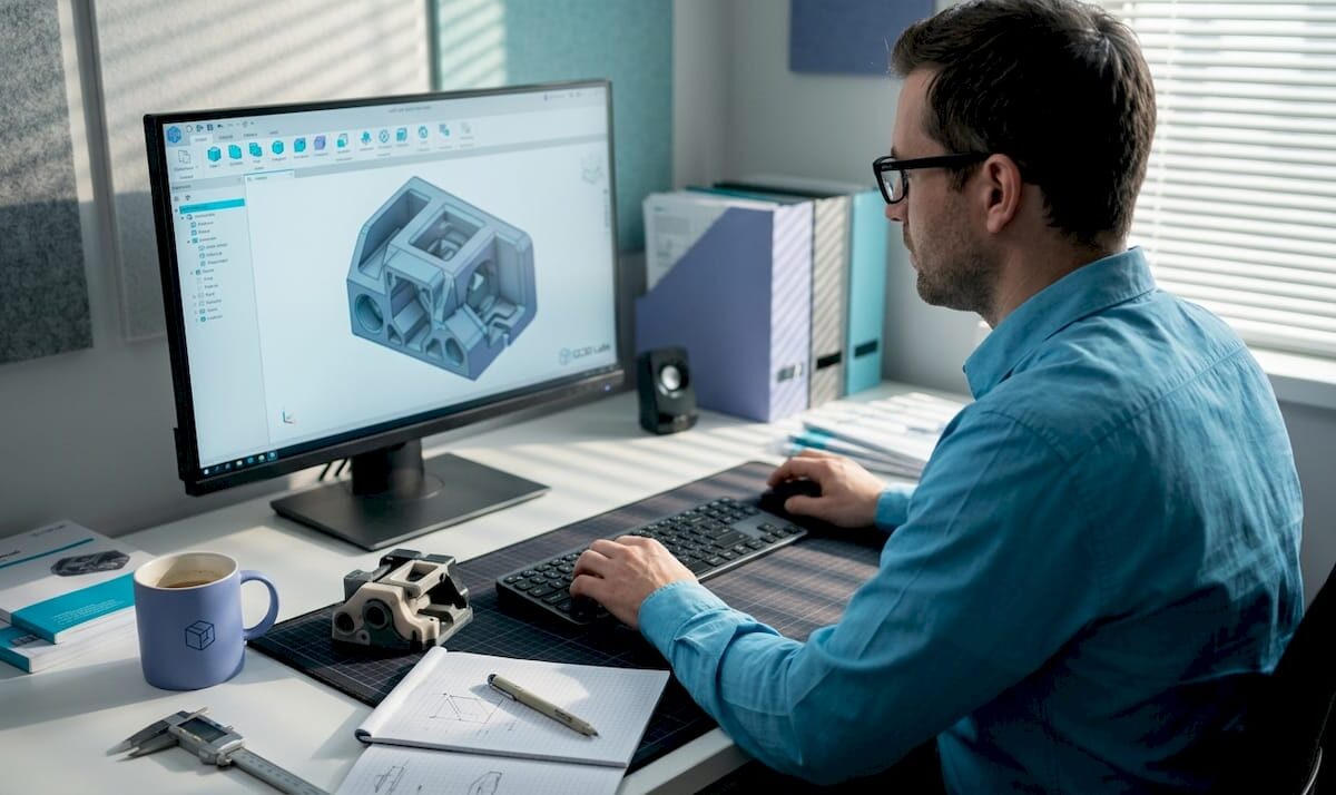
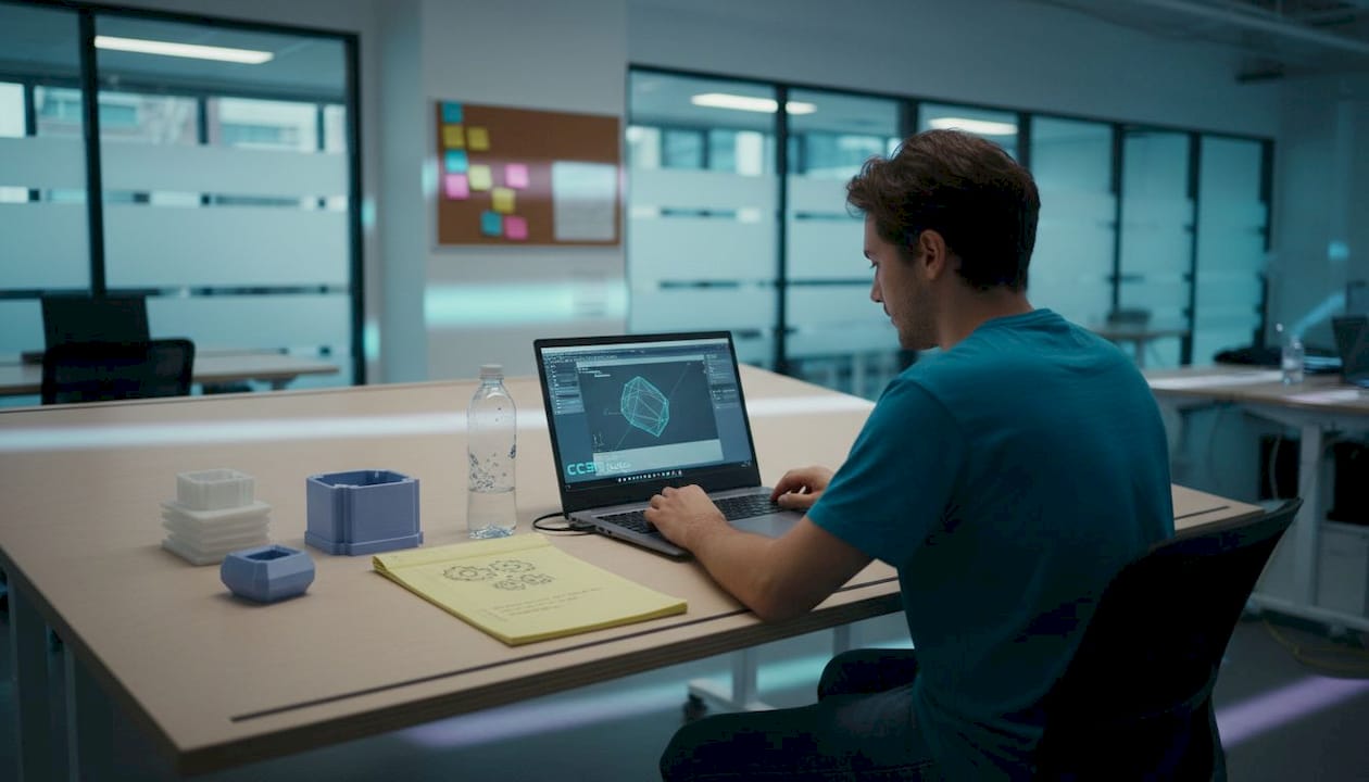
Engineer editing CAD model in workspace

How CAD integration drives 3D printing precision


TL;DR:

  • CAD design decisions directly influence print quality, strength, and success in 3D printing.
  • Properly optimized CAD models reduce failures caused by mesh issues, overhangs, and unsupported geometries.
  • Mastering CAD workflows is more impactful for quality and efficiency than investing in expensive printers.

Even the most expensive FDM printer on the market cannot compensate for a poorly built CAD file. That counterintuitive reality catches a lot of product developers off guard, especially those who assume hardware upgrades are the fastest path to better prints. The truth is that CAD is the foundational step in every 3D printing workflow, converting your concept into a precise digital model that gets exported, sliced, and ultimately printed. Every tolerance, wall thickness, and mesh decision you make in CAD ripples forward into the physical part. Understanding that connection is what separates teams that iterate quickly from those stuck reprinting the same prototype three times.

Table of Contents

Key Takeaways

Point Details
CAD is foundational Every 3D print project’s success begins and ends with how well you design and optimize your digital CAD model.
Follow DfAM best practices Design for Additive Manufacturing rules like correct wall thickness and support planning prevent failed prints.
Optimize for performance Tweaking orientation, infill, and mesh within CAD boosts strength and reduces production time and cost.
Account for advanced issues Factoring in anisotropy and potential hybrid machining from the CAD stage yields better functional parts.
Invest in CAD expertise Skillful CAD work typically enables more innovation and reliability than investing in costly printers alone.

How CAD shapes the 3D printing process

CAD, or computer-aided design, is the software environment where your idea becomes a geometric, measurable model. It is not simply a drawing tool. In the context of 3D printing, CAD determines whether a part is even printable, and at what level of accuracy it will come out of the machine.

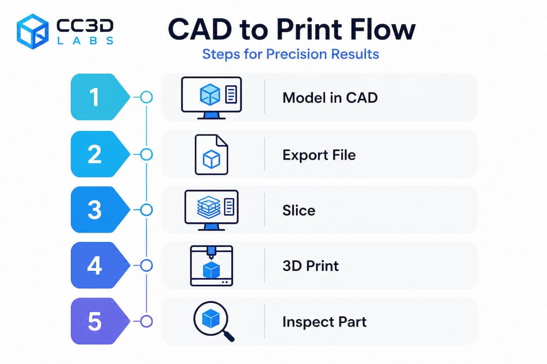
The workflow runs like this: you design a 3D model in CAD, export it as a machine-readable file, feed that into slicing software, and the slicer generates the toolpath your printer follows. The most common export format is STL (stereolithography), which approximates curved surfaces using triangular mesh facets. Higher triangle density produces smoother curves but inflates file size. Other formats like 3MF and STEP carry additional metadata such as color, scale, and assembly information, making them increasingly preferred for complex production jobs.

Infographic showing CAD to 3D printer workflow steps

Here is why this matters in practice. An STL file with too-low resolution will print visible faceting on a curved medical enclosure or an aerodynamic intake. A mesh with non-manifold edges, gaps, or overlapping surfaces creates ambiguous geometry that slicers interpret incorrectly, leading to missing walls or hollow sections in a part that was supposed to be solid. Understanding the best CAD file formats for your specific workflow prevents a whole category of upstream errors before you ever hit print.

What CAD controls in 3D printing:

  • Part geometry, including all wall thicknesses and internal features
  • Surface topology and mesh quality
  • Assembly fit and tolerancing
  • Export format and resolution
  • Whether geometry is valid and printable without repair

“CAD directly impacts print quality, precision, and success. The wrong design decisions create failures that no printer setting can fix.”

The key shift in mindset is treating CAD not as a design tool but as a manufacturing specification tool. Every decision you make in the model is a decision about how the printer will behave layer by layer.

Key CAD methodologies for print success

Design for additive manufacturing, commonly called DfAM, is the discipline of shaping CAD decisions around the specific constraints and advantages of 3D printing. It is distinct from design for injection molding or machining, and applying the wrong framework causes obvious problems.

The

core DfAM practices every engineer should internalize include minimum wall thickness guidelines, overhang management, hole geometry, stress-relief features, and watertight meshes. These are not aesthetic preferences. They are parameters grounded in how filament or resin behaves during deposition or curing.

Critical DfAM parameters for FDM and SLA:

  • Minimum wall thickness: 1.0 to 2.0mm for FDM, 0.5 to 1.0mm for SLA
  • Overhang angle: Keep overhangs under 45 degrees from vertical to avoid drooping without supports
  • Teardrop holes: Orient vertical holes as teardrops to eliminate bridging failure at the top
  • Fillets and chamfers: Add internal fillets to corners to reduce stress concentrations and delamination risk
  • Mesh integrity: All surfaces must form a closed, watertight volume with no holes, gaps, or non-manifold edges
DfAM Parameter FDM Guideline SLA Guideline
Minimum wall thickness 1.2 to 2.0mm 0.5 to 1.0mm
Overhang angle Less than 45° Less than 30°
Minimum hole diameter 2.0mm 0.5mm
Fillet radius 0.5mm minimum 0.3mm minimum
Mesh type Watertight, manifold Watertight, manifold

When designing reliable prints, overhang management is often where teams stumble first. A bracket arm designed without awareness of the printer’s 45 degree threshold will require heavy supports that are time-consuming to remove and often leave cosmetic or dimensional defects on the contact surface. Redesigning the arm with a chamfer instead of a perpendicular face eliminates the support entirely.

Technician inspecting 3D print overhang issues

Pro Tip: When your geometry calls for a hole parallel to the build plate, model it as a teardrop shape pointing upward. The slicer will bridge the flat underside cleanly, and you end up with a more accurate bore than a standard circle produces.

Watertight meshes deserve special attention because this is where many imported or converted models fail silently. A mesh that looks correct in CAD may contain microscopically open surfaces. Slicers either crash or generate malformed toolpaths from non-manifold geometry. Running a mesh repair check inside your CAD tool or a validator like Meshmixer before export is not optional on mission-critical parts. For more on how these rules translate into real outcomes, explore the print accuracy tips that guide our own production process.

Optimizing CAD files for stronger, more efficient parts

Once your model is geometrically sound and DfAM-compliant, the next layer of optimization focuses on performance. This is where CAD decisions directly affect mechanical strength, print time, and material cost simultaneously.

Step-by-step CAD optimization for production-ready parts:

  1. Analyze part orientation in the slicer before finalizing the model. The axis of greatest load should align with the XY build plane, not the Z axis.
  2. Identify all surfaces that would require supports and explore geometry modifications to minimize them.
  3. Choose between solid and lattice infill based on the part’s function. Load-bearing parts often need solid infill; structural housings can use gyroid or honeycomb lattice patterns without sacrificing rigidity.
  4. Set layer thickness based on your precision requirements. Thinner layers produce stronger, more accurate parts at the cost of print time.
  5. Confirm mesh resolution is high enough to accurately represent curves without over-bloating file size.
  6. Validate thermal settings in your CAD metadata or production notes if you are working with engineering-grade filaments like Nylon or PETG.

CAD pre-processing optimization analyzes part orientation to minimize supports, cut material use, and reduce print time. Tools like Siemens NX with DfAM modules can compare solid versus lattice infill configurations computationally, letting you evaluate structural performance before a single gram of filament is consumed.

The data on this is compelling. Empirical research on FDM shows that optimized CAD-printed PLA cubes reach compressive strength values around 31.4 MPa. Layer thickness is the single most influential parameter: a low layer thickness of 0.15mm combined with a high extruder temperature of 225 degrees Celsius produces the maximum combined performance index across strength and surface quality.

Configuration Layer Thickness Extruder Temp Compressive Strength
Optimized 0.15mm 225°C ~31.4 MPa
Standard 0.2mm 210°C ~24 MPa
Low quality 0.3mm 200°C ~18 MPa

This is not trivial. A 30 to 40 percent difference in part strength comes from CAD and process settings, not from switching to a more expensive printer. When you are developing functional prototypes or end-use parts, refer to manufacturing-grade methods to understand how these optimization principles apply at production scale. For teams new to this level of detail, a step-by-step prototype guide can bridge the gap between concept and validated part.

Advanced considerations: Anisotropy, lattices, and hybrid processes

For engineers pushing the mechanical limits of 3D printed parts, three topics demand serious CAD-level attention: anisotropy, lattice structure design, and hybrid manufacturing workflows.

Anisotropy refers to the directional variation in mechanical properties that FDM parts exhibit by default. Because material is deposited in layers, bonds between layers are inherently weaker than bonds within a layer. FDM anisotropy can result in a strength drop of up to 70 percent in the Z axis compared to the XY plane. In CAD terms, this means that a part carrying tensile loads in the Z direction will fail at a fraction of the force a same-geometry machined metal part would tolerate.

The CAD response to anisotropy is deliberate orientation strategy. You map the dominant load vectors onto the XY plane during the design phase, not as an afterthought during slicing. In some cases, this means splitting a part into two components that are printed separately and bonded, rather than printing a single piece in an unfavorable orientation.

Lattice structures offer compelling advantages for weight reduction in aerospace, robotics, and medical devices. A gyroid lattice can maintain 70 to 80 percent of a solid part’s stiffness at 40 percent of the material volume. However, internal lattices create a support removal challenge that most standard post-processing tools cannot address cleanly.

Key points for CAD-level lattice design:

  • Define lattice cell size relative to nozzle diameter. Cells too small for the nozzle diameter will not print accurately.
  • Avoid lattice regions adjacent to mating surfaces that require dimensional precision.
  • Include drain holes in enclosed lattice zones to allow powder or resin evacuation in SLS and SLA processes.
  • Simulate load distribution before committing to a cell pattern. Not all lattice geometries perform equally under all load types.

Pro Tip: If you are designing a lattice for structural lightweighting, run an FEA (finite element analysis) pass inside your CAD tool before exporting. Topology optimization outputs combined with lattice infill give you a data-backed starting point instead of an educated guess.

Hybrid manufacturing recognizes that 3D printing alone does not always achieve the tight tolerances that functional parts require. Post-print CNC machining on bearing surfaces, threaded holes, and mating faces is increasingly common in precision applications. This means your CAD model needs to include machining allowances, datum references for fixturing, and feature flags that differentiate printed surfaces from machined surfaces. Planning these details in CAD from the start avoids costly reprints and setup errors downstream. For guidance on balancing print complexity with production volume, the tips for low-volume production are directly applicable here.

Our take: Why great CAD still trumps expensive printers

We work with product developers and engineers across a wide range of industries, and one pattern shows up consistently: teams that struggle with print quality are almost always struggling with CAD quality first. The printer is rarely the problem. A printer running with a well-optimized, DfAM-compliant file will outperform a top-shelf machine running a poorly constructed model every single time.

The uncomfortable reality is that most 3D print failures, including warping, delamination, dimensional inaccuracy, and weak mechanical performance, are downstream effects of decisions made in CAD, not printer malfunctions. Engineers who understand DfAM, mesh integrity, orientation strategy, and material behavior at the design stage spend dramatically less time troubleshooting and iterating. Their first print is often their last prototype before production.

There is also an important counterargument worth naming honestly. As hybrid manufacturing research makes clear, 3D printing excels at prototyping and low-volume production, but scaling to true production volumes for complex, precision-critical parts often still requires integration with traditional machining. CAD skills become even more valuable in that hybrid context because you are designing simultaneously for two very different manufacturing constraints.

Our recommendation is this: invest the time to master your CAD workflow before you consider upgrading your printer. The return on that investment is higher, more transferable, and more immediately visible in print outcomes. Understanding why quality matters at the design stage is what gives you repeatable results, not a more expensive machine.

Ready to leverage pro-level CAD and 3D printing?

Putting these CAD principles into practice requires both expertise and the right production environment. At CC 3D Labs, we specialize in bridging the gap between your digital design and a precisely printed physical part, whether you are developing a functional prototype or moving into batch production.

https://cc3dlabs.com

Our team works directly with professional 3D printing services optimized for engineering-grade accuracy, reviewing CAD files for DfAM compliance before a single layer is printed. Whether you need on-demand prototypes with fast turnaround or guidance on production-ready part design, we bring the technical depth to make your designs work the first time. Browse our CAD project gallery to see the range of complex, precise parts we produce for clients across industries, and reach out for a free estimate when you are ready to move from concept to part.

Frequently asked questions

Why is CAD so important in 3D printing?

CAD provides the exact digital blueprint that determines whether a part is printable, how accurate it will be, and whether it will meet mechanical requirements. As foundational workflow research confirms, poor CAD decisions lead directly to failed or inaccurate prints regardless of printer quality.

Which CAD features matter most for strong 3D printed parts?

Wall thickness, mesh watertightness, part orientation, and well-placed fillets are the most critical design factors. DfAM practice guidelines specify minimum wall thickness of 1 to 2mm for FDM, with overhangs kept under 45 degrees and fillets applied at all internal corners to reduce stress.

How does CAD affect print time and material use?

Part orientation and infill strategy are the two biggest levers. Pre-processing optimization tools can compare solid versus lattice infill configurations and evaluate orientation options to minimize support structures, material consumption, and total print time before the job starts.

Do I always need to redesign parts in CAD for 3D printing?

Nearly always, yes. Parts designed for injection molding or machining often include geometry that is unprintable or structurally weak when 3D printed. Adapting designs to 3D printing-specific rules in CAD is essential for achieving reliable dimensional accuracy and mechanical performance.

What are the biggest challenges with CAD in 3D printing?

The most common challenges are managing anisotropic mechanical properties through orientation strategy, ensuring fully watertight mesh geometry, and designing parts that account for hybrid post-print machining. FDM anisotropy alone can reduce Z-axis strength by up to 70 percent when load alignment is not addressed in CAD.