
TL;DR:
- Most engineers mistakenly assume that any 3D scan qualifies as archival, which can jeopardize long-term reuse. Achieving true archival 3D scanning requires detailed measurement records preserved in durable, open formats, alongside comprehensive documentation and calibration data. Proper workflow planning, including defining coordinate systems, controlling scan conditions, and maintaining metadata, is essential to ensure digital assets remain useful for decades.
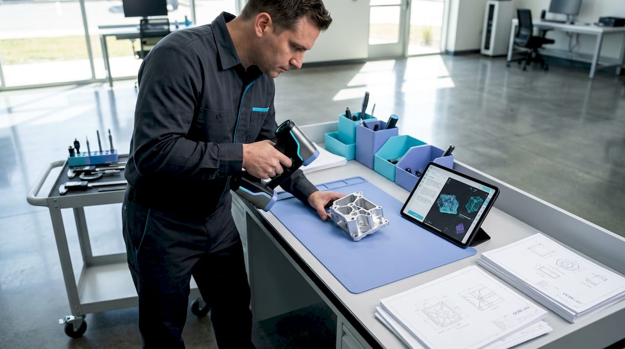
Most engineers assume that any 3D scan is an archival scan. That assumption quietly kills product development programs. True archival 3D scanning means capturing high-fidelity 3D measurements of a physical object and preserving the resulting datasets, including raw scan data, derived models, and metadata, in durable, long-term formats designed for reuse years or even decades later. For product developers and manufacturers, that distinction is not academic. It determines whether your digital record can actually drive a reprint, a tolerance audit, or a design iteration in five years without starting from scratch.
Table of Contents
- Archival 3D scanning: Definition and core concepts
- Critical workflow elements for archival 3D scanning
- Quality control: Materials, surfaces, and scan acceptance
- Archival file formats and long-term data preservation
- The uncomfortable truth: Why archival 3D scanning rarely succeeds without planning
- Next steps: Partnering for archival 3D scanning and prototyping success
- Frequently asked questions
Key Takeaways
| Point | Details |
|---|---|
| Engineered for reuse | Archival 3D scanning creates precise digital records that enable reliable prototyping and manufacturing, even decades later. |
| Workflow and validation matter | Careful planning, calibration, and documentation make the difference between true archival utility and data loss. |
| No single file standard | Long-term success relies on preserving both raw and interoperable files, plus metadata about methods and conditions. |
| Quality depends on application | Material, surface, and intended use all impact how you capture and accept 3D scan data for the archive. |
Archival 3D scanning: Definition and core concepts
With a shared understanding of why preservation matters, let’s clarify exactly what archival 3D scanning entails and why it differs from what most people picture.
An archival 3D scan is not simply a mesh you can rotate on screen. It is a structured measurement record built to survive software migrations, personnel changes, and years of engineering reuse. That distinction separates it from the ad-hoc scans common in hobbyist workflows or single-use inspection tasks, where the goal is a quick visualization, not long-term data fidelity.
Professional practice treats scans as measurement records that feed controlled workflows, including control networks, traceable deliverables, and field records, not just visualization models. This is precisely the standard that product engineers need to adopt.
The core concepts behind archival scanning include:
- High-resolution capture: Point cloud density sufficient to resolve the finest functional features on your part
- Traceable coordinate systems: Every dataset is registered to a defined spatial reference, so geometry is reproducible
- Calibration documentation: The scanner’s measurement uncertainty is recorded, not assumed
- Metadata preservation: Capture date, operator, equipment, ambient conditions, and processing parameters accompany every dataset
- Controlled deliverable formats: Both raw scan files and processed derivatives are retained separately
“Archival quality is not a feature of the scanner. It is a property of the workflow, the documentation, and the intent behind the capture.”
Understanding design accuracy and prototyping requirements from the start lets your team define what “archival” actually means for your specific use case, whether that is heritage documentation, reverse engineering, or first-article inspection.
Critical workflow elements for archival 3D scanning
Understanding the goals of archival scanning, we next examine what it takes, in practice, for a scan to achieve those standards.

The most common failure mode in archival scanning programs is treating the scan session itself as the entire workflow. In reality, the scan session is just the first step. What transforms raw point cloud data into a true archival resource is the controlled measurement package that surrounds it.
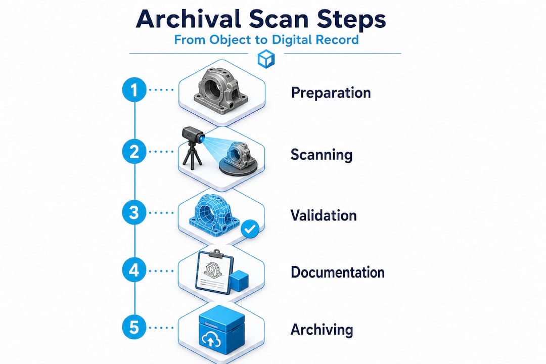
Your scanning checklist for accuracy should address five non-negotiable workflow elements:
- Coordinate system definition: Establish a fixed reference frame before scanning begins. Use physical control targets, monuments, or reference artifacts that can be reproduced in future sessions. Without a defined coordinate system, your scan is a floating geometry with no spatial anchor.
- Registration and control strategy: Document how individual scan positions were merged. Record the targets used, the registration algorithm, and the resulting residual errors. This documentation allows future engineers to verify alignment or re-register datasets from scratch if needed.
- Calibration and uncertainty documentation: Every scanner has a stated accuracy specification, but real-world accuracy depends on surface properties, distance, angle of incidence, and environmental conditions. Record the calibration certificate, the pre-capture validation routine, and any uncertainty estimates specific to the captured object.
- Raw file preservation: Never discard the original point cloud or structured scan data. Raw files are the ground truth. Processed meshes and derivative CAD models are interpretations. If your processing software introduces artifacts, the raw data is your only path to recovery.
- Metadata and provenance records: Log everything that a future engineer would need to understand the capture: scanner model, firmware version, resolution settings, ambient temperature, lighting conditions, and the name of the person who performed the scan.
Pro Tip: Create a standardized scan log template and require it to be completed before any scan session is closed out. Treat it like a lab notebook entry. Future engineers will thank you, and so will your quality management system.
The table below summarizes the key deliverables in a properly structured archival measurement package:
| Deliverable | Format | Purpose |
|---|---|---|
| Raw point cloud | Proprietary + open (e.g., .e57, .las) | Ground truth reference |
| Registered scan assembly | Project file + exported .e57 | Reproducible spatial reference |
| Processed mesh | .obj, .stl, or .ply | Engineering and manufacturing use |
| Calibration record | PDF or structured document | Uncertainty traceability |
| Coordinate system definition | Report or README file | Spatial context for future users |
| Metadata log | Structured text or database entry | Provenance and repeatability |
Following documentation strategies for workflows used in other precision industries reveals a pattern: the teams that document obsessively are the teams that can reproduce results years later without heroic reverse engineering efforts.
A high quality scan process also accounts for fixture design, lighting control, and surface preparation before the scanner is ever switched on. These upstream decisions directly determine whether your archived data is usable or merely stored.
For teams that want to access professional-grade equipment and validated workflows without building an in-house lab, partnering with a dedicated 3D scanning lab dramatically reduces the risk of workflow gaps.
Quality control: Materials, surfaces, and scan acceptance
With the core workflow defined, the next challenge lies in managing variable scan quality and ensuring reliable results across different object types.
Here is a fact that surprises many engineers early in their archival scanning programs: the scanner model matters far less than the strategy around it. Surface characteristics and acquisition conditions fundamentally change what is achievable in terms of accuracy, completeness, and dimensional fidelity. As a result, archival success depends on capture strategy, validation, and fit-for-purpose uncertainty, not only the scanner model.
The materials and surfaces that cause the most trouble in engineering environments include:
- Highly polished or mirror-finish metals: Structured light and laser scanners struggle with specular reflections, producing noise or gaps in the point cloud
- Transparent or translucent materials: Glass, clear polycarbonate, and acrylic are nearly invisible to most scanning technologies without surface treatment
- Carbon fiber and dark matte composites: High light absorption causes inconsistent returns and reduced point density
- Small radii and sharp internal corners: Occlusion and beam divergence limit coverage in tight geometries
- Large flat surfaces: Can look easy but are prone to alignment drift during stitching if control targets are insufficient
| Surface type | Common challenge | Recommended strategy |
|---|---|---|
| Polished metal | Specular reflection, point cloud noise | Apply matte scanning spray or use photogrammetry targets |
| Transparent plastic | Scanner cannot detect surface | Apply temporary matte coating, remove after scanning |
| Dark composite | Low return signal, incomplete coverage | Increase scan exposure or apply reference dots |
| Complex internal geometry | Occlusion, coverage gaps | Multi-angle capture with validated coverage maps |
| Large flat panels | Alignment drift during stitching | Dense target field with certified reference distances |
Pro Tip: Define your acceptance criteria before you scan, not after. Set minimum point density thresholds, maximum allowable deviation from reference measurements, and coverage completeness requirements for each part type. This prevents the common situation where a scan session is declared “done” based on visual inspection of the mesh rather than verified measurement performance.
“A scan that looks complete on screen and a scan that is dimensionally complete are not the same thing. Only your acceptance criteria tell the difference.”
Achieving scan quality on engineering parts with challenging surfaces often requires a combination of technologies, structured light for geometry, photogrammetry for reference targets, and contact measurement for ground-truth validation on critical features. No single method covers every scenario, and the importance of 3D prototyping quality becomes apparent the moment a downstream manufacturing process depends on a scan that was never properly validated.
Archival file formats and long-term data preservation
Reliable scanning and quality control are just the start. To realize the enduring value of your scans, you must think strategically about file formats and data management.
One of the most common misconceptions is that choosing the right file format is a single decision made at the end of a scan session. In reality, format strategy needs to be baked into your workflow from day one.
Archival 3D preservation practices commonly emphasize retaining original, raw scan data and using open or interoperable formats for long-term access, while acknowledging there is no single universally agreed archival file format. That means your format strategy must be deliberately constructed rather than defaulted into.
Best practices for long-term data preservation include:
- Retain raw master files: Keep the original capture files in the scanner’s native format alongside exported open formats. Native formats contain the most complete data, while open formats ensure future accessibility.
- Use a dual-track approach: Maintain one copy in the most complete format available (often proprietary) and a second copy in a widely readable open format such as .e57 for point clouds or .obj and .ply for meshes.
- Store metadata separately and explicitly: Do not rely on metadata embedded in the file header alone. Write a separate README or structured document that captures every piece of provenance information.
- Version your derivative models: When you process a raw scan into a mesh or CAD model, keep a record of what processing steps were applied and what software version was used.
- Plan for format migration: No format is permanent. Schedule periodic reviews of your archive to assess whether stored formats remain accessible with current software, and migrate to updated formats before the old ones become unreadable.
| Format | Type | Strengths | Limitations |
|---|---|---|---|
| .e57 | Point cloud (open) | Widely supported, stores metadata | No mesh representation |
| .las / .laz | Point cloud (open) | Common in survey workflows | Limited metadata fields |
| .ply | Mesh (open) | Stores color and normals | Less common in CAD workflows |
| .obj | Mesh (open) | Universal readability | No intrinsic coordinate metadata |
| .stl | Mesh (open) | Universal for manufacturing | No color, limited precision |
| Native formats (.zprj, .fls, etc.) | Proprietary | Maximum data fidelity | Software-dependent, risk of obsolescence |
Understanding the full landscape of top CAD file formats helps teams make informed decisions about which derivatives to produce and which formats will survive software upgrades over a ten-year horizon.
The uncomfortable truth: Why archival 3D scanning rarely succeeds without planning
Armed with best practices, let’s take a candid look at the rarely discussed pitfalls and what separates archival success from irretrievable data loss.
Most archival 3D scanning programs fail quietly. They do not fail dramatically with error messages or system crashes. They fail years later when an engineer opens a scan archive and finds that the metadata is missing, the coordinate system was never documented, the software that created the native files is no longer available, and the raw data was overwritten to save storage space. At that point, the “archive” is just a collection of orphaned meshes.
The root cause is almost always the same: teams treated archival scanning as a data collection task rather than an engineering discipline. Scanning is the physical act. Archival scanning is the system of decisions, documentation, and maintenance that makes those scans permanently useful.
Because there is no single universal archival 3D file format, engineers need to implement a dual track strategy, retaining raw and master files alongside interoperable derivatives, and preserving metadata and provenance so future teams can reconstruct the intended geometry and processing parameters without guesswork.
The mindset shift required here is significant. Stop thinking of your scan archive as a file folder and start thinking of it as a controlled measurement library. Every entry in that library should be retrievable, understandable, and reproducible by someone who was not in the room when the scan was captured.
What we have seen consistently at CC 3D Labs is that teams who invest in upfront planning, defining their acceptance criteria, establishing their coordinate systems, and committing to their dual-track format strategy before the first scan session, build archives that actually get used. Teams that treat these steps as optional administrative overhead end up rebuilding scans from scratch at exactly the wrong moment, typically when a key product is facing a design change or a regulatory audit.
A commitment to innovation in product development means treating your digital records with the same rigor you apply to your physical parts. Your scan archive is a manufacturing asset. Protect it accordingly.
Next steps: Partnering for archival 3D scanning and prototyping success
For product developers who are ready to move from theory to practice, the fastest path to a functional archival scanning program is partnering with a lab that already understands the nuances of measurement-grade capture and long-term data management.

CC 3D Labs provides metrology-grade 3D scanning lab services near Philadelphia, serving product developers and engineering teams who need scans that are genuinely fit for manufacturing, not just for viewing. Our workflows address coordinate system setup, calibration documentation, multi-format deliverables, and provenance records as standard practice, not add-ons. Whether you are reverse engineering a legacy component, creating a first-article inspection baseline, or building a long-term digital archive for a product line, we can structure a scanning program that meets your specific engineering requirements. Explore our scanning for accuracy and prototyping capabilities, or browse the full range of our 3D printing services to see how scanning and fabrication work together in a single, integrated workflow.
Frequently asked questions
What makes a 3D scan “archival” compared to a regular scan?
An archival 3D scan is a high-fidelity measurement record preserved with metadata, calibration documentation, and traceable coordinate systems in open formats designed for reliable reuse over years or decades, rather than a one-time visualization output.
Is there a universal file format for archival 3D scans?
No single standard exists. Best practice is to maintain raw master files alongside interoperable open-format derivatives such as .e57 for point clouds and .ply or .obj for meshes, ensuring future accessibility regardless of software changes.
What factors most affect the accuracy of an archival 3D scan?
Surface properties, lighting conditions, and scanner angle all influence results, but archival success ultimately depends on the capture strategy, validation protocol, and fit-for-purpose acceptance criteria applied to each specific object and application.
How can I ensure that my 3D scan data will still be usable in ten years?
Store original raw data and processed derivatives in open or widely supported formats, pair them with explicit metadata documentation, and schedule periodic format migration reviews to prevent format obsolescence before it becomes a problem.