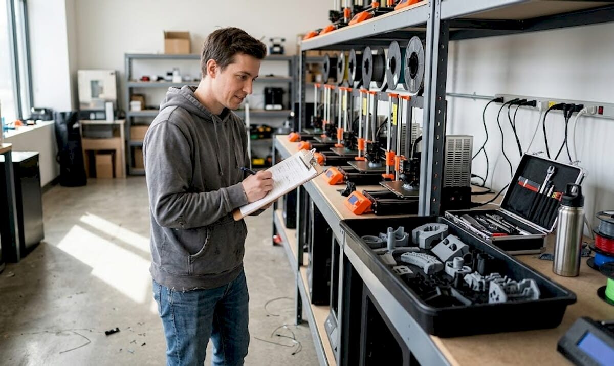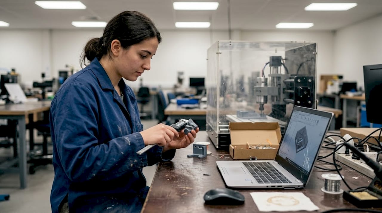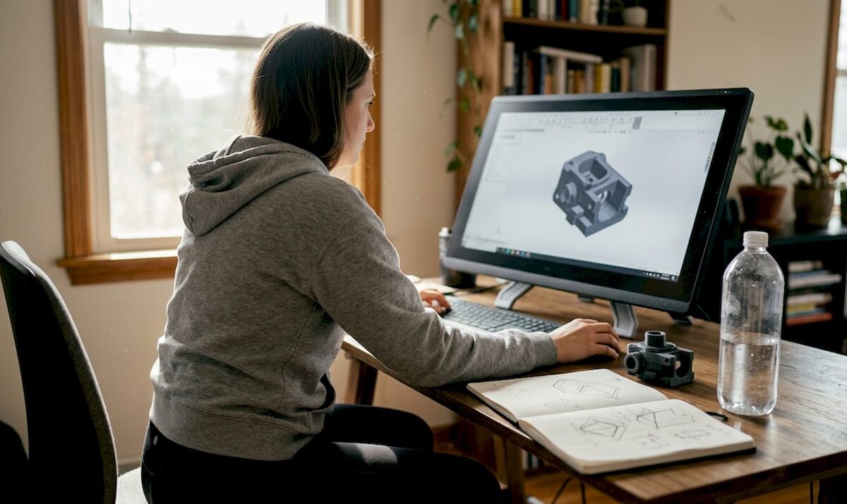
Designer reviewing online 3D printing estimate

Get precise online estimates for custom 3D printing


TL;DR:

  • Online quoting speeds up 3D printing workflows and helps with rapid design decisions.
  • Automated estimates are generally accurate for standard geometries but less reliable for complex features.
  • Preparing models carefully and validating quotes with manual reviews can improve cost accuracy and project success.

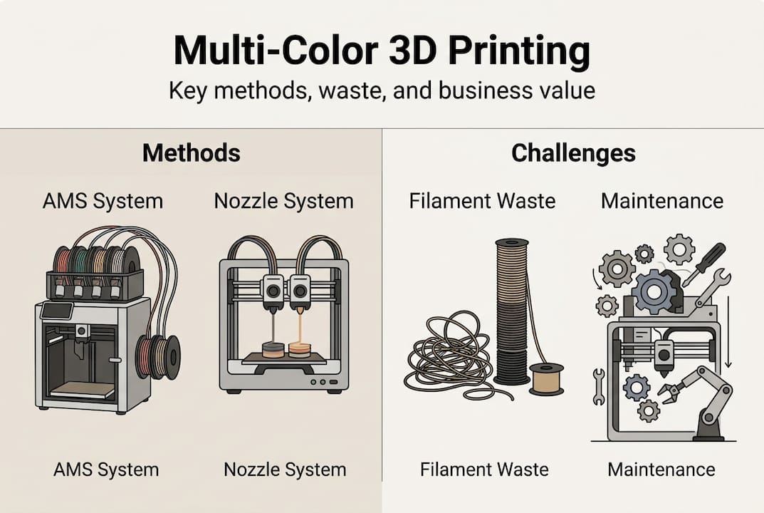
Waiting three days for a quote when your prototype deadline is tomorrow is not a workflow problem. It’s a competitive disadvantage. Traditional manual quoting slows engineering cycles, creates budget uncertainty, and forces developers to guess at costs during the most critical design phases. Instant quoting systems automate pricing by analyzing uploaded STL files, material choices, print time, and part complexity in seconds. But speed comes with trade-offs. This guide breaks down how online estimates work, where they fall short, and the practical strategies you can use to get numbers you can actually build a budget around.

Table of Contents

Key Takeaways

Point Details
Speed boosts workflow Instant online estimates slash prototyping delays and empower rapid engineering iteration.
Check itemized costs Always review the detailed breakdown—material, machine, labor, post-processing—for transparency and accuracy.
Know quoting limits Complex geometries and post-processing often require manual review, so buffer for hidden costs.
Design for accuracy Optimizing designs for quoting—minimizing supports and overhangs—produces more reliable instant estimates.
Benchmark for best value Compare multiple quoting platforms and ask for engineer reviews to ensure cost and quality alignment.

How online estimates transform 3D printing workflows

An online estimate, sometimes called an instant quote, is an automated pricing system that reads your 3D model file and returns a cost breakdown without human intervention. You upload a file, select a material and finish, and the platform calculates price based on volume, geometry, and machine parameters. The result arrives in seconds rather than days.

For product developers and engineers, this changes everything about early-stage design. You can test five material options in five minutes. You can compare a solid infill against a lightweight lattice structure and see the price difference immediately. Online estimators accelerate prototyping by providing immediate feedback on design changes, material trades, and quantity discounts. That feedback loop is what makes iterative design actually fast.

Infographic showing 3D print online quote process

Manual quoting, by contrast, typically takes 24 to 72 hours per request. For a team running ten design iterations per week, that delay compounds fast. Shapeways instant quoting platforms have demonstrated that automated systems can reduce quote turnaround from days to under a minute for standard geometries. That is not a marginal improvement. It is a fundamentally different workflow.

Here are the most common use cases where online estimates deliver real value:

  • Rapid prototyping: Get cost feedback before committing to a design revision
  • Material comparison: Instantly compare PLA, PETG, ABS, and nylon pricing for the same geometry
  • Functional part production: Estimate unit economics for small batch runs before scaling
  • Design iteration: Adjust wall thickness, infill, or orientation and see cost impact in real time
  • Budget planning: Establish rough cost ranges early in the product development cycle

Pairing this speed with a solid optimizing CAD workflow process means your files are quote-ready before you even hit submit. The engineers who get the most out of instant quoting are the ones who treat file preparation as part of the design process, not an afterthought.

Demystifying 3D printing cost calculation: What’s in an online quote?

Most engineers treat the quote number as a black box. Understanding what’s inside it gives you real leverage. STL file parsing for volume, surface area, and bounding box forms the foundation of every automated estimate. From there, the system estimates print time using slicing simulation or heuristics, then applies a cost formula.

The standard formula looks like this: Material cost (weight × $/g) + Machine cost (hourly rate × print time) + Labor + Overhead + Markup. Each variable carries its own uncertainty. Material weight depends on infill density. Machine time depends on layer height and print speed. Labor and overhead vary by provider.

Engineer calculating 3D printing quote by hand

Here is a simplified example of how those components stack up for a mid-complexity functional bracket (illustrative industry numbers, not CC 3D Labs pricing):

Cost component Basis Example amount
Material 45g × $0.08/g $3.60
Machine time 2.5 hrs × $4.00/hr $10.00
Labor Setup and removal $5.00
Overhead Facility, utilities $3.00
Markup 30% $6.48
Total estimate $28.08

The quoting sequence for a custom part typically follows these steps:

  1. Upload STL file to the platform
  2. System parses geometry for volume, surface area, and bounding box
  3. Slicer simulation estimates print time and material usage
  4. Cost formula applies material, machine, labor, and overhead rates
  5. Markup is added and the estimate is returned to the user
  6. Optional: engineer review for flagged complex geometries

For a deeper look at how these numbers are assembled, the cost calculator guide breaks down the math behind each variable. Understanding itemized quoting breakdowns also helps you spot when a platform is bundling costs that should be line items.

Pro Tip: Always request an itemized cost breakdown rather than a single total. If a platform only shows you one number, ask for a manual review on any prototype that has thin walls, internal channels, or significant overhangs. Those features are where automated estimates lose accuracy fast.

Recognizing the limits: When online quotes fall short

Instant quoting is powerful, but it has a ceiling. Complex geometries can fail automated analysis entirely. Thin walls below 1.2mm, extreme overhangs, and internal lattice structures push most quoting algorithms into uncertain territory. The system either flags the file for manual review or, worse, returns a price that does not reflect the actual print difficulty.

Post-processing is the biggest blind spot. Post-processing costs can increase final invoices by 30 to 40 percent, and most instant quoting systems do not model this accurately. Support removal, sanding, painting, and inspection are labor-intensive steps that vary by part geometry in ways that are hard to automate.

Here is a quick comparison of instant quoting versus manual engineering review:

Factor Instant online quote Manual engineering review
Speed Seconds to minutes 24 to 72 hours
Transparency Variable High
Accuracy (standard parts) Good Excellent
Accuracy (complex parts) Poor to moderate Excellent
Post-processing included Rarely Usually
Cost Free or low May carry a fee

Common hidden costs that online estimates frequently miss include:

  • Support structure material and removal labor
  • Surface finishing (sanding, priming, painting)
  • Dimensional inspection and quality documentation
  • Failed print reprints (especially for complex geometries)
  • Expedited turnaround fees

For tips for accurate instant quoting on complex parts, the key is knowing when to escalate. If your part has features that would give a human engineer pause, an automated system will not catch them reliably. Reviewing instant quoting system alternatives can also reveal platforms with more robust manual review pipelines built into their workflows.

The cost drivers in 3D print quotes are more nuanced than most automated systems capture, particularly when functional performance requirements enter the picture.

How to get accurate online estimates: Practical engineering strategies

Getting a reliable estimate is not just about picking the right platform. It is about preparing your model and your process so the automated system has everything it needs to return a meaningful number.

Here are the key steps for reliable instant quoting:

  • Optimize your model first: Clean up non-manifold geometry, remove duplicate surfaces, and confirm wall thickness meets minimum print requirements before uploading
  • Select platforms with itemized breakdowns: Prioritize platforms with itemized breakdowns and engineer review options, especially for prototypes and functional parts
  • Request manual review for edge cases: If your part has overhangs greater than 45 degrees, thin walls, or complex internal geometry, flag it for human review
  • Compare multiple estimators: Run the same file through two or three platforms and compare results. Significant variance signals a part that needs manual attention
  • Use benchmark quoting calculators to cross-check: Independent calculators help you validate whether a platform’s estimate is in a reasonable range

Pro Tip: For prototypes, orient your model to minimize support structures before uploading. A part printed at a 45-degree angle often uses significantly less support material than one printed flat, and that directly reduces both material cost and post-processing labor. Small orientation decisions at the design stage translate into real savings in the estimate.

For functional parts, always benchmark your online quote against a manual review before committing to a production run. The CAD estimate form at CC 3D Labs allows you to submit files for review with specific functional requirements noted, which gives our team the context to catch cost variables an automated system would miss.

Also review quoting platform comparisons to understand which services offer the transparency and engineering support your project actually requires. Not all platforms are built for the same use cases, and choosing the wrong one for a functional part run can cost you more than the time you saved on quoting.

The engineering reality: Instant quotes vs. true costs

Here is something most online quoting platforms will not tell you: the number on your screen is a starting point, not a contract. We have seen engineers treat instant estimates as final budgets, only to face invoices that are 30 to 40 percent higher once post-processing and quality checks are factored in.

The math behind this is straightforward. Material is only 15 to 30% of total print cost. Machine time, labor, and failure rates (typically 5 to 10 percent for complex geometries) dominate the actual invoice. Instant quoting systems are optimized to calculate material and machine time accurately. They are not optimized for the human labor that happens after the print finishes.

The race-to-the-bottom pricing you see on some platforms is a red flag, not a deal. Providers who compete purely on quote price often cut corners on material quality, machine calibration, or post-processing thoroughness. For a display model, that might be acceptable. For a functional part that goes into a product, it is a liability.

Our recommendation for low-volume manufacturing tips is to always buffer your budget by at least 20 percent above the online estimate for functional part runs. For complex prototypes, budget for at least one reprint. Use the instant quote as a directional signal, then validate it with a manual review before finalizing your project budget. The engineers who do this consistently are the ones who hit their timelines without budget surprises. See how custom print job selection factors into getting the right service match for your specific application.

Level up your 3D printing workflow with trusted solutions

Applying these strategies is straightforward when you have a service provider who builds transparency into every quote. At CC 3D Labs, we offer both instant online estimates and detailed manual reviews for complex prototypes and functional parts.

https://cc3dlabs.com

Our 3D printing services are designed for product developers and engineers who need accurate numbers, not ballpark figures. Whether you are exploring printing prototypes and functional parts for the first time or managing a batch production run, our team provides itemized breakdowns that reflect real costs. Request a custom print quote today and see the difference that engineering-backed quoting makes for your project timeline and budget.

Frequently asked questions

How accurate are online estimates for 3D printing?

Online estimates are typically reliable for standard geometries but often underrepresent total costs for complex features or finishing work. Post-processing costs can increase final invoices by 30 to 40 percent above the initial automated quote.

What file formats are best for automated online quoting?

STL files are the standard for 3D print quotes because they provide the volume and geometry data needed for automated cost calculation. Parsing STL files for volume, surface area, and bounding box is the foundation of every instant quoting system.

Can online estimates factor in quantity discounts?

Yes, many instant quoting platforms adjust pricing automatically based on order quantity. Immediate feedback on quantity discounts is one of the strongest advantages of automated estimators for batch prototype planning.

How can I make my model easier to quote instantly?

Simplify your geometry by minimizing overhangs and support-heavy features, and choose an orientation that reduces material usage before uploading. Minimizing supports and overhangs early in the design process produces more reliable automated estimates and lower actual print costs.

Engineer checking 3D print in cluttered lab workspace

Key 3D Printing Trends Shaping Manufacturing in 2026


TL;DR:

  • The 3D printed nanomaterials market is expected to reach $1.2 billion by 2026, indicating manufacturing is shifting to core strategy.
  • Advanced nanomaterials like graphene and CNTs significantly enhance filament strength, widening application fields in aerospace, automotive, and medical sectors.
  • AI-driven processes improve quality, reduce waste, and democratize additive manufacturing, enabling smarter, more efficient workflows.

The 3D printed nanomaterials market is projected to hit $1.2B in 2026, and that number alone tells you something important: 3D printing is no longer a prototyping curiosity. It is becoming a core manufacturing strategy. For product developers and engineers, the next 12 months will bring real decisions about materials, process economics, AI integration, and supply chain design. Getting these calls right separates teams that ship better products faster from those still debating which printer to buy. This article breaks down the four most consequential trends shaping additive manufacturing in 2026 so you can act on them with clarity.

Table of Contents

Key Takeaways

Point Details
Nanomaterials boost strength Cutting-edge filaments with graphene and CNTs can make 3D-printed parts 50-200% stronger.
Material extrusion leads production FFF/FDM is now the most economical method for large-scale 3D printing, replacing more costly alternatives.
AI powers efficiency AI-driven automation is improving print quality, reducing defects, and making advanced manufacturing more accessible.
ROI shapes equipment choices Firms now choose 3D printing tools based on specific application ROI, not general capabilities.
Hybrid models enhance resilience Combining in-house 3D printing with expert partnerships strengthens supply chains and sustainability.

The rise of advanced materials and nanotechnology

Now that you see the market’s rapid escalation, let’s examine how new materials and nanotechnology are fundamentally changing what’s possible. The short version: filaments are getting dramatically stronger, and the applications that were once limited to metals are opening up to advanced polymers.

Nanomaterial-infused filaments are boosting tensile strength by 50 to 200%, depending on the base material and the additive used. Graphene and carbon nanotubes (CNTs) are the two most significant contributors here. Graphene adds conductivity and stiffness without adding meaningful weight. CNTs improve impact resistance and thermal stability, which matters enormously in aerospace brackets, automotive housings, and medical device enclosures.

Infographic showing 2026 3D printing trends overview

Beyond filament, artificial intelligence is now being used to design entirely new alloys from scratch. An AI-designed Fe-15Cr steel achieves 1,713 MPa tensile strength with 15.5% elongation, a combination that outperforms many conventionally developed steels. This is not a lab curiosity. It signals that the material design process itself is being automated, compressing the timeline from concept to production-ready specification.

Here is a quick look at how nanomaterial-enhanced filaments compare across key performance categories:

Material type Tensile strength gain Key benefit Primary application
Graphene-infused PLA Up to 50% Conductivity + stiffness Electronics housings
CNT-reinforced nylon Up to 150% Impact resistance Automotive components
Carbon fiber PEEK Up to 200% Thermal stability Aerospace brackets
Nano-silica ABS Up to 80% Surface hardness Medical device casings

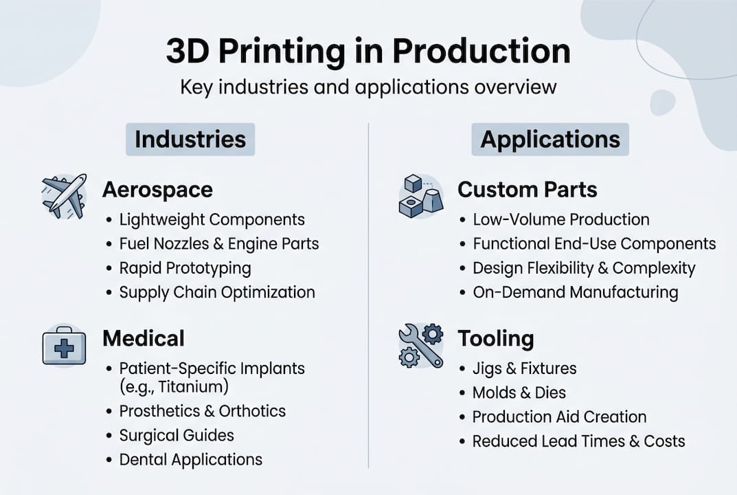
The industries moving fastest on this are aerospace, automotive, and medical devices. Each of these sectors demands parts that perform under stress, heat, or sterile conditions. Nanomaterial filaments are starting to meet those bars in ways standard polymers never could.

Key applications driving nanomaterial adoption:

  • Lightweight structural brackets replacing aluminum in aircraft interiors
  • Thermally stable housings for under-hood automotive sensors
  • Biocompatible, high-strength implant guides in surgical planning
  • Electrically conductive enclosures for embedded electronics

Pro Tip: If you are evaluating advanced filaments for a functional part, always request material data sheets with tensile, flexural, and thermal specs. A vendor who cannot provide them is not ready for production-grade work. Our filament 3D printing guide walks through what to look for when selecting materials for real-world applications.

Material extrusion and the economics of 3D printing farms

Material innovations are only as useful as the processes that make them practical. The economics of production are shifting too, especially in extrusion-based 3D printing. Fused filament fabrication (FFF), also called FDM, is gaining serious ground as a production technology, not just a prototyping tool.

Material extrusion is increasingly favored over SLS and MJF for large production farms because the economics simply work better at scale. Lower machine costs, cheaper feedstocks, and easier post-processing make FFF farms a compelling alternative for mid-to-high volume runs of functional parts.

High-filled polymers are a big part of this story. When you load a nylon or PEEK matrix with 30 to 50% carbon fiber or glass fiber, the resulting part can replace die-cast aluminum or zinc in many applications. The weight savings are real, and so is the cost reduction when you factor out tooling.

Here is how FFF stacks up against powder-based processes for production use:

Factor FFF/FDM SLS MJF
Machine cost Low to medium High High
Material cost per kg Low Medium to high Medium to high
Post-processing complexity Low High Medium
Scalability (farm model) Excellent Limited Limited
Part isotropy Moderate High High
Best for Functional parts, tooling Complex geometries High-detail production

Large-format additive manufacturing (LFAM) is also expanding the FFF envelope. Systems that extrude high-filled polymers at scale are now being used for composite tooling, jigs, fixtures, and even mold cores. This is a direct replacement for CNC-machined tooling in some workflows, with lead times measured in hours rather than weeks.

Four reasons manufacturers are building FFF production farms in 2026:

  1. Faster iteration cycles without retooling costs
  2. On-demand production that reduces inventory overhead
  3. Compatibility with advanced composite filaments
  4. Lower operator skill requirements compared to powder-bed systems

If you are still deciding which process fits your production goals, reviewing choosing the right 3D printing method can sharpen that decision. And if you are working at lower volumes, low-volume manufacturing tips covers the practical side of making FFF work efficiently at smaller batch sizes.

AI-driven automation and smarter additive manufacturing

As production scales, ensuring quality and efficiency becomes crucial. Here’s where AI is accelerating change in 3D printing. The technology is moving from a novelty to a genuine process control tool, and the impact is measurable.

Technician monitors AI-driven 3D printing factory

AI optimizes print paths and detects print anomalies, improving reliability across complex geometries and multi-material builds. This matters because traditional quality control in additive manufacturing has always been reactive: you print the part, inspect it, and scrap it if it fails. AI-driven monitoring catches problems mid-print, reducing waste and rework significantly.

Smaller powder particle sizes in powder-bed systems are also enabling smoother surfaces without additional finishing. When combined with AI-optimized scan paths, the result is a part that exits the machine closer to spec. That reduces post-processing time and cost, which is often where additive manufacturing loses its economic advantage.

Where AI is making the biggest difference in AM workflows:

  • Real-time layer inspection using computer vision to flag delamination or warping
  • Generative design tools that propose geometries optimized for both performance and printability
  • Predictive maintenance on print farms to reduce unplanned downtime
  • Automated support structure generation that minimizes material use

Pro Tip: When evaluating a 3D printing partner or in-house system, ask specifically about their quality control process. AI-assisted inspection is becoming a differentiator. If the answer is “we visually inspect after printing,” that is a flag for high-volume or critical-use parts.

“AI is lowering the entry barrier for in-house additive manufacturing,” making it practical for engineering teams without deep AM expertise to run reliable production workflows. (Source)

This democratization effect is significant. Teams that previously needed a dedicated AM specialist to manage process parameters can now rely on software-guided workflows. That does not eliminate the need for expertise, but it does lower the floor for getting started. For engineers exploring how 3D scanning integrates into quality-controlled workflows, achieving high-quality 3D scans covers the metrology side of the equation.

Sustainability, supply chain resilience, and the new AM business model

Digital transformation isn’t just about speed and quality. The business context is evolving as well, introducing new priorities for engineering leaders. Sustainability and supply chain flexibility are now core considerations in how companies structure their additive manufacturing programs.

Supply chain resilience and sustainability are driving adoption of additive manufacturing, with hybrid in-house and expert partnerships becoming the norm. The logic is straightforward: a distributed, on-demand production model is inherently more resilient than a centralized, inventory-heavy one. When a supply disruption hits, teams with AM capability can pivot faster.

“Investments are more cautious, emphasizing utilization and ROI, with a shift toward application-specific machines.” This signals a maturation in how companies approach AM spending.

The sustainability angle is equally real. Additive manufacturing generates significantly less waste than subtractive methods because you are only depositing material where it is needed. Recycled and bio-based filaments are improving in quality, and closed-loop material systems are emerging for powder-bed processes.

What the new AM business model looks like in practice:

  • In-house printers for rapid iteration and low-volume runs
  • Expert service partners for high-complexity or high-volume production
  • Application-specific equipment investments tied to measurable ROI
  • Eco-friendly material sourcing as part of product sustainability commitments

The shift toward application specialization is particularly important. Generalist AM programs that try to do everything with one machine type are losing ground to focused programs that match process to application with precision. If you want to understand how additive manufacturing for sustainability fits into a broader business strategy, that resource covers the foundational business case.

What most forecasts miss about 3D printing’s future

Most 2026 trend coverage focuses on what is new. New materials, new machines, new software. That framing is useful but incomplete, and it can lead engineering teams toward chasing capability rather than building advantage.

The organizations seeing real returns from additive manufacturing are not necessarily the ones with the newest equipment. They are the ones that have invested in specialist knowledge: understanding which material works for which load case, which process minimizes post-processing for their geometry, and which partnership model gives them flexibility without sacrificing quality.

Fast followers who adopt high-profile technologies without that foundational clarity often find themselves with expensive machines running at low utilization. The technology does not create ROI. The application strategy does.

The other thing most forecasts miss is the compounding effect of combining technologies. A team that integrates professional handheld 3D scanning (accuracy to ~0.1 mm) with FFF production and AI-assisted quality control is not just using three tools. They are building a closed-loop manufacturing system that gets smarter over time. That is the real disruptor, not any single technology in isolation.

If you want to see what that looks like in practice, 3D printing on demand is a good starting point for understanding how flexible production models actually function.

Connect with advanced 3D printing solutions

The trends covered in this article are not theoretical. They are shaping real production decisions right now, and the teams that move with clarity will build durable advantages in their markets.

https://cc3dlabs.com

At CC 3D Labs, near Philadelphia, we align directly with where manufacturing is heading in 2026. From advanced filament-based production to professional handheld 3D scanning (accuracy to ~0.1 mm) and CAD support, our 3D printing services are built for engineers who need precision, speed, and reliability. Whether you are developing prototypes to functional parts or scaling a production run, we offer free online estimates, design support, and fast turnaround. Let’s build something that performs.

Frequently asked questions

How are nanomaterials impacting 3D printing in 2026?

Nanomaterials are driving 50 to 200% strength gains in printed parts while expanding viable applications into aerospace, automotive, and medical sectors, backed by a $1.2B market in 2026.

Which 3D printing process is most economical for large-scale production?

FFF/FDM is favored for large-scale production farms in 2026 due to lower machine costs, cheaper materials, and simpler post-processing compared to SLS or MJF.

How is AI shaping additive manufacturing workflows?

AI is automating print path optimization, real-time anomaly detection, and quality control, making advanced AM more accessible to engineering teams without deep process expertise.

What business strategies are successful companies using in 2026’s 3D printing landscape?

Leading companies are investing in application-specific machines with clear ROI targets, combining in-house agility with expert service partnerships and prioritizing sustainable materials and on-demand supply chain models.

Engineer finishing part in 3D printing workspace

Top tips for low-volume manufacturing with 3D printing


TL;DR:

  • Low-volume manufacturing demands high precision, speed, and process discipline for successful outcomes.
  • Optimizing 3D printing parameters and selecting suitable materials and technologies are crucial for quality parts.
  • Each low-volume run requires meticulous workflow management and strict process control to ensure repeatability.

When you need functional parts fast and in small quantities, the margin for error shrinks fast. Product developers and small manufacturers face a specific pressure: high-volume production tools don’t apply, yet the quality bar stays exactly the same. 3D printing closes that gap, but only when you apply the right strategies. Optimal FDM settings yield a Young’s modulus of 3400 MPa and tensile strength of 51 MPa, proving that parameter discipline directly determines part performance. The difference between a successful low-volume run and an expensive redo often comes down to process knowledge.

Table of Contents

Key Takeaways

Point Details
Focus on infill Infill density dramatically shapes part strength and efficiency in low-volume manufacturing.
Tune process settings Process parameters like speed, temperature, and orientation directly impact prototype quality.
Choose technology wisely SLS 3D printing is ideal for strong, functional parts while SLA excels in detail and finish.
Streamline workflow Efficient CAD prep and quality checks accelerate turnaround and minimize costly errors.
Partner for success Expert help and proven solutions ensure low-volume projects stay on time and on target.

Key criteria for low-volume manufacturing success

Before jumping into specific tips, it helps to define what success actually looks like for low-volume manufacturing. The criteria are different from high-volume production in ways that catch many teams off guard.

Precision is the first pillar. At low volumes, you don’t have statistical averaging across thousands of parts to smooth out variation. Every single part carries full weight. Tolerances that seem acceptable in theory become costly in practice when a mating component doesn’t fit on the assembly line.

Speed is the second. Low-volume runs skip the expensive tooling and setup time of injection molding, but that advantage disappears if your 3D printing workflow isn’t optimized. Lead time discipline matters just as much as print time.

Cost distribution works differently here too. Setup costs, material waste, and post-processing hours get spread across fewer parts, so each unit carries more overhead. Choosing the wrong approach can make low-volume printing more expensive than it needs to be.

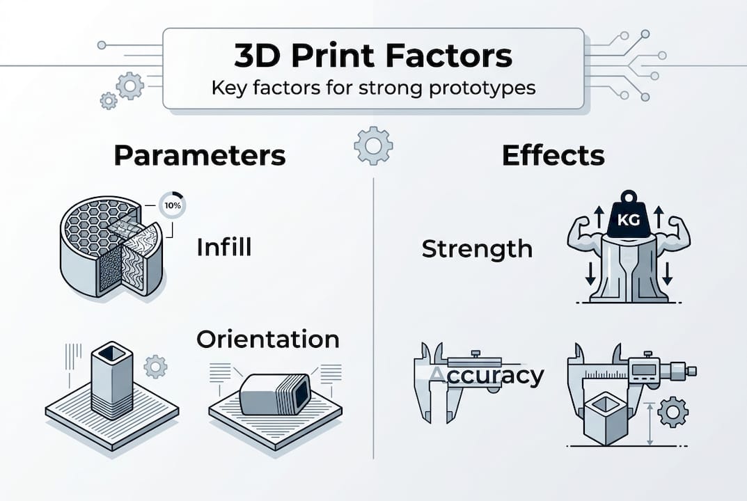
Repeatability is where most teams underestimate the challenge. Even with the same file and the same machine, small process variations can produce inconsistent results. Infill density alone accounts for up to 25.66% of the contribution to mechanical strength, meaning a small setting change ripples through your entire batch.

Here’s a quick checklist to assess your project before you start:

  • Define your dimensional tolerances before selecting a process
  • Identify whether the part is functional, aesthetic, or both
  • Estimate your acceptable cost per unit at your target quantity
  • Confirm your lead time requirements against your service provider’s capacity
  • Decide whether surface finish matters for fit, function, or customer presentation

The most common mistake in low-volume manufacturing is treating it like a scaled-down version of mass production. It isn’t. It’s a different discipline with different tradeoffs, and the teams that recognize that early save significant time and money.

For a deeper look at how design choices affect outcomes, the guidance on reliable 3D print design covers the foundational decisions that set your project up for success from the start.

Optimize 3D printing process parameters

Once you know what matters most for your parts, the next step is tailoring your 3D printing parameters for maximum performance. This is where many teams leave significant quality on the table by using default settings.

For FDM printing with PLA, research-backed optimal FDM PLA settings point to a nozzle temperature of 210°C, print speed of 30mm/s, layer height of 0.1mm, and a 0° raster angle. These settings consistently produce parts with tensile strength of 51 MPa and a Young’s modulus of 3400 MPa. That’s not just a lab number. It translates directly to real-world part durability.

Hand adjusting FDM 3D printer nozzle detail

Here’s a quick parameter reference to guide your setup:

Parameter Recommended setting Impact
Nozzle temperature 210°C (PLA) Affects layer adhesion and flow
Print speed 30 mm/s Slower speeds improve bonding
Layer height 0.1 mm Finer layers increase precision
Raster angle Maximizes tensile strength
Infill density 20-50% (functional) Strongest predictor of strength

Part orientation is another variable that product developers often overlook. Printing a part flat versus upright changes where the layer lines run relative to the load direction. For parts that experience bending or tension, orienting the strongest axis along the load path can make a measurable difference in service life.

Pro Tip: Use conservative parameters (lower speed, higher infill) for end-use functional parts, and faster, lower-infill settings for early-stage appearance prototypes. This lets you move quickly on concept validation without burning material budget on parts that will change anyway.

For a full breakdown of how each variable interacts, the 3D printing parameter guide walks through the logic behind each setting in practical terms. If you’re still getting familiar with the vocabulary, the 3D printing terminology resource is a solid starting point before diving into parameter tuning.

Select the best 3D printing technology and materials

Optimizing your process only works if you start with the right technology and materials. The choice between FDM, SLA, and SLS isn’t just a cost question. (A note on scope: our own production at CC 3D Labs runs on a calibrated FDM print farm — we cover SLA and SLS here so you can compare processes, and if your part genuinely needs one of them, we’ll say so and point you to the right provider.) It shapes what your part can actually do.

SLS offers stronger mechanics for functional parts, while SLA excels in surface aesthetics and fine detail. FDM sits in the middle, offering the widest material range and lowest cost, but with visible layer lines and more post-processing for smooth finishes.

Here’s a side-by-side comparison to help you decide:

Technology Strength Surface finish Cost Best for
FDM Moderate Visible layers Low Functional prototypes, enclosures
SLA Moderate Excellent Medium Aesthetic models, dental, jewelry
SLS High Good Higher Functional end-use parts, complex geometry

Material selection matters just as much as technology. Here’s a quick breakdown:

  • PLA: Easy to print, good for visual prototypes, not ideal for heat or impact
  • PETG: Better chemical resistance and flexibility than PLA, great for functional parts
  • ABS: Strong and heat-resistant, but warps without enclosure control
  • Advanced polymers (Nylon, TPU, PC): For demanding functional applications requiring flexibility, high heat, or impact resistance

Matching your material to your application is non-negotiable. A housing that looks identical in PLA and PETG will behave very differently in a warm environment or under repeated stress. For a detailed comparison of how materials hold up under real conditions, the guide on material selection for durability is worth reviewing before you finalize your spec. If you’re still deciding between technologies, the printing technology comparison breaks down the tradeoffs in practical terms.

Streamline workflow for precision and fast turnaround

With your process and materials set, integrating smart workflow habits will unlock true low-volume agility. The gap between a smooth run and a frustrating one is usually in the steps before and after printing.

Here’s a proven workflow sequence for low-volume 3D printing runs:

  1. Design for manufacturing (DFM) review: Check wall thickness, overhangs, and feature sizes before sending any file. Catching a design issue at this stage costs nothing. Catching it after printing costs time and material.
  2. File preparation: Export in STL or STEP format. Check for non-manifold geometry and repair errors using slicer software before submission.
  3. Slicer review: Confirm support placement, layer orientation, and infill settings match your part’s functional requirements.
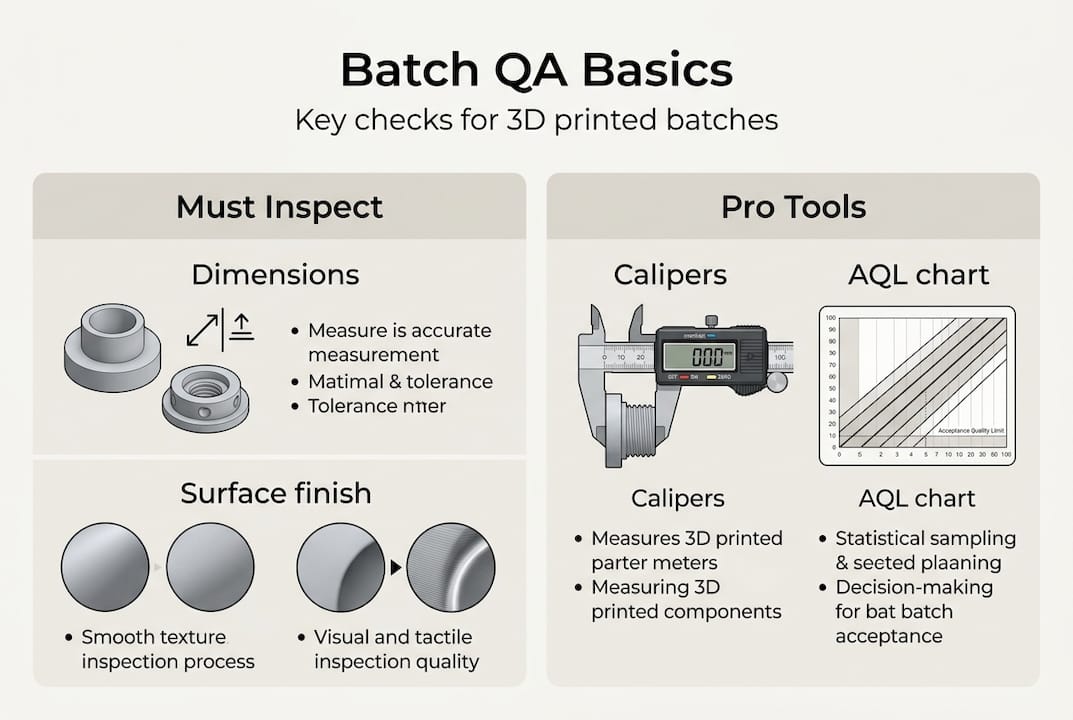
  4. First article inspection: Print one part first. Measure critical dimensions before committing to the full batch.
  5. Mid-run quality check: For batches above five parts, inspect a sample mid-run to catch any machine drift early.
  6. Post-processing review: Confirm that any sanding, priming, or hardware insertion meets spec before the parts ship or go to assembly.

Tuning every step of the process is what ensures repeatability and reliable part quality, especially at low volume where there’s no buffer for bad parts.

Pro Tip: Before your first production run with a new 3D printing partner, share your tolerance requirements and intended use case upfront. A good partner will flag potential issues before they become reprints. That conversation saves more time than any single parameter tweak.

For teams working with complex file structures or multiple CAD tools, the resource on CAD workflow optimization covers the file format decisions that affect print accuracy from the start.

Why precision matters more in low-volume manufacturing than you think

Here’s a perspective that doesn’t get enough airtime: low-volume manufacturing actually demands more process discipline than high-volume production, not less. That’s counterintuitive, but it’s true.

In mass production, variation averages out. You get thousands of data points, statistical process control kicks in, and outliers get caught before they reach customers. In a 10-part batch, one bad part is a 10% failure rate. Two bad parts and you’ve missed your delivery.

The conventional advice to “move fast and iterate” can backfire badly in this context. Skipping a first article inspection or using default slicer settings to save 20 minutes can produce a batch that fails dimensional checks entirely. The rework cost dwarfs the time saved.

Real-world functional parts require application-specific process control, not just impressive lab benchmarks. The teams that succeed in low-volume manufacturing treat each run with the same rigor they’d apply to a production line. They document settings, track results, and build a process knowledge base that makes every subsequent run faster and more reliable.

Working with a partner who applies that same discipline matters. The design discipline in prototype printing resource reflects exactly this mindset, where the goal is reliable outcomes, not just fast ones.

Take your low-volume manufacturing to the next level with CC3DLabs

Applying these strategies takes expertise, the right equipment, and a partner who treats your 10-part run with the same care as a 1,000-part order. That’s exactly what CC 3D Labs delivers.

https://cc3dlabs.com

Whether you need precision functional prototypes, small-batch production parts, or expert guidance on material and process selection, our 3D printing services are built for product developers who can’t afford to compromise on quality or speed. Explore 3D printing on demand for fast turnaround on custom parts, or see the range of prototypes to functional parts we produce for clients across industries. Request a free online estimate today and put these tips into practice with a team that knows exactly how to execute them.

Frequently asked questions

What is the ideal infill percentage for strong, low-volume 3D printed parts?

For most functional prototypes, an infill of 20-50% balances strength and material efficiency. Infill density is the single most critical parameter for tensile and compressive strength in FDM parts.

Which 3D printing method is best for functional, low-volume parts?

Selective Laser Sintering (SLS) is typically the strongest choice for functional, low-volume parts. SLS outperforms SLA on mechanical properties, while SLA leads on surface aesthetics.

Can adjusting print speed affect the durability of low-volume parts?

Yes, slower print speeds improve inter-layer bonding and increase overall part strength. 30mm/s print speed is the research-backed optimum for PLA FDM parts targeting maximum tensile performance.

What file format should I use for submitting 3D print jobs?

STL and STEP files are the preferred formats for most 3D printing workflows. They ensure broad compatibility with slicer software and preserve dimensional accuracy during file transfer.

Engineer preparing prototype for 3D scanning

3D Scanning Checklist: Ensure Accurate Prototypes & Parts


TL;DR:

  • Proper planning, environmental prep, and validation are essential to ensure accurate 3D scans.
  • Selecting the right scanner depends on part size, detail needed, and surface properties.
  • Rushing steps or skipping validation increases costly errors despite hardware quality.

One missed step in a 3D scanning workflow can send a prototype back to square one. For product developers and engineers, that means wasted hours, rework costs, and delayed production timelines. A structured checklist is not a bureaucratic formality; it is the difference between a scan you can trust and one that looks fine until the part fails tolerance checks on the shop floor. This guide walks through every critical phase: setting objectives, choosing the right scanner, preparing your environment, executing the scan, and validating results with objective metrics. Follow it consistently, and you will eliminate the most common sources of scanning error before they become expensive problems.

Table of Contents

Key Takeaways

Point Details
Define scanning requirements Clear goals and part specs are essential for selecting methods and validation metrics.
Match scanner to project Choose equipment based on part size and complexity for the highest accuracy.
Control prep and setup Careful part and environment preparation dramatically reduces errors and rescans.
Validate with metrics Use CF3D%, MD3D, and SQI3D to objectively confirm scan quality before moving to production.
Checklists prevent failures Following a robust checklist is more effective than relying solely on expensive scanners.

Set clear objectives and scan requirements

Every reliable 3D scan starts before you touch any hardware. The first step is defining exactly what you need the scan to accomplish, because that decision shapes every choice that follows.

Start by identifying the end use. A scan intended for a concept prototype has very different accuracy requirements than one destined for a production-ready part or a reverse-engineering workflow. Confusing these two contexts is one of the fastest ways to waste a scanning session.

Document the following before you begin:

  1. Part material and surface finish (matte, glossy, translucent, or metallic surfaces each require different handling)
  2. Overall dimensions and geometric complexity (simple prismatic parts versus freeform organic geometry)
  3. Required dimensional tolerance (what deviation is acceptable in millimeters or microns?)
  4. Downstream use (CAD comparison, mesh-to-print, inspection report, or reverse engineering)
  5. Deliverable format (STL, OBJ, STEP, or point cloud)

These five data points define your success criteria upfront. Without them, you are scanning blind.

Once you have your requirements documented, tie them to quantitative metrics. Quantitative metrics for 3D scanning research confirms you should always validate with Coverage Factor (CF3D%), Mean Distance (MD3D), and Scan Quality Index (SQI3D). CF3D% measures how much of the target surface your scan actually captured. MD3D quantifies the average deviation between your scan and the reference geometry. SQI3D combines multiple quality indicators into a single score for fast pass/fail decisions.

“Metric-based validation removes guesswork from the quality assessment process and creates a repeatable standard your entire team can apply.”

Setting these thresholds before the scan begins means you have an objective target to hit, not just a visual impression to judge. Understanding design accuracy and prototyping requirements is the foundation that makes every downstream decision faster and more defensible.

Pro Tip: Write your tolerance and metric thresholds directly on your scan request form. When multiple engineers are involved, this single habit eliminates the most common source of miscommunication between scanning and design teams.

Choose the right scanner and scanning method

With clear requirements in hand, the next step is selecting a scanner and scanning approach that fits those needs precisely. The wrong scanner type is not just a minor inconvenience; it can make it physically impossible to meet your documented tolerance requirements.

Here is a breakdown of the three most common scanner types used in engineering and product development:

  • Handheld laser scanners: Best for medium to large parts, complex assemblies, and on-site scanning. They offer flexibility and portability but typically deliver accuracy in the 0.05 to 0.1 mm range. Handheld laser scanners excel for prototypes up to 10 meters, while structured light scanners are the better choice for small, detailed parts.
  • Structured light scanners: Best for small to medium parts requiring high detail and tight tolerances. They project a pattern of light onto the surface and calculate geometry from the distortion. Accuracy can reach 0.01 mm or better, but they require a controlled environment and a stationary setup.
  • Photogrammetry: Best for very large objects or when portability is the priority. It uses overlapping photographs to reconstruct geometry. Accuracy is lower than laser or structured light methods, but it scales well and requires minimal equipment.

Matching the scanner to the part is not just about size. Consider these factors:

  • Surface reflectivity: Shiny or dark surfaces defeat most laser systems without preparation.
  • Feature size: Fine threads, sharp edges, or thin walls need structured light resolution.
  • Scan environment: Outdoor or production-floor scanning favors handheld systems.
  • Operator experience: Structured light systems have steeper learning curves.

Pro Tip: Do not let the scanner’s marketed accuracy spec be your only decision factor. Ask vendors for accuracy data on parts that match your geometry and surface type, not just flat reference artifacts.

If your project involves custom prototypes, understanding what makes the best print job for prototypes helps you align scanning precision with the print process you plan to use downstream. Similarly, reviewing how to choose the right printing type for production ensures your scan data will actually support the manufacturing method you intend to use.

Prepare the part and environment for scanning

Once you have the right scanner, expert results depend on methodical setup. This is the phase most engineers rush, and it is where most scan failures originate.

Follow this numbered preparation sequence every time:

  1. Clean the part thoroughly. Remove dust, oils, and loose debris. Even fine particles scatter laser light and introduce noise into the point cloud.
  2. Apply scanning spray if needed. Reflective, dark, or translucent surfaces require a temporary matte coating. Use a thin, even layer and allow it to dry completely.
  3. Secure the part with fixtures. Movement during scanning is the single biggest source of data misalignment. Use a turntable, magnetic fixture, or custom jig appropriate for the part geometry.
  4. Calibrate the scanner. Run the manufacturer’s calibration routine before every session, not just at the start of the day. Temperature changes affect optics.
  5. Set reference targets if required. Adhesive targets help the scanner track position across multiple scan passes on complex geometry.

Surface preparation and stable positioning are vital for reliable scans, and skipping either step creates problems that no amount of post-processing can fully correct.

Beyond the part itself, check these environmental factors:

  • Vibration: Isolate the scanning area from foot traffic, HVAC equipment, and nearby machinery.
  • Ambient light: Structured light scanners are sensitive to sunlight and fluorescent flicker. Use blackout curtains or scan in a dedicated room.
  • Background contrast: Place a neutral, non-reflective background behind the part to prevent the scanner from picking up stray geometry.
  • Temperature stability: Thermal expansion affects both the part and the scanner optics. Allow both to acclimate to room temperature before starting.

For a detailed look at what a controlled scanning environment looks like in practice, review our high quality 3D scan process guide. You can also explore our 3D Scanning Lab process or submit a 3D Scan Request Form to get professional support on your next project.

Technician prepping part in scanning room

Scan execution: capturing, validating, and optimizing data

With preparation complete, conducting the scan itself and validating results is where the checklist really proves its value. A clean setup does not guarantee a clean scan; you need a disciplined execution sequence.

Follow these steps in order:

  • Run an initial scan pass and review the raw mesh immediately. Do not wait until the end of the session to discover a problem area.
  • Check coverage visually and by CF3D% threshold. Any region below your target coverage percentage needs a re-scan pass before you move the part.
  • Identify and re-scan problem areas: undercuts, deep pockets, and thin walls are the most common trouble zones.
  • Align multiple scan passes using reference targets or software registration. Check alignment error before merging.
  • Export the validated mesh in the format your downstream workflow requires.

Here is a quick reference for the most common scan errors and how to address them:

Scan error Validation metric Corrective action
Missing surface coverage CF3D% below threshold Add scan passes from new angles
High deviation from reference MD3D exceeds tolerance Re-calibrate scanner, re-scan
Low overall quality score SQI3D fails Review all prep steps, repeat session
Mesh noise or spikes Visual + MD3D Reapply scanning spray, reduce ambient light
Misaligned scan passes MD3D between passes Re-register using reference targets

Validation metrics like CF3D%, MD3D, and SQI3D are essential for trustworthy scans, and applying them at each stage rather than only at the end catches errors while correction is still fast and cheap.

“A scan that passes visual inspection but fails metric validation is not a scan you can build a production part from.”

For export, use formats your CAD and manufacturing tools handle natively. Learning how to optimize workflow with CAD file formats prevents conversion errors that degrade scan accuracy. If you are newer to the terminology around scan outputs, the printing terminology for product developers guide clarifies common file type distinctions. For specialized applications like dental scanning standards, metric validation follows the same core principles but with even tighter tolerances.

Why most 3D scanning projects fail: The hidden checklist gaps

After working through hundreds of scanning projects, the pattern is clear: most failures are not hardware failures. They are process failures. The scanner was adequate. The operator was experienced. But someone skipped a step.

The three most common hidden gaps are rushing the setup phase, skipping metric validation in favor of visual approval, and assuming the scanner is inherently accurate enough without confirming it against your specific part geometry. Each of these feels like a time-saving shortcut in the moment and becomes a costly rework cycle later.

Skipped validation is a leading source of downstream part defects, and it is almost always avoidable. A five-minute metric check at the end of a scan session is far cheaper than discovering dimensional errors after a part has been printed or machined.

The uncomfortable truth is that a disciplined checklist on a mid-range scanner outperforms an ad-hoc process on a top-tier system every time. Hardware does not compensate for skipped steps. If you want to build a scanning workflow your team can trust, start with achieving high quality scans as your process baseline, then layer in metric validation as a non-negotiable exit criterion for every session.

Ready to streamline your 3D scanning workflow?

If your team is ready to move from ad-hoc scanning to a repeatable, validated process, CC 3D Labs is set up to support exactly that. We offer professional handheld 3D scanning (accuracy to ~0.1 mm), full prototyping, and expert guidance for product developers and engineers who need results they can build on.

https://cc3dlabs.com

Explore our 3D Scanning Lab services to see how we handle complex parts and tight tolerances. If your project needs both scanning and production, our full 3D printing services keep everything under one roof. And if you want to go deeper on best practices before you start, our high quality scan guide is the right next read. Get a free estimate and let us help you get it right the first time.

Frequently asked questions

What are the most important metrics for validating a 3D scan?

The key metrics are Coverage Factor (CF3D%), Mean Distance (MD3D), and Scan Quality Index (SQI3D). These three validation metrics quantify how complete and accurate your scan data is, giving you an objective pass/fail standard.

How do you select the right scanner for a specific part?

Base your choice on part size and required detail level. Scanner selection should match part size and complexity, with handheld lasers for larger prototypes, structured light for small intricate parts, and always confirm results with metric validation.

Why is environmental preparation important for 3D scanning?

Unstable or contaminated environments introduce noise, reflections, and misalignment errors that degrade scan accuracy. Surface and environmental prep is crucial for correct scans, and no post-processing step can fully recover data lost to a poor setup.

What mistakes commonly lead to poor scan quality?

Skipping preparation or validation reduces scan quality more than any hardware limitation. Using a mismatched scanner type for the part geometry is the third most frequent cause of rework.

How can engineers streamline 3D scanning workflows?

Standardize your setup sequence, define metric thresholds before each session, and treat the checklist as a non-negotiable process step. Detailed checklists and metric validation streamline workflows by catching errors early, when correction is fast and inexpensive.