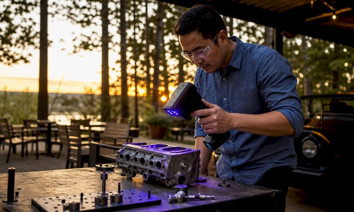
Engineer scanning a legacy car part with 3D scanner

Scanning for Legacy Part Reproduction: A 2026 Guide


TL;DR:

  • D scanning transforms physical legacy parts into detailed digital models for reproduction and inspection. It uses various methods, including structured light, laser, photogrammetry, and CT scanning, depending on the required accuracy and internal complexity. Proper workflow integration and documentation are essential to qualify reproduced parts in regulated industries and maximize the value of scan data.

3D scanning is the foundational step in legacy part reproduction, converting physical components into accurate digital models that engineers can inspect, modify, and manufacture from. The process, formally called reverse engineering through digitization, captures geometry down to fractions of a millimeter. This makes it possible to reproduce parts that have no surviving drawings, no original CAD files, and no active supplier. The role of scanning in legacy part reproduction goes beyond simple copying. It creates a verified digital record that supports future redesign, quality inspection, and regulatory traceability.

What scanning technologies are used in legacy part reproduction?

Four primary technologies drive 3D scanning in reproduction workflows: structured light scanning, laser scanning, photogrammetry, and industrial Computed Tomography (CT) scanning. Each method captures different types of geometry with different levels of accuracy and cost.

Structured light scanners project a grid pattern onto a surface and measure how the pattern deforms. This method captures external geometry with high resolution and works well for machined metal parts, housings, and connectors. Laser scanning uses a similar principle but projects a laser line instead of a grid, making it effective for larger parts and freeform surfaces.

High-resolution photogrammetry offers non-invasive, accurate 3D documentation that preserves surface details with minimal human intervention. It works by processing overlapping photographs through algorithmic pipelines. Photogrammetry is best suited for capturing texture and surface character rather than tight mechanical tolerances.

Industrial CT scanning stands apart from the other three methods. CT scanning generates non-destructive 3D volumetric models that reveal internal features, hidden cavities, and wall thicknesses without disassembling or damaging the original part. This makes CT the only viable option when internal geometry drives the function of the component.

Technology Best for Accuracy Key limitation
Structured light External surfaces, small parts Very high Limited to line of sight
Laser scanning Large parts, freeform surfaces High Surface reflectivity issues
Photogrammetry Texture, surface character Moderate Lower dimensional accuracy
Industrial CT Internal features, assemblies Very high High cost, slow throughput

Pro Tip: For parts with both complex external geometry and critical internal channels, combine structured light scanning for the exterior with CT scanning for internal features. This gives you a complete digital model without destroying the original part.
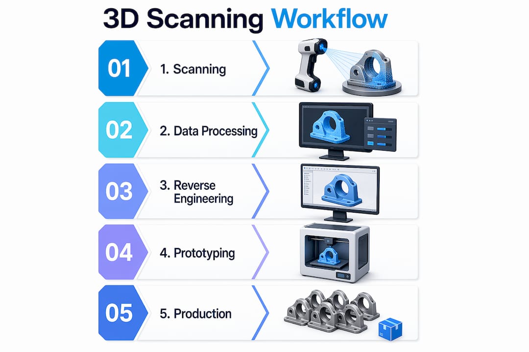
Infographic illustrating 3D scanning process steps

How does scanning integrate into the reverse engineering workflow?

Scanning is one step inside a larger reverse engineering process. Getting that step right requires a structured approach from the moment the physical part arrives.

  1. Initial assessment. Examine the part for damage, wear, and surface condition. Identify which features are functional and which are cosmetic. This determines which scanning method to use and where to focus resolution.
  2. Scan execution. Set up the scanner according to part size, material reflectivity, and required accuracy. For shiny metal surfaces, apply a temporary matte spray to reduce noise. Capture multiple passes to cover all angles.
  3. Data processing. Raw scan data often contains noise and incomplete surfaces. Dedicated software such as Geomagic Design X or Artec Studio processes the point cloud into a clean mesh. Skilled operators are required at this stage. Version control of scan files starts here.
  4. CAD reconstruction. Convert the mesh into a parametric CAD model using tools like SolidWorks or CATIA. This step requires engineering judgment, not just geometry tracing. The engineer must decide which features are nominal and which reflect wear or damage.
  5. Validation. Compare the reconstructed CAD model against the original scan data. Deviation maps highlight where the model diverges from the physical part. Acceptable tolerances depend on the application.

Pro Tip: Document engineering intent at every step. Note why a feature was modeled a certain way, especially when the physical part shows wear. That reasoning becomes part of the evidence chain needed for qualification in regulated industries.

Establishing a traceable qualification workflow that links part assessment, material identification, and scan data version control is the defining challenge in regulated sectors. Aerospace, defense, and medical manufacturers cannot simply reproduce geometry. They must prove the reproduction meets the original performance standard.

What are the benefits and challenges of 3D scanning for legacy parts?

The benefits of part scanning are concrete and measurable. professional handheld 3D scanning (accuracy to ~0.1 mm) captures accurate, watertight geometry,, capturing fine surface details and complex mechanical interfaces that manual measurement cannot reliably document. That level of accuracy eliminates the guesswork that comes with calipers and hand sketches.

Key benefits include:

  • Geometry capture without contact. Scanning preserves fragile or worn parts during the documentation process.
  • Speed. A structured light scanner can capture a full part surface in minutes. Manual measurement of the same part could take hours.
  • Complex feature documentation. Freeform surfaces, compound curves, and organic shapes that are impossible to measure manually are captured completely.
  • Digital twin creation. The scan becomes a permanent digital record for future inspection, redesign, or reproduction.

The challenges are equally real. Many reverse engineering projects stall because teams treat the work as a scanning task rather than a full data, compliance, and workflow integration effort. Geometry capture is necessary but not sufficient.

Specific challenges engineers face:

  • Data volume. High-resolution scans generate large point cloud files that require significant computing resources and organized storage.
  • Engineering intent. A scan captures what the part looks like now, not what it was designed to be. Worn features, corrosion, and deformation all appear in the scan data.
  • Material validation. Additive manufacturing material behavior differs from original manufacturing methods. Geometry matching alone does not qualify a reproduced part for service.
  • Audit trails. Regulated industries require documented evidence chains linking every decision from scan to final part.

Pro Tip: Build your evidence chain from day one. Log the scan date, operator, equipment calibration record, software version, and every processing decision. Retrofitting this documentation after the fact is expensive and often incomplete.

How do manufacturers apply scanning in practical production workflows?

The practical applications of digitization for legacy parts extend well beyond creating a one-time reproduction. Manufacturers use scan data across multiple production and maintenance scenarios.
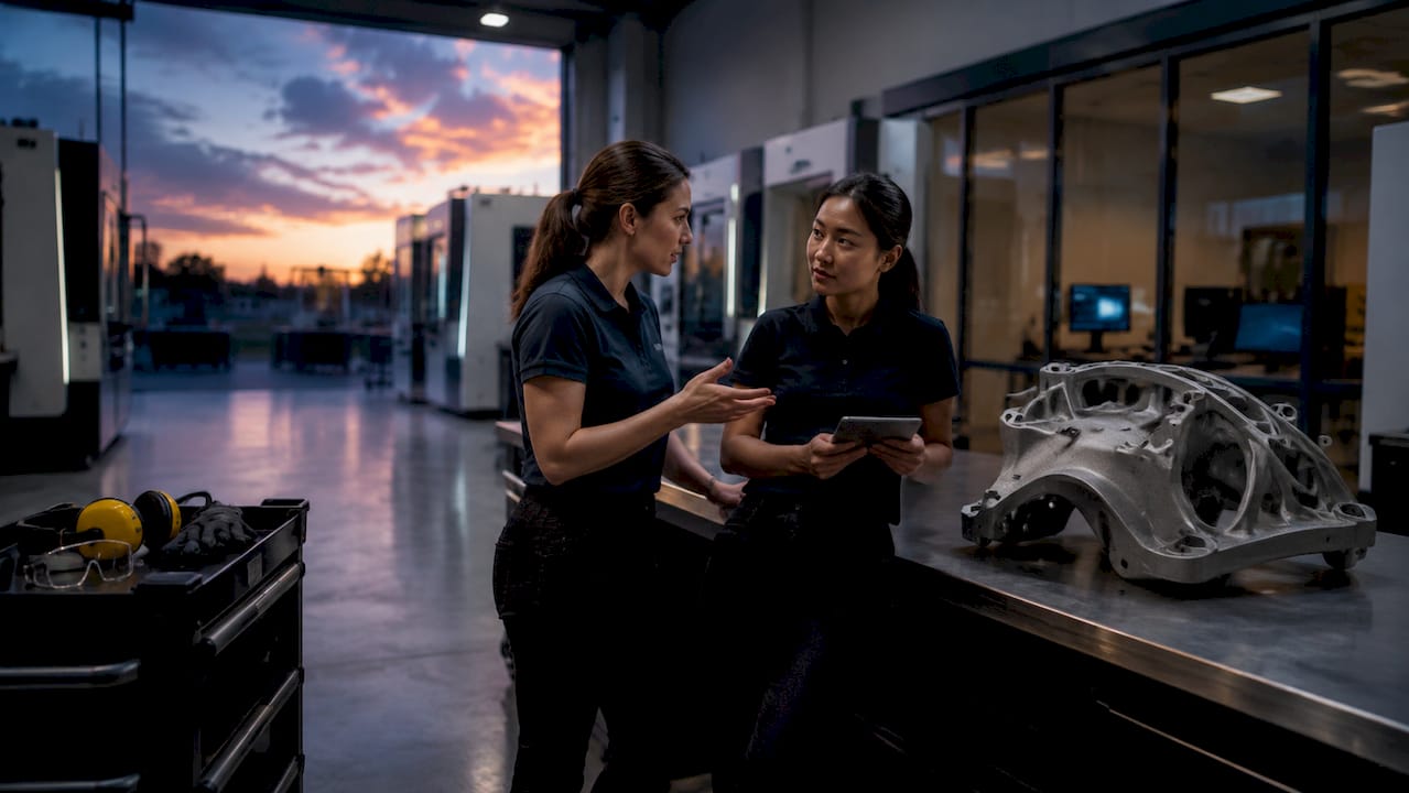
Technicians discussing 3D printed spare part on factory floor

High-fidelity scanning combined with additive manufacturing connects classical part geometry with modern digital production methods. A scanned digital twin can feed directly into a 3D printer for rapid prototyping, or into a CNC machining center for subtractive production. The same scan data supports both paths, which reduces lead time when a manufacturer needs to evaluate multiple production options quickly.

You can also use scan-derived digital twins for design accuracy and prototyping improvements. Engineers overlay the scan of a worn part against the original CAD model to measure how the part has changed in service. This data informs redesign decisions and helps predict future failure modes.

Application Scanning input Outcome
Spare part reproduction Full surface scan Replacement part manufactured to original geometry
Wear analysis Scan vs. nominal CAD Quantified deviation map for maintenance planning
Rapid prototyping Scan to mesh to print Physical prototype in hours for fit and function testing
Aftermarket servicing Scan of discontinued part New supplier tooling created without original drawings
Quality inspection Scan of produced part Automated comparison against design intent

Aftermarket and legacy vehicle servicing represent one of the highest-value applications. When a manufacturer discontinues a component and the original tooling no longer exists, a high quality 3D scan of a surviving example becomes the only path to reproduction. This is common in aerospace MRO (maintenance, repair, and overhaul), classic vehicle restoration, and industrial equipment servicing.

The production efficiency gains are direct. Eliminating manual measurement and manual redrawing removes two of the most error-prone steps in legacy part reproduction. Scan data feeds manufacturing equipment directly, which reduces the number of iterations needed to achieve a conforming part.

Key Takeaways

Scanning is the critical first step in legacy part reproduction, but traceable workflow integration, material validation, and engineering documentation determine whether a reproduced part qualifies for service.

Point Details
Scanning precision matters professional handheld scanners capture geometry to roughly 0.05–0.1 mm (50–100 microns), far beyond manual measurement capability.
Technology selection is part-specific CT scanning is required for internal features; structured light works best for external surfaces.
Workflow integration is non-negotiable Reverse engineering projects fail when teams treat scanning as the only task rather than one step in a documented process.
Material validation is separate from geometry A geometrically accurate scan does not automatically qualify a reproduced part, especially in regulated industries.
Digital twins extend value beyond reproduction Scan data supports wear analysis, quality inspection, and future redesign, not just one-time part replication.

Why scanning alone will not save your legacy part program

Most manufacturers I work with come to scanning with the right instinct but the wrong expectation. They assume that once the scan is done, the hard part is over. The opposite is true.

The scan gives you geometry. What it does not give you is engineering intent, material specification, or a qualification record. A worn part scanned at high accuracy still gives you a worn part. The engineer has to decide which dimensions represent the design and which represent 40 years of service. That judgment call is not in the scan file.

The manufacturers who succeed with legacy reproduction treat the scan as the beginning of a documented evidence chain, not the end of a measurement task. They track every decision, every software version, and every material substitution. In aerospace and defense, that chain is what gets a part approved. In commercial manufacturing, it is what prevents a costly recall.

The shift I see in 2026 is toward combined workflows where scanning, CAD reconstruction, additive manufacturing, and inspection all share the same data thread. Tools like Authentise and similar manufacturing execution platforms are making this more accessible. But the discipline of documentation still comes from the engineering team, not the software. If you are starting a legacy part program, build the process before you buy the scanner.

— Justin

Cc3dlabs scanning and reproduction services for legacy parts

Cc3dlabs operates a professional 3D scanning lab near Philadelphia that supports manufacturers, engineers, and product developers with professional handheld 3D scanning (accuracy to ~0.1 mm) and scan-to-CAD processing. The team handles structured light scanning for external geometry and works with clients on full reverse engineering workflows from initial scan through digital twin creation.

https://cc3dlabs.com

For manufacturers who need to move from scan data to physical parts, Cc3dlabs connects scanning directly to 3D printing and production services that support both rapid prototyping and functional part reproduction. Whether you need a single replacement component or a documented reproduction workflow for a regulated application, Cc3dlabs provides the precision and traceability support the job requires. Request a free online estimate to get started.

FAQ

What is the role of scanning in legacy part reproduction?

3D scanning converts a physical legacy part into an accurate digital model that engineers can use to reproduce, inspect, or redesign the component. It is the foundational step in reverse engineering when no original drawings or CAD files exist.

Which scanning method is best for internal part features?

Industrial CT scanning is the correct method for internal features. It generates non-destructive 3D volumetric models of hidden cavities, wall thicknesses, and internal assemblies without altering the original part.

Does scanning alone qualify a part for reproduction in regulated industries?

Scanning alone does not qualify a part. Regulated industries require a traceable qualification workflow that documents part assessment, material identification, scan data version control, and material validation alongside the geometric scan data.

How accurate is professional handheld 3D scanning (accuracy to ~0.1 mm)?

professional handheld 3D scanning (accuracy to ~0.1 mm) captures accurate, watertight geometry,. That level of accuracy captures fine mechanical interfaces and complex surface details that manual measurement methods cannot reliably document.

What software is used to process raw scan data into CAD models?

Tools like Geomagic Design X and Artec Studio process raw point cloud data into clean meshes. Engineers then use parametric CAD platforms such as SolidWorks or CATIA to reconstruct manufacturable models from the processed scan data.
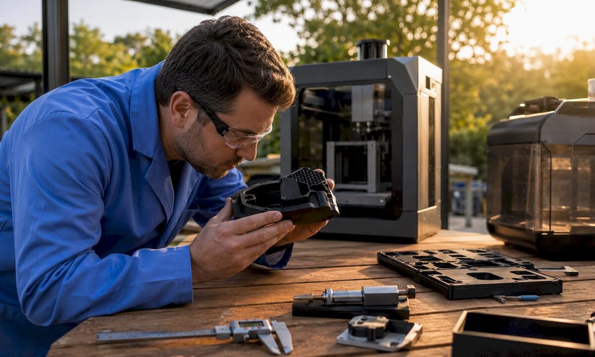
Engineer inspecting 3D printed part surface finish

The Role of Surface Finish in 3D Printing for Manufacturers


TL;DR:

  • Surface finish in 3D printing determines the texture, performance, and longevity of printed parts, requiring early specification. Different technologies like FDM, SLA, SLS, and metal fusion produce distinct Ra ranges, influencing post-processing needs. Proper design orientation, material choice, and targeted post-processing ensure optimal functional and aesthetic outcomes.

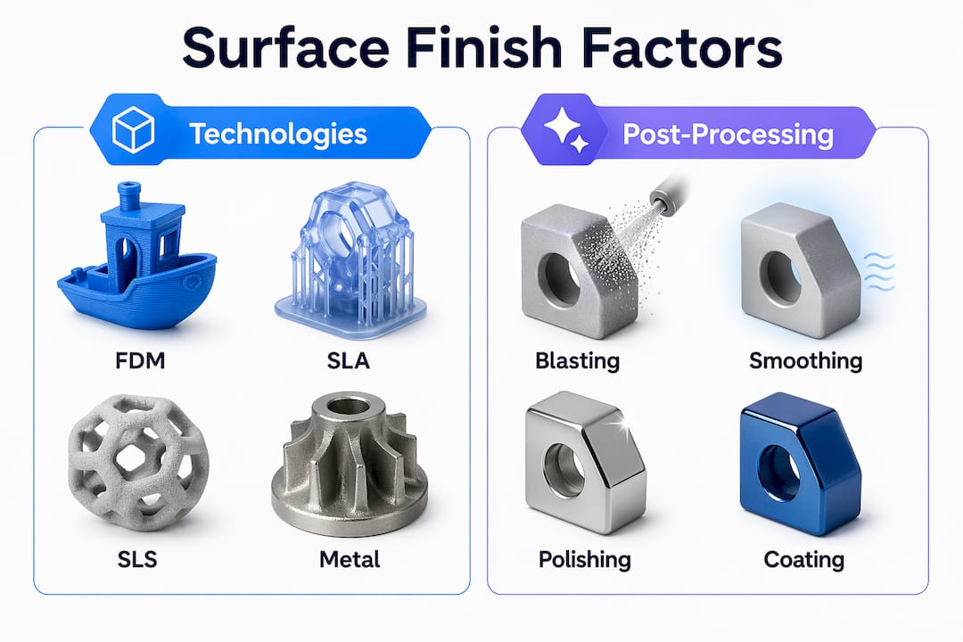
Surface finish in 3D printing is defined as the measurable texture and topography of a printed part’s outer layer, and it directly determines whether that part succeeds or fails in its intended application. The role of surface finish in 3D printing extends far beyond appearance. It governs fit, friction, fatigue life, sealing performance, and fluid dynamics. Manufacturers working with FDM, SLA, SLS, or metal powder bed fusion processes each encounter distinct surface characteristics tied to their technology. Surface quality is quantified using roughness average (Ra), measured in micrometers, and this single metric carries significant weight in aerospace, medical, and industrial component qualification. This article covers how printing technology, post-processing, and design decisions each shape the final surface outcome.

How do different 3D printing technologies influence surface finish?

Every additive manufacturing process produces a characteristic surface texture, and understanding those defaults is the starting point for any finish specification. The root cause of most surface imperfections is the layer-by-layer build process, which creates a staircase effect on curved and angled surfaces. The severity of that staircase depends on layer height, material behavior, and process physics.

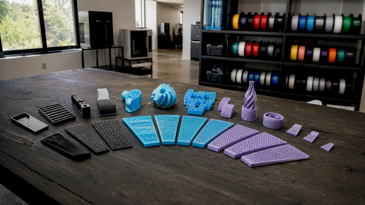
Different 3D printed surface textures on desktop

FDM (Fused Deposition Modeling) produces the most visible layer lines of any common process. Typical Ra values for FDM parts range from 10 to 30 μm, depending on layer height and material. PLA and ABS parts printed at 0.2 mm layer height show clear bead extrusion ridges that require sanding or chemical smoothing before use in consumer-facing applications.

SLA (Stereolithography) uses a UV laser to cure liquid resin, producing surfaces with Ra values as low as 1 to 3 μm right off the printer. The result is a near-glassy finish that requires minimal post-processing for aesthetic parts. However, support attachment points leave small scars that must be addressed before final use.

SLS (Selective Laser Sintering) fuses nylon powder, leaving a grainy, matte texture with Ra values typically between 6 and 12 μm. The surface has a sandpaper-like quality that works well for functional prototypes but needs bead blasting or dyeing for production parts.

Metal powder bed fusion processes, including DMLS and SLM, produce surfaces with Ra values ranging from 6 to 20 μm. Residual powder particles fused to the surface and layer lines both contribute to roughness. Post-machining or electropolishing is standard for sealing surfaces and bearing interfaces.

Technology Typical Ra Range Primary Surface Issue
FDM 10–30 μm Visible layer lines, bead ridges
SLA 1–3 μm Support scars, resin blush
SLS 6–12 μm Grainy powder texture
Metal DMLS/SLM 6–20 μm Fused powder, staircase effect
Material Jetting 1–4 μm Waxy surface, UV sensitivity

Infographic comparing 3D printing technologies and post-processing methods affecting surface finish

Print orientation compounds these effects. Surfaces printed at shallow angles relative to the build plate show the most pronounced staircase stepping. Vertical walls on FDM parts are smoother than 45-degree overhangs because the layer transitions are less visible. Surface finish in additive manufacturing is a critical functional parameter that affects fit, fluid dynamics, wear resistance, and fatigue life across all of these technologies.

What post-processing techniques enhance surface finish?

Post-processing is where manufacturers close the gap between as-printed texture and production-grade quality. The right method depends on material, geometry, required Ra value, and whether the part needs dimensional stability after finishing.

Media blasting and bead blasting are the most common first steps for SLS and metal parts. Blasting removes loose powder, smooths texture, and creates a uniform matte finish. It does not significantly alter dimensions, making it safe for tight-tolerance features. Media blasting and chemical smoothing effectively eliminate stair-stepping effects inherent to layered printing.

Chemical vapor smoothing works by exposing a part to solvent vapor that melts and redistributes the outermost surface layer. For FDM ABS parts, acetone vapor smoothing can reduce Ra from 20 μm down to 2 to 4 μm in minutes. The trade-off is slight dimensional change and the need for controlled ventilation. For nylon SLS parts, dedicated vapor smoothing systems like AMT PostPro3D achieve similar results with better repeatability.

Tumbling and vibratory finishing use abrasive media in a rotating drum to smooth small parts uniformly. This method works well for batches of small, geometrically simple parts but is size-limited and can round sharp edges that are functionally important.

Sanding and polishing remain the most controllable methods for achieving very low Ra values on accessible surfaces. Progressive grits from 120 to 2000, followed by polishing compound, can bring SLA or FDM parts to a mirror finish below 0.5 μm. The limitation is labor cost and the inability to reach internal channels or complex geometry.

Painting and dyeing add color and a protective layer simultaneously. Dyeing is particularly effective for SLS nylon, penetrating the surface rather than coating it, which preserves dimensional accuracy. Painting adds thickness, typically 50 to 100 μm per coat, which must be accounted for on mating surfaces.

Method Best For Ra Improvement Key Trade-off
Bead blasting SLS, metal Moderate Matte only, no gloss
Vapor smoothing FDM ABS, nylon High Slight dimensional change
Tumbling Small batch parts Moderate Size and geometry limited
Sanding/polishing Accessible surfaces Very high Labor intensive
Painting/dyeing Aesthetics, protection Low (coating) Adds thickness

Pro Tip: Specify your required Ra value before selecting a post-processing method. Working backward from the functional requirement, such as Ra 0.8 μm for a sealing surface, prevents over-processing and unnecessary cost. Learn more about the full spectrum of options in this 3D print finishes guide.

How does surface finish affect functional performance?

Surface roughness is an engineering variable with direct consequences for part performance. Mismanaging surface finish causes technical failures including leaking gaskets, seized parts, and premature fatigue because surface anomalies initiate stress cracks. This is not a cosmetic concern. It is a structural one.

The fatigue life relationship is quantitative. Reducing surface roughness from Ra 3.2 μm to 0.8 μm in metal parts produces fatigue strength improvements of 15 to 30%. For a load-bearing bracket or a cyclic-stress component in a medical device, that improvement can be the difference between a 10-year service life and a premature failure.

Friction and wear behavior depend on surface texture in ways that are not always intuitive. Rough surfaces create higher initial friction and accelerate wear in sliding contact. However, some applications require specific surface textures to retain lubricants, and over-finishing can starve mechanical assemblies of necessary lubrication. A bearing journal polished to Ra 0.1 μm may actually perform worse than one finished to Ra 0.4 μm because the lubricant film cannot be maintained.

Sealing performance adds another layer of complexity. Both too rough and too smooth surfaces can cause leaks or micro-leaks in gasket interfaces. A controlled Ra value, typically between 1.6 and 3.2 μm for most elastomeric gaskets, creates enough texture for the gasket to conform without allowing leak paths through deep valleys.

Fluid dynamics in internal channels are also affected. Rough internal surfaces in printed manifolds or heat exchangers increase turbulent flow and pressure drop. For high-flow hydraulic components, this translates directly to energy loss and heat generation. Electropolishing or abrasive flow machining of internal channels is standard practice in precision fluid systems.

Dimensional accuracy at assembly depends on finish as well. A shaft printed to nominal diameter with Ra 15 μm will measure differently than one finished to Ra 1.6 μm because the roughness peaks add effective material. Understanding this relationship is covered in detail in precision 3D part qualities that every engineer should account for at the design stage.

What design decisions optimize surface finish from the start?

The most cost-effective surface finish strategy begins in CAD, not at the finishing bench. Surface finish is a decisive factor in lifecycle costs and reliability, and decisions made during design and print setup determine how much post-processing will be required.

  1. Orient critical surfaces away from support contact. Support structure removal causes surface scarring that compromises dimensional accuracy if not accounted for at the design stage. Placing cosmetic or functional surfaces on self-supporting faces eliminates this problem entirely.

  2. Rotate parts to minimize staircase effects on key features. Rotating parts by 45 or 90 degrees optimizes surface finish on sloped features and reduces post-processing time and cost. A cylindrical bore printed vertically will have a smoother inner wall than one printed horizontally.

  3. Reduce layer height on finish-critical parts. Dropping from 0.2 mm to 0.1 mm layer height on an FDM part roughly halves the visible staircase amplitude. Print time increases, but post-processing time decreases, and the net cost is often lower for small-batch production.

  4. Specify Ra requirements on your drawing before quoting. Suppliers cannot hit a target they have not been given. Defining Ra values for sealing surfaces, bearing interfaces, and cosmetic faces at the RFQ stage prevents mismatched expectations and rework.

  5. Account for finishing stock in your CAD model. If a surface will be sanded or machined after printing, add 0.3 to 0.5 mm of material to that face. This preserves final dimensions after material removal.

Pro Tip: For manufacturing-grade 3D printed parts, treat surface finish as a design input, not an afterthought. Document finish requirements in your technical drawing the same way you would a tolerance or material callout.

Support structure scarring is a major contributor to surface defects, and anticipating this during CAD design reduces costly rework and maintains accuracy. The best manufacturers build finish considerations into their design review checklist, not their inspection report.

Key takeaways

Surface finish in 3D printing is a functional engineering parameter that must be specified, designed for, and controlled from the first CAD decision to the final post-processing step.

Point Details
Technology sets the baseline FDM, SLA, SLS, and metal processes each produce distinct Ra ranges that define your starting point.
Post-processing closes the gap Methods like vapor smoothing, bead blasting, and polishing can reduce Ra by an order of magnitude.
Finish drives functional outcomes A 15 to 30% fatigue strength gain is achievable by reducing Ra from 3.2 μm to 0.8 μm in metal parts.
Over-finishing carries real risk Surfaces polished below optimal Ra can fail to retain lubricant, causing premature wear in assemblies.
Design orientation is the cheapest fix Rotating a part 45 to 90 degrees during setup reduces staircase effects without adding cost.

Surface finish is the variable most manufacturers underestimate

I have reviewed hundreds of part drawings from product developers who specify tight dimensional tolerances down to 0.05 mm but leave the surface finish field blank. That blank field is where failures are born. A gasket surface with Ra 12 μm will leak under pressure cycling regardless of how accurate the bore diameter is. A sliding shaft with Ra 25 μm will wear its mating bore in weeks, not years.

The misconception I encounter most often is that surface finish is a cosmetic concern addressed at the end of the process. The reality is the opposite. Finish requirements should appear on the drawing before the first print parameter is set. The technology choice, orientation, layer height, and post-processing sequence all flow from that specification.

What I find genuinely encouraging is how much the as-printed baseline has improved. 3DEO’s Intelligent Layering technology produces production-grade metal parts with smooth surfaces and tight tolerances directly off the printer, which challenges the assumption that additive manufacturing always requires heavy post-processing. That capability is spreading across the industry. The gap between additive and machined surface quality is narrowing every year.

My practical advice: treat surface finish as a first-class design parameter. Write it on the drawing. Discuss it with your print supplier at the quoting stage. And if you are unsure what Ra value your application requires, look at the equivalent machined part specification and use that as your target. The post-processing methods available today can hit almost any target. The question is whether you have defined the target clearly enough to hit it.

— Justin

How Cc3dlabs helps manufacturers achieve production-grade surface finish

https://cc3dlabs.com

Cc3dlabs, based near Philadelphia, works with manufacturers and product developers who need more than a rough prototype. Their FDM printing capabilities cover a range of engineering-grade materials, and their post-processing options include sanding, painting, and finishing tailored to functional requirements. Every project starts with a design review that includes surface finish specification, so parts arrive ready for assembly, not for rework. For teams managing batch production or iterating on functional components, Cc3dlabs offers fast turnaround, free online estimates, and direct design support. Explore their full range of capabilities on the 3D printing services page and request a quote for your next production run.

FAQ

What is surface finish in 3D printing?

Surface finish in 3D printing refers to the texture and roughness of a part’s outer surface, measured as roughness average (Ra) in micrometers. It affects how a part looks, how it fits with mating components, and how it performs under mechanical stress or fluid pressure.

Which 3D printing process produces the smoothest surface?

SLA and material jetting produce the smoothest as-printed surfaces, with Ra values as low as 1 to 3 μm. FDM produces the roughest baseline finish, typically between 10 and 30 μm, and almost always requires post-processing for functional or cosmetic applications.

How does surface roughness affect fatigue life?

Reducing Ra from 3.2 μm to 0.8 μm in metal parts improves fatigue strength by 15 to 30%. Surface irregularities act as stress concentration points where fatigue cracks initiate, so smoother surfaces directly extend component service life.

Can over-polishing a 3D printed part cause problems?

Yes. Some mechanical assemblies require a specific surface texture to retain lubricant. Polishing a surface below the optimal Ra value can prevent lubricant film formation, leading to metal-to-metal contact and accelerated wear.

When should surface finish be specified in the design process?

Surface finish requirements should be specified on the technical drawing before the first print parameter is selected. Early specification allows the print supplier to choose the correct technology, orientation, and post-processing sequence to hit the target at the lowest cost.

Engineer reviewing 3D scan data in office

Why 3D Scan Data Integrity Is Crucial for Manufacturing


TL;DR:

  • High-resolution scans alone do not guarantee usable data, as accuracy, repeatability, and traceability are essential for reliable 3D imaging. Environmental conditions, operator technique, calibration, and software processing all threaten data integrity, which must be systematically protected through calibration, controlled environments, and documented workflows. Ensuring data integrity accelerates manufacturing, reduces errors, and improves project outcomes by providing dependable, traceable scan results.

High-resolution scans look impressive, but resolution alone does not determine whether your data is usable. Understanding why 3D scan data integrity is crucial separates professionals who consistently hit tolerances from those who keep chasing errors back to the source. Data integrity covers accuracy, repeatability, traceability, and processing quality. Miss any one of those, and even a visually detailed point cloud can collapse your prototyping workflow before a single part is printed or machined. This article explains what integrity actually means in a scanning context, what threatens it, and how to protect it at every stage of your workflow.

Table of Contents

Key Takeaways

Point Details
Resolution does not equal accuracy A high-resolution scan can still contain dimensional errors that ruin a prototype or manufactured part.
Integrity is a system-level property Hardware, software, operator technique, and environment must all work together to produce trustworthy data.
Calibration is non-negotiable Regular, traceable calibration prevents measurement drift and keeps scan data defensible for manufacturing acceptance.
Environment and operator matter as much as hardware Temperature gradients, vibration, and poor scanning technique introduce errors that even premium scanners cannot correct.
Reliable data accelerates the entire workflow Confident scan data reduces rework, speeds up iteration, and lowers the cost of production errors.

Why 3D scan data integrity is crucial: the core concepts

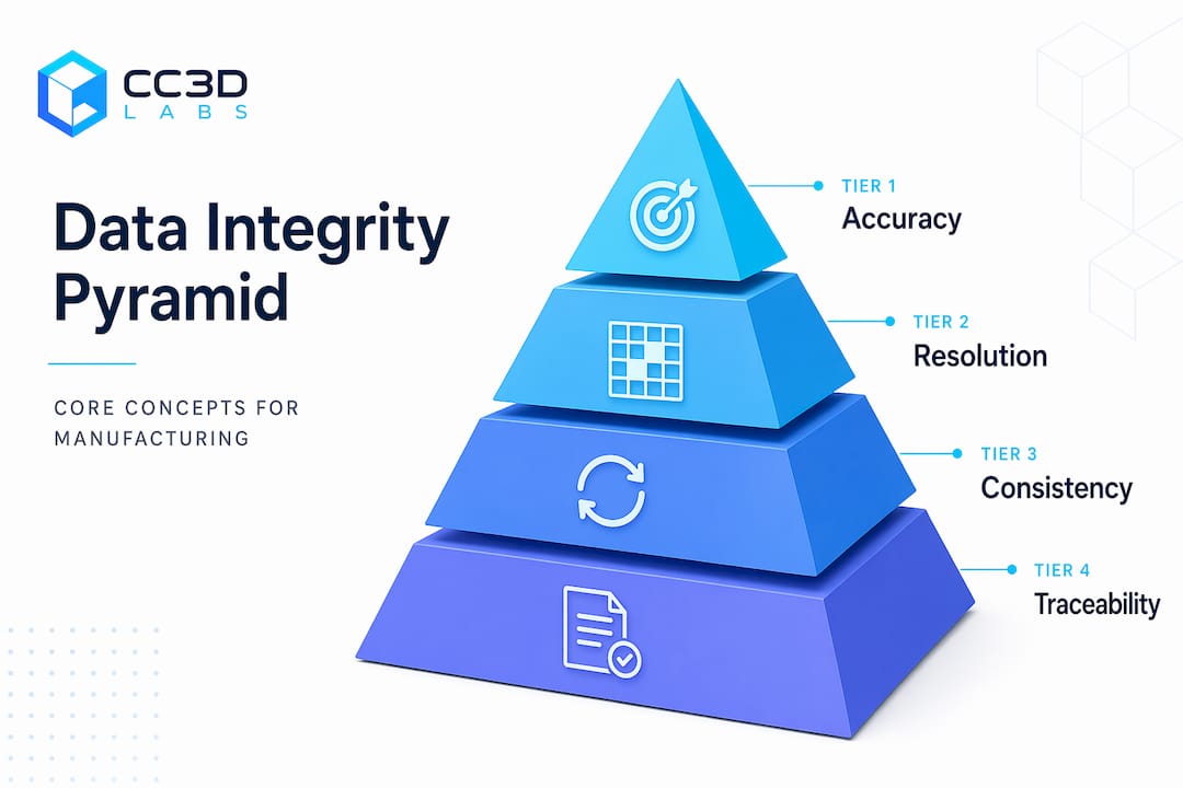
Before you can protect data integrity, you need a precise definition of what it includes. Four concepts form the foundation: accuracy, resolution, consistency, and traceability. Most professionals use the first two interchangeably, and that habit costs time and money.

Accuracy vs. resolution

Resolution and accuracy serve fundamentally different functions. Resolution describes how much surface detail the scanner captures. Accuracy describes how close those captured dimensions are to the physical truth of the object. A scanner can produce a beautifully detailed mesh at 0.05 mm point spacing that still carries a 0.3 mm dimensional error. In a product development workflow, the detail impresses stakeholders during review. The dimensional error shows up as a misfit during assembly.

High resolution also carries a practical cost. Excessive point density inflates file size, bogs down mesh repair, and slows every downstream process from CAD alignment to slicing. Matching resolution to intended use is not a compromise. It is the correct engineering decision.

Technician repairing scan mesh at lab bench

Consistency and traceability

Infographic pyramid showing scan data integrity concepts

Reliable scan data depends on repeatability, not just one good result. If scanning the same part twice under identical conditions produces meaningfully different outputs, nothing in your workflow is defensible. Consistency lets you trust comparisons, revisions, and inspection sign-offs.

Traceability ties your scan results to a verifiable standard. Calibrated reference artifacts, documented scan settings, and formal quality reports are what transform a point cloud from a visual deliverable into a manufacturing document. Consider the difference between a scan submitted to a contract manufacturer alongside a formal quality report that documents control points, outlier handling, and calibration history versus one submitted without any of that context. The first one gets approved. The second one gets questions.

  • Accuracy: Dimensional closeness to the physical object, measured against traceable standards
  • Resolution: Point density and surface detail, which should be matched to the specific use case
  • Consistency: Repeatability across sessions, operators, and equipment states
  • Traceability: Documentation linking scan results to calibrated standards and documented procedures

Together, these four elements define what strong 3D scanning data reliability actually looks like in practice.

Common threats to scan data integrity

Understanding the risks is not about pessimism. It is about knowing exactly where to focus your attention. Data integrity in 3D scanning is an emergent property, meaning it arises from multiple interacting layers rather than from any single component. When vulnerabilities in those layers align, even a capable scanner produces flawed data. This is the Swiss-cheese model applied to metrology workflows.

Here are the most common sources of failure, ranked by how often they are overlooked:

  1. Environmental conditions. Temperature, lighting, and vibration are the most underestimated threats to scan accuracy. Thermal expansion in a part being scanned in a warm production floor can shift dimensions measurably between the start and end of a single scan session. Air temperature gradients create measurement drift that no post-processing step can fully undo.

  2. Operator technique. The scanning path, standoff distance, overlap between passes, and handling of reflective or dark surfaces all introduce variability. Two operators scanning the same part with the same scanner can produce outputs that differ by more than the printed tolerance on the drawing.

  3. Hardware calibration drift. Sensors drift. Mechanical components develop play. A scanner that produced accurate results six months ago may no longer meet its stated specifications if calibration has not been maintained. This is particularly dangerous because the data often looks normal while carrying hidden dimensional errors.

  4. Software processing errors. Registration algorithms, mesh smoothing filters, and hole-filling routines all make decisions that affect dimensional truth. Default settings are not optimized for every geometry or material. Blindly applying them without understanding the tradeoffs is a common source of data degradation.

  5. Multiple interacting failures. The Swiss-cheese model predicts that single layers of defense rarely fail catastrophically on their own. An error in any one area is manageable. When poor environmental control, a drift-affected sensor, and aggressive mesh smoothing align in the same workflow, the result is data that looks clean but fails downstream.

Pro Tip: Before a major scan session, run a reference artifact through your full workflow, from capture to processed mesh. If the output falls outside your expected tolerance range, stop and find the cause before scanning the actual part.

Best practices to protect and maintain data quality

Knowing the threats is useful. Having a system to counter them is what actually protects your data. Reliability is a system-level outcome driven by calibration, environment, operator discipline, and software controls working together. No single action is enough on its own.

Calibration and traceable standards

Calibrate your scanner on a scheduled basis using certified reference artifacts. Document every calibration event with date, environmental conditions, and results. This documentation is what makes your data defensible for manufacturing acceptance in contract environments.

Modern high-accuracy scanners in 2026 can achieve volumetric accuracy of 0.03 mm + 0.05 mm per meter using multi-line laser modes, but that performance is only realized when calibration is current and conditions are controlled.

Hardware selection and environment control

Factor What to prioritize What to avoid
Scanner grade Metrology or industrial grade with stable housing Consumer devices for tight-tolerance work
Connectivity Onboard processing with dual Wi-Fi to prevent data loss Wireless setups that stream raw packets without error correction
Environment Temperature-controlled, vibration-dampened, diffuse lighting Bright window light, HVAC drafts, concrete floors near heavy machinery
Surface prep Matte reference spray or targets for reflective/dark surfaces Relying on raw surface appearance without preparation

Software and post-processing controls

Do not treat post-processing as cleanup. Every filter and alignment decision is a data modification. Use the minimum smoothing necessary for your application. Document the processing settings applied to each dataset. For high-quality manufacturing scans, the goal is mesh fidelity to the physical object, not visual appeal.

Pro Tip: Save both the raw point cloud and the processed mesh as separate files. If an alignment or filtering decision turns out to be wrong during CAD review, you can reprocess from raw data without rescanning the part.

  • Align scans using physical reference targets, not just software-generated feature matching
  • Run mesh quality checks before exporting, including hole counts, intersecting faces, and non-manifold edges
  • Match your export format and polygon count to what the downstream tool actually needs

The business impact of accurate scan data

The significance of 3D data integrity becomes clearest when you trace it directly to project outcomes. Reliable scan data reduces costly downstream failures and builds confidence in every decision that follows the scan. That effect compounds quickly in iterative product development.

Consider a typical reverse engineering project. A product team scans an existing component to create a replacement part. If the scan carries a 0.2 mm accuracy error and the designer does not detect it, the CAD model inherits that error. The prototype is printed or machined to that incorrect model. The fit test fails. The team scans again, remodels, reprints. Each cycle costs time and materials. The root cause was never the printing or machining. It was the scan data.

The importance of 3D scan accuracy is equally clear in inspection workflows. When scan data is traceable and consistent, it serves as a legal and contractual record of part geometry at a specific point in time. That record supports quality sign-offs, warranty claims, and deviation approvals with documented evidence rather than verbal assurance.

  • Accurate scan data cuts the number of prototype iterations by giving designers a reliable baseline to work from
  • Clean, well-structured mesh files reduce prep time in CAD and slicing software, directly lowering labor costs per part
  • Traceability documentation supports ISO and AS9100 quality requirements, which matter in aerospace, medical, and automotive supply chains
  • Consistent data across scan sessions makes it possible to detect genuine part wear or tooling drift, rather than noise from scan variability

For teams doing rapid prototyping, the benefits of accurate 3D scans are not abstract. They show up in the number of design cycles completed per week, the scrap rate on first-article inspection, and the speed of design sign-off. Those are the metrics that determine project profitability.

My take on where most teams go wrong

I have reviewed a lot of 3D scanning workflows over the years, and the pattern that frustrates me most is not carelessness. It is misplaced focus. Teams spend considerable money on a premium scanner and then operate it in conditions that undermine every advantage the hardware offers. The scanner becomes a status symbol rather than a calibrated instrument.

The misconception I run into most often is that a higher price tag or a more impressive spec sheet guarantees better data. It does not. A well-operated mid-range scanner in a controlled environment with a disciplined operator consistently outperforms a high-accuracy instrument scanned on a vibrating factory floor by someone who has not been trained on the specific geometry they are capturing.

What I have learned from working through enough failed prototypes is that workflow discipline matters more than any single tool upgrade. Calibration schedules, environmental logs, processing documentation, and reference artifacts are unglamorous. They do not appear in marketing materials. But they are the actual mechanism by which good data gets produced reliably, not occasionally.

My honest recommendation is to build your scanning protocol before you buy your next scanner. Understand exactly what the workflow demands in terms of accuracy, consistency, and traceability. Then select hardware that fits that protocol. The teams that do this consistently produce better outcomes than teams chasing the highest-spec device without a system around it.

— Justin

Get reliable scan data with Cc3dlabs

If this article has clarified what 3D scan data integrity actually requires, the logical next step is working with a team that applies these principles on every project. Cc3dlabs provides professional handheld 3D scanning (accuracy to ~0.1 mm) services from our facility near Philadelphia, and data quality is built into the workflow, not treated as an afterthought. Every scan includes calibration verification, documented processing steps, and output quality checks designed to support prototyping and manufacturing use.

https://cc3dlabs.com

Whether you are reverse engineering an existing component, inspecting a manufactured part, or generating scan data for a new prototype, our 3D scanning and prototyping guide walks you through how we approach accuracy and reliability at each stage. For hands-on preparation before your next scan session, the scanning accuracy checklist covers the specific steps that prevent the most common sources of data degradation. When you are ready to move from scanning to production, our full printing and prototyping services handle everything from single prototypes to batch production runs with the same commitment to dimensional accuracy.

FAQ

What does 3D scan data integrity actually mean?

Data integrity in 3D scanning means the captured data accurately and consistently represents the physical object with traceable, documented quality. It covers accuracy, repeatability, and the controls used during capture and processing.

How is accuracy different from resolution in 3D scanning?

Accuracy measures dimensional closeness to the real object, while resolution measures how much surface detail is captured. A high-resolution scan can still contain significant accuracy errors that cause problems in manufacturing.

What are the biggest threats to scan data quality?

Environmental factors like temperature and vibration, calibration drift, operator technique, and uncritical post-processing are the most common causes of data degradation, and they interact to compound errors.

How do I know if my scan data is good enough for manufacturing?

Run the processed mesh through a dimensional comparison against a calibrated reference artifact, check mesh quality metrics including non-manifold edges and holes, and document the calibration state of your scanner at the time of capture.

Why does 3D scanning data reliability matter for prototyping?

Unreliable scan data propagates errors into every downstream step, from CAD modeling to print or machining. Catching and correcting those errors at the source saves multiple prototype cycles and the costs that come with them.

Engineer inspecting 3D printed part at workbench

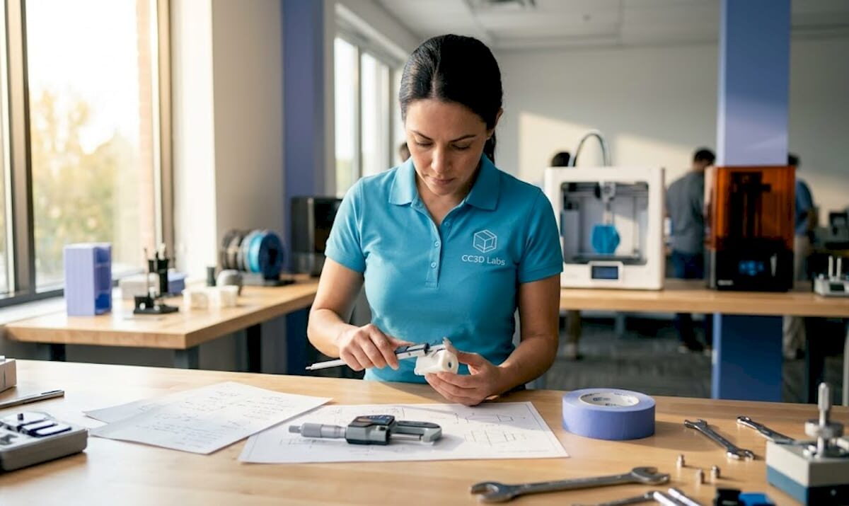
The Role of Part Validation in 3D Printing for Manufacturers


TL;DR:

  • Part validation in 3D printing ensures a process consistently produces conforming parts, not just individual successful prints.
  • Implementing structured IQ/OQ/PQ procedures and using multiple validation techniques reduces scrap, enhances quality, and meets regulatory standards.

Most manufacturers assume that once a 3D printer finishes a job, the part is ready to use. That assumption is expensive. The role of part validation in 3D printing is far more critical than most production teams realize, and the gap between “it printed” and “it works reliably” is where quality problems, warranty failures, and regulatory risks pile up. Projects that skip validation show 3 to 5 times higher scrap rates in the first three months of production. This article breaks down what validation actually involves, which techniques work, and how to build a process that protects your parts and your bottom line.

Table of Contents

Key takeaways

Point Details
Validation goes beyond inspection Process validation confirms repeatable results across all future builds, not just one good part.
Multiple techniques compound accuracy Combining dimensional checks, 3D scanning, and functional testing catches defects that single-method inspection misses.
Business impact is measurable Proper validation dramatically reduces scrap, rework costs, and machine downtime across production runs.
Regulated industries require it Medical, aerospace, and defense applications mandate formal IQ/OQ/PQ validation before production parts ship.
Continuous monitoring sustains quality SPC systems fed by validation data catch process drift before it becomes a defect wave.

The role of part validation in 3D printing explained

Part validation and product inspection are not the same thing, and confusing the two is one of the most common mistakes manufacturers make when scaling from prototype to production. Inspection checks whether a specific part meets specifications. Validation proves that the process consistently produces conforming parts within defined parameters, every time, without relying on 100% inspection to catch failures.

Think of it this way: inspecting one part from a batch of 500 tells you about that one part. Validating the process tells you whether all 500 are likely to be good before you even measure them.

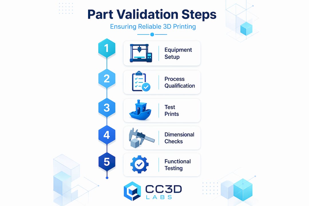
Infographic showing steps in 3D print part validation

In regulated industries, this distinction carries legal weight. Process validation is mandatory for medical devices, aerospace components, and pharmaceutical manufacturing equipment. Regulatory bodies require documented evidence that the process, not just the product, is under control. But even outside those industries, validation is the framework that separates reactive quality control from proactive quality assurance.

The most widely adopted framework is IQ/OQ/PQ, adapted directly from pharmaceutical and medical device manufacturing:

  • Installation Qualification (IQ): Confirms the printer and supporting equipment are installed correctly, calibrated, and operating within manufacturer specifications.
  • Operational Qualification (OQ): Tests whether the process produces conforming parts across the defined operating range, including edge conditions.
  • Performance Qualification (PQ): Demonstrates that the validated process consistently delivers acceptable output under real production conditions over time.

Equipment qualification follows this IQ to OQ to PQ sequence as a prerequisite to process validation, and skipping any stage undermines the entire framework. This structure forces manufacturers to think systematically rather than relying on operator intuition.

Pro Tip: When starting a validation program for 3D printing, document your IQ stage meticulously. Calibration records, environmental conditions, and software version logs protect you during audits and give you a meaningful baseline when troubleshooting future deviations.

Methods for part validation that actually work

Choosing the right validation technique depends on part geometry, material, application criticality, and whether you need destructive or non-destructive data. Most production environments benefit from layering multiple approaches rather than relying on any single method.

Dimensional measurement and 3D scanning

Calipers and coordinate measuring machines (CMMs) remain reliable for straightforward geometries. However, for complex organic shapes, thin walls, or surfaces that require full-field data, structured-light or laser 3D scanning delivers far more information per measurement cycle. Aerospace manufacturers illustrate the scale of this advantage: Boeing has publicly described AI-assisted validation tooling that saves hours of inspection time per aircraft.com/news/how-boeing-is-using-ai-for-rapid-parts-validation/” rel=”nofollow noopener noreferrer” target=”_blank”>AI-powered validation tool saves 17 or more hours per aircraft during inspection, while reducing gauge repeatability and reproducibility variance to 0.93%. That level of measurement consistency would be impossible with manual methods alone.

Functional and mechanical testing

Dimensional accuracy tells you if a part is shaped correctly. Functional testing tells you if it performs correctly under load, temperature, chemical exposure, or repeated cycling. For structural components, this might mean tensile or compression testing. For enclosures, it might mean IP rating validation. Destructive testing is sometimes the only honest way to understand failure modes, particularly for safety-critical parts where the cost of a field failure far exceeds the cost of the test sample.

Statistical process control and capability metrics

  1. Collect baseline data across multiple print runs using consistent measurement methods and operator protocols.
  2. Calculate Cpk and Ppk to quantify how well the process holds critical dimensions within specification limits.
  3. Set up control charts for key process variables like nozzle temperature, layer adhesion, and print speed.
  4. Establish control limits based on your baseline and trigger revalidation when measurements drift outside them.
  5. Feed data back into your process settings to tighten variation over time.

Validation data integrates directly with SPC systems for early detection of variation and continuous process improvement. This transforms validation from a one-time event into an ongoing quality intelligence system.

Pro Tip: Do not target a Cpk of exactly 1.0 when setting your process capability goals. Aim for 1.33 or higher. That margin gives your process room to drift before parts fall out of spec, which means fewer emergency stops and more predictable output.

A comparison of common validation techniques by application:

Technique Best for Destructive? Cost level
CMM dimensional inspection Prismatic, tight-tolerance parts No Medium
Structured-light 3D scanning Complex geometry, full-field data No Medium to high
Tensile and compression testing Structural or load-bearing parts Yes Low to medium
CT scanning Internal features, porosity detection No High
Functional performance testing End-use assemblies, fit checks Sometimes Varies

Learning more about ways to validate 3D designs can help you choose the right combination for your specific production environment.

Business impact of rigorous part validation

The financial argument for validation is not abstract. Filament runout and mid-print failures waste real material and machine time on any print farm, and proper process validation dramatically reduces those losses. That is one failure mode. Multiply it across material inconsistency, temperature variation, and calibration drift, and the cumulative cost of unvalidated 3D printing operations becomes significant.

Manufacturers who build validation into their workflow see measurable improvements across four areas:

  • Scrap and rework reduction: Catching process drift early prevents entire batches from becoming waste. The difference between catching a problem at print cycle 3 versus print cycle 300 is the difference between a minor correction and a production crisis.
  • Customer confidence: Validated parts ship with documented proof of conformance. For product developers sourcing parts from contract manufacturers, this documentation is the difference between an acceptable supplier and a preferred supplier.
  • Regulatory readiness: Companies in medical, aerospace, or defense supply chains cannot bid on regulated contracts without validated processes. Building that infrastructure now opens market doors later.
  • Scalability from prototype to production: A prototype can tolerate variability. A production run cannot. Validation is what makes the transition from “it worked once” to “it works every time.”

Scaling production without validation is like building a house on a foundation you have never tested. It might hold, but you will not know until something fails. A well-documented validation record also reduces engineering review time when design changes trigger revalidation, since your process baseline is already defined.

Challenges in validation and how to address them

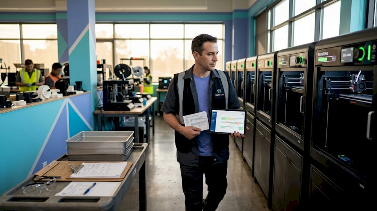
Supervisor reviewing production in 3D print facility

Integrating part validation into a 3D printing workflow is not without friction, especially for manufacturers who built their operations around rapid iteration rather than process rigor.

The most persistent challenge is measurement uncertainty. Knowing that a part is within tolerance requires that your measurement system is itself accurate and repeatable. Misaligned mating parts caused by unclear dimensional definitions often trace back to incomplete GD&T on drawings rather than actual process failures. Fixing the drawing is faster and cheaper than retesting the process, but you have to know which problem you are actually solving.

Environmental variability is another overlooked factor. Humidity, ambient temperature, and even vibration from nearby equipment affect print quality in ways that are invisible until validation data reveals the pattern. This is where the distinction between Factory Acceptance Testing and Site Acceptance Testing becomes practical. FAT confirms equipment performance in a controlled environment, while SAT validates that same performance under your actual production conditions. A printer that passes FAT may still behave differently on your shop floor, and SAT validates real-world performance for long-term stability.

Best practices for making validation sustainable:

  • Start with a risk-based sampling plan. Not every part or every batch needs 100% inspection. Identify your highest-risk features and focus measurement resources there.
  • Define revalidation triggers upfront. Material lot changes, nozzle replacements, firmware updates, and facility moves all warrant revalidation. Write them down before production starts.
  • Build documentation habits early. Validation reports are only useful if they reflect what actually happened. Standardize your data capture formats from day one.
  • Treat print accuracy insights as a continuous feedback loop rather than a pass/fail gate at the end of a run.

Pro Tip: If you are launching a validation program with limited resources, start with your most critical dimension on your most common part. Validate that one feature thoroughly, document your results, and build from there. A narrow validation done well is more useful than a broad validation done superficially.

My take on where validation fits in your strategy

I’ve talked with a lot of manufacturers who treat part validation as something you do for auditors. You prove compliance, file the paperwork, and move on. In my experience, that framing costs them more than they realize.

What I’ve seen work is treating validation as a data collection strategy. Every measurement you take, every capability study you run, every batch you document gives you a clearer picture of what your process is actually doing versus what you think it’s doing. The manufacturers who use that data proactively, adjusting parameters before scrap rates climb rather than after, are the ones who scale 3D printing production without the chaos that typically comes with it.

The other thing I’d push back on is the idea that validation is only for regulated industries. I’ve seen product developers lose significant time and money when a part that worked perfectly in prototyping failed consistently in production, specifically because no one validated the transition. The process that produced five good prototypes is not automatically the same process that will produce five hundred reliable production parts.

Start lean. Start with one part, one critical feature, one documented study. The insights you get from that first real validation run will tell you more about your process than months of informal inspection. And when you’re ready to scale your 3D printing with confidence, you’ll have the data to back every decision.

— Justin

How Cc3dlabs supports your validation needs

Reliable 3D printed parts start with a process built for quality from the first layer to the final inspection. At Cc3dlabs, we bring professional handheld 3D scanning (accuracy to ~0.1 mm), precision filament-based printing, and design support together under one workflow, so product developers and manufacturers get parts they can actually validate.

https://cc3dlabs.com

Whether you need functional prototypes with documented dimensional reports, batch production runs with consistent quality, or scanning services to compare printed parts against CAD geometry, Cc3dlabs has the equipment and experience to back it up. Our 3D printing services are built around the kind of accuracy and repeatability that makes validation straightforward, not a burden. Get a free online estimate today and see how a quality-focused print partner changes what’s possible for your production program.

FAQ

What is part validation in 3D printing?

Part validation in 3D printing is the process of confirming that a print workflow consistently produces parts meeting defined specifications, not just that a single part passed inspection. It focuses on the process, not just the product.

Why do manufacturers skip part validation?

Most manufacturers skip validation because they perceive it as time-consuming or only required for regulated industries. In practice, skipping validation leads to 3 to 5 times higher scrap rates in early production, making it far more costly than the validation itself.

What methods are used for part validation in 3D printing?

Common methods include CMM dimensional inspection, structured-light 3D scanning, functional mechanical testing, CT scanning for internal features, and statistical process control using Cpk metrics to track process capability over time.

How does the IQ/OQ/PQ framework apply to 3D printing?

IQ confirms correct printer installation and calibration, OQ tests the process across its operating range, and PQ demonstrates consistent output under real production conditions. This sequence is a prerequisite for regulatory compliance and is increasingly adopted in non-regulated 3D printing operations as a best practice.

When should a manufacturer revalidate their 3D printing process?

Revalidation is required after material lot changes, equipment repairs or replacements, firmware or software updates, facility moves, and any design changes that affect critical dimensions. Documenting these triggers upfront prevents gaps in your quality record.