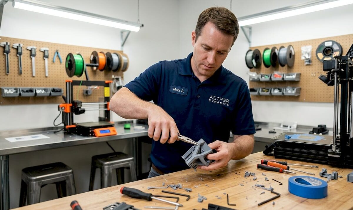
Engineer finishing part in 3D printing workspace

Top tips for low-volume manufacturing with 3D printing


TL;DR:

  • Low-volume manufacturing demands high precision, speed, and process discipline for successful outcomes.
  • Optimizing 3D printing parameters and selecting suitable materials and technologies are crucial for quality parts.
  • Each low-volume run requires meticulous workflow management and strict process control to ensure repeatability.

When you need functional parts fast and in small quantities, the margin for error shrinks fast. Product developers and small manufacturers face a specific pressure: high-volume production tools don’t apply, yet the quality bar stays exactly the same. 3D printing closes that gap, but only when you apply the right strategies. Optimal FDM settings yield a Young’s modulus of 3400 MPa and tensile strength of 51 MPa, proving that parameter discipline directly determines part performance. The difference between a successful low-volume run and an expensive redo often comes down to process knowledge.

Table of Contents

Key Takeaways

Point Details
Focus on infill Infill density dramatically shapes part strength and efficiency in low-volume manufacturing.
Tune process settings Process parameters like speed, temperature, and orientation directly impact prototype quality.
Choose technology wisely SLS 3D printing is ideal for strong, functional parts while SLA excels in detail and finish.
Streamline workflow Efficient CAD prep and quality checks accelerate turnaround and minimize costly errors.
Partner for success Expert help and proven solutions ensure low-volume projects stay on time and on target.

Key criteria for low-volume manufacturing success

Before jumping into specific tips, it helps to define what success actually looks like for low-volume manufacturing. The criteria are different from high-volume production in ways that catch many teams off guard.

Precision is the first pillar. At low volumes, you don’t have statistical averaging across thousands of parts to smooth out variation. Every single part carries full weight. Tolerances that seem acceptable in theory become costly in practice when a mating component doesn’t fit on the assembly line.

Speed is the second. Low-volume runs skip the expensive tooling and setup time of injection molding, but that advantage disappears if your 3D printing workflow isn’t optimized. Lead time discipline matters just as much as print time.

Cost distribution works differently here too. Setup costs, material waste, and post-processing hours get spread across fewer parts, so each unit carries more overhead. Choosing the wrong approach can make low-volume printing more expensive than it needs to be.

Repeatability is where most teams underestimate the challenge. Even with the same file and the same machine, small process variations can produce inconsistent results. Infill density alone accounts for up to 25.66% of the contribution to mechanical strength, meaning a small setting change ripples through your entire batch.

Here’s a quick checklist to assess your project before you start:

  • Define your dimensional tolerances before selecting a process
  • Identify whether the part is functional, aesthetic, or both
  • Estimate your acceptable cost per unit at your target quantity
  • Confirm your lead time requirements against your service provider’s capacity
  • Decide whether surface finish matters for fit, function, or customer presentation

The most common mistake in low-volume manufacturing is treating it like a scaled-down version of mass production. It isn’t. It’s a different discipline with different tradeoffs, and the teams that recognize that early save significant time and money.

For a deeper look at how design choices affect outcomes, the guidance on reliable 3D print design covers the foundational decisions that set your project up for success from the start.

Optimize 3D printing process parameters

Once you know what matters most for your parts, the next step is tailoring your 3D printing parameters for maximum performance. This is where many teams leave significant quality on the table by using default settings.

For FDM printing with PLA, research-backed optimal FDM PLA settings point to a nozzle temperature of 210°C, print speed of 30mm/s, layer height of 0.1mm, and a 0° raster angle. These settings consistently produce parts with tensile strength of 51 MPa and a Young’s modulus of 3400 MPa. That’s not just a lab number. It translates directly to real-world part durability.
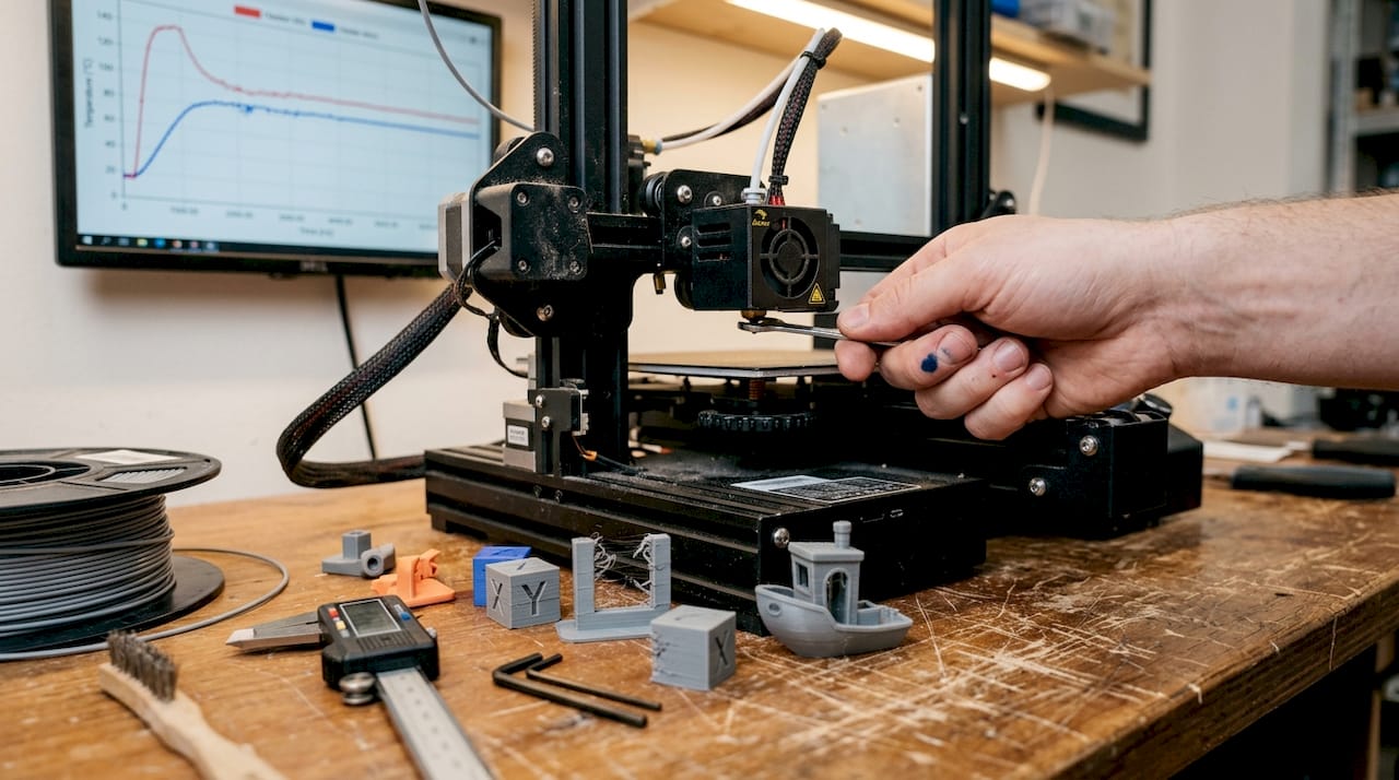
Hand adjusting FDM 3D printer nozzle detail

Here’s a quick parameter reference to guide your setup:

Parameter Recommended setting Impact
Nozzle temperature 210°C (PLA) Affects layer adhesion and flow
Print speed 30 mm/s Slower speeds improve bonding
Layer height 0.1 mm Finer layers increase precision
Raster angle Maximizes tensile strength
Infill density 20-50% (functional) Strongest predictor of strength

Part orientation is another variable that product developers often overlook. Printing a part flat versus upright changes where the layer lines run relative to the load direction. For parts that experience bending or tension, orienting the strongest axis along the load path can make a measurable difference in service life.

Pro Tip: Use conservative parameters (lower speed, higher infill) for end-use functional parts, and faster, lower-infill settings for early-stage appearance prototypes. This lets you move quickly on concept validation without burning material budget on parts that will change anyway.

For a full breakdown of how each variable interacts, the 3D printing parameter guide walks through the logic behind each setting in practical terms. If you’re still getting familiar with the vocabulary, the 3D printing terminology resource is a solid starting point before diving into parameter tuning.

Select the best 3D printing technology and materials

Optimizing your process only works if you start with the right technology and materials. The choice between FDM, SLA, and SLS isn’t just a cost question. (A note on scope: our own production at CC 3D Labs runs on a calibrated FDM print farm — we cover SLA and SLS here so you can compare processes, and if your part genuinely needs one of them, we’ll say so and point you to the right provider.) It shapes what your part can actually do.

SLS offers stronger mechanics for functional parts, while SLA excels in surface aesthetics and fine detail. FDM sits in the middle, offering the widest material range and lowest cost, but with visible layer lines and more post-processing for smooth finishes.

Here’s a side-by-side comparison to help you decide:

Technology Strength Surface finish Cost Best for
FDM Moderate Visible layers Low Functional prototypes, enclosures
SLA Moderate Excellent Medium Aesthetic models, dental, jewelry
SLS High Good Higher Functional end-use parts, complex geometry

Material selection matters just as much as technology. Here’s a quick breakdown:

  • PLA: Easy to print, good for visual prototypes, not ideal for heat or impact
  • PETG: Better chemical resistance and flexibility than PLA, great for functional parts
  • ABS: Strong and heat-resistant, but warps without enclosure control
  • Advanced polymers (Nylon, TPU, PC): For demanding functional applications requiring flexibility, high heat, or impact resistance

Matching your material to your application is non-negotiable. A housing that looks identical in PLA and PETG will behave very differently in a warm environment or under repeated stress. For a detailed comparison of how materials hold up under real conditions, the guide on material selection for durability is worth reviewing before you finalize your spec. If you’re still deciding between technologies, the printing technology comparison breaks down the tradeoffs in practical terms.

Streamline workflow for precision and fast turnaround

With your process and materials set, integrating smart workflow habits will unlock true low-volume agility. The gap between a smooth run and a frustrating one is usually in the steps before and after printing.

Here’s a proven workflow sequence for low-volume 3D printing runs:

  1. Design for manufacturing (DFM) review: Check wall thickness, overhangs, and feature sizes before sending any file. Catching a design issue at this stage costs nothing. Catching it after printing costs time and material.
  2. File preparation: Export in STL or STEP format. Check for non-manifold geometry and repair errors using slicer software before submission.
  3. Slicer review: Confirm support placement, layer orientation, and infill settings match your part’s functional requirements.
  4. First article inspection: Print one part first. Measure critical dimensions before committing to the full batch.
  5. Mid-run quality check: For batches above five parts, inspect a sample mid-run to catch any machine drift early.
  6. Post-processing review: Confirm that any sanding, priming, or hardware insertion meets spec before the parts ship or go to assembly.

Tuning every step of the process is what ensures repeatability and reliable part quality, especially at low volume where there’s no buffer for bad parts.

Pro Tip: Before your first production run with a new 3D printing partner, share your tolerance requirements and intended use case upfront. A good partner will flag potential issues before they become reprints. That conversation saves more time than any single parameter tweak.

For teams working with complex file structures or multiple CAD tools, the resource on CAD workflow optimization covers the file format decisions that affect print accuracy from the start.

Why precision matters more in low-volume manufacturing than you think

Here’s a perspective that doesn’t get enough airtime: low-volume manufacturing actually demands more process discipline than high-volume production, not less. That’s counterintuitive, but it’s true.

In mass production, variation averages out. You get thousands of data points, statistical process control kicks in, and outliers get caught before they reach customers. In a 10-part batch, one bad part is a 10% failure rate. Two bad parts and you’ve missed your delivery.

The conventional advice to “move fast and iterate” can backfire badly in this context. Skipping a first article inspection or using default slicer settings to save 20 minutes can produce a batch that fails dimensional checks entirely. The rework cost dwarfs the time saved.

Real-world functional parts require application-specific process control, not just impressive lab benchmarks. The teams that succeed in low-volume manufacturing treat each run with the same rigor they’d apply to a production line. They document settings, track results, and build a process knowledge base that makes every subsequent run faster and more reliable.

Working with a partner who applies that same discipline matters. The design discipline in prototype printing resource reflects exactly this mindset, where the goal is reliable outcomes, not just fast ones.

Take your low-volume manufacturing to the next level with CC3DLabs

Applying these strategies takes expertise, the right equipment, and a partner who treats your 10-part run with the same care as a 1,000-part order. That’s exactly what CC 3D Labs delivers.

https://cc3dlabs.com

Whether you need precision functional prototypes, small-batch production parts, or expert guidance on material and process selection, our 3D printing services are built for product developers who can’t afford to compromise on quality or speed. Explore 3D printing on demand for fast turnaround on custom parts, or see the range of prototypes to functional parts we produce for clients across industries. Request a free online estimate today and put these tips into practice with a team that knows exactly how to execute them.

Frequently asked questions

What is the ideal infill percentage for strong, low-volume 3D printed parts?

For most functional prototypes, an infill of 20-50% balances strength and material efficiency. Infill density is the single most critical parameter for tensile and compressive strength in FDM parts.

Which 3D printing method is best for functional, low-volume parts?

Selective Laser Sintering (SLS) is typically the strongest choice for functional, low-volume parts. SLS outperforms SLA on mechanical properties, while SLA leads on surface aesthetics.

Can adjusting print speed affect the durability of low-volume parts?

Yes, slower print speeds improve inter-layer bonding and increase overall part strength. 30mm/s print speed is the research-backed optimum for PLA FDM parts targeting maximum tensile performance.

What file format should I use for submitting 3D print jobs?

STL and STEP files are the preferred formats for most 3D printing workflows. They ensure broad compatibility with slicer software and preserve dimensional accuracy during file transfer.

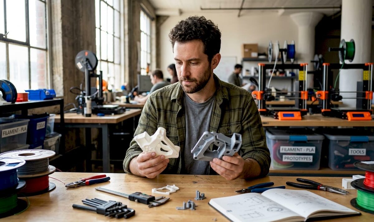
Engineer examines 3D printed prototypes at workbench

Choose the right 3D printing type for prototypes & production


TL;DR:

  • Selecting the appropriate 3D printing process based on project needs is crucial to avoid costly rework.
  • FDM is cost-effective for prototypes and fixtures but has limitations in accuracy and strength direction.
  • Resin-based methods like SLA/DLP excel in surface finish and detail, suitable for visual prototypes and casting masters.

Choosing the wrong 3D printing process can cost you weeks of rework and thousands in wasted material. For product developers moving from concept sketches to functional prototypes and into low to mid-volume production, the stakes are real. FDM, SLA, SLS, MJF, DMLS — each process delivers a different combination of accuracy, surface finish, material strength, and cost per part. Pick the wrong one and your prototype won’t test what you need it to test. This guide breaks down every major printing type, the technical benchmarks that separate them, and a clear framework for matching process to project goals.

Table of Contents

Key Takeaways

Point Details
Selection framework Match print process to function, tolerance, strength, and finish for best results.
FDM for prototypes FDM/FFF offers the lowest cost and largest build volumes for design validation and jigs.
SLA/DLP for detail SLA and DLP provide the finest accuracy and smoothest surface for visual prototypes.
Powder bed for function SLS/MJF excel in functional nylon parts and DMLS/SLM leads for metal.
Comparison tools Use quick-reference tables to compare tolerances, properties, and applications for each 3D printing type.

How to evaluate 3D printing types: Key criteria

Before comparing technologies, you need a structured way to filter them. The right process depends on a combination of factors, and skipping this step leads to expensive mismatches between what the print can deliver and what your part actually needs.

Here are the core criteria to assess before selecting a process:

  • Intended function: Is this a visual mock-up, a fit/form check, a functional stress test, or an end-use production part?
  • Mechanical properties: Tensile strength, flexural modulus, impact resistance, and isotropy all vary significantly by process.
  • Surface finish: Measured in Ra (roughness average), finish affects aesthetics, sealing, and post-processing requirements.
  • Dimensional tolerance: Critical for mating parts, press fits, and precision assemblies.
  • Part size: Build envelope limits differ widely — FDM machines can print large enclosures; resin printers are typically smaller.
  • Material options: Engineering polymers, flexible TPU, high-temp resins, metal alloys — process determines what’s available.
  • Budget and volume: Cost per part drops with some processes at volume; others stay flat.

A useful way to think about this: tolerance requirements alone can cut your list in half. Types of 3D printing for prototypes and production show that SLA achieves ±0.05mm, SLS and MJF land around ±0.2–0.25mm, and FDM typically runs ±0.5mm. If your part has tight mating tolerances, FDM is off the table immediately.

Anisotropy — the directional difference in mechanical strength — is another filter most teams miss early. Parts printed in FDM are significantly weaker in the Z direction. SLS and MJF are near-isotropic, meaning strength is consistent regardless of build orientation. Understanding this upfront shapes not just process selection but also part orientation strategy.

Post-processing needs matter too. Sanding, priming, dyeing, and support removal all add time and cost. Knowing how to pick the right process before you send a file saves iterations. For early-stage teams, a solid quick prototyping guide can clarify how process selection ties directly to development speed.

Extrusion-based printing (FDM/FFF): Workhorse for prototypes and jigs

FDM (Fused Deposition Modeling) and its open-source counterpart FFF (Fused Filament Fabrication) work by melting a thermoplastic filament and depositing it layer by layer. The process is straightforward, scalable, and compatible with a wide range of engineering-grade materials including PLA, PETG, ABS, ASA, Nylon, TPU, and high-temp options like PEEK.

Strengths of FDM for engineering applications:

  • Lowest cost per part among all major processes
  • Widest range of build volumes — some industrial FDM machines exceed 1,000mm in a single axis
  • Broad material library with well-documented mechanical properties
  • Fastest turnaround for large, low-detail parts

Limitations to plan around:

  • Visible layer lines require sanding or coating for smooth surfaces
  • Z-axis weakness due to layer adhesion — parts can delaminate under load
  • Tolerances of ±0.5mm limit use in precision assemblies

FDM is the cost-effective choice for jigs, fixtures, enclosures, and early-stage prototypes where geometry validation matters more than surface quality. The FDM process mechanics — including temperature control, support structures, and layer adhesion — are well understood, which makes troubleshooting predictable.

“FDM gives development teams the fastest path from CAD to physical object at a price point that supports multiple design iterations without budget pressure.”

Pro Tip: Reorienting a part 45 degrees and adjusting infill pattern can boost effective tensile strength by up to 20% without changing material or process. This is one of the most underused levers in FDM design.

For teams choosing between materials, understanding the tradeoffs between FDM materials like PLA, PETG, and ABS directly affects whether the prototype survives functional testing or fails at the first load cycle.

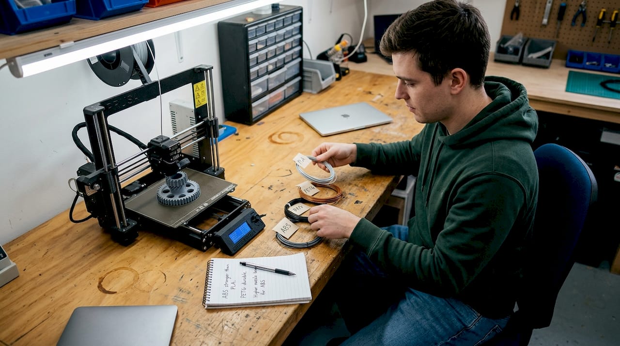
Professional comparing FDM 3D printing materials

Photopolymerization (SLA/DLP): Precision and surface detail

SLA (Stereolithography) uses a UV laser to cure liquid resin point by point, while DLP (Digital Light Processing) flashes an entire layer at once using a projector. Both produce parts with exceptional surface quality, but the mechanics create meaningful differences in speed and accuracy.

Key advantages of resin-based printing:

  • Surface finish as low as Ra 1–3µm — the smoothest of any common 3D printing process
  • SLA achieves ±0.05mm tolerance, DLP typically ±0.10mm
  • Excellent for fine features, thin walls, and complex organic geometry
  • Ideal for casting masters, dental models, and visual presentation prototypes

Where resin processes fall short:

  • Most standard resins are brittle and not suited for load-bearing applications
  • UV exposure over time degrades mechanical properties — outdoor use is limited
  • Build volumes are smaller than FDM, limiting large-part applications
  • Post-curing is required, which adds time and affects final properties

A 2025 flexural study found SLA flexural strength at 93MPa, outperforming DLP at 70MPa — a meaningful gap when you’re validating parts that need to flex under load. DLP’s speed advantage makes it attractive for batch runs of small, detailed parts where per-layer cure time is the bottleneck.

Pro Tip: Post-curing under controlled UV exposure increases hardness and flexural strength, but over-curing increases brittleness. Run a calibration cure test on sample parts before committing to a full batch.

For teams who need to communicate surface finish definitions to clients or manufacturing partners, understanding Ra values and how they map to process output prevents misaligned expectations at review.

Powder bed fusion (SLS, MJF, DMLS/SLM): From functional polymers to metal parts

Powder bed fusion covers a family of processes that fuse material layer by layer from a powder bed. No support structures are needed for polymers — the surrounding powder acts as support — which enables highly complex geometries that other processes can’t achieve.

SLS (Selective Laser Sintering) uses a CO2 laser to sinter nylon powder. It produces parts with ±0.25mm tolerance and tensile strength around 48MPa for PA12. Parts are durable, chemically resistant, and suitable for functional testing and low-volume production runs.

MJF (Multi Jet Fusion) uses inkjet-deposited fusing agents activated by infrared energy. It’s faster than SLS, produces denser parts, and achieves near-isotropic mechanical properties — meaning orientation during printing has minimal effect on strength. This matters enormously for end-use parts.

DMLS/SLM uses a fiber laser to fuse metal powder — titanium alloys, stainless steel, Inconel, aluminum. Parts reach >99.5% density with tolerances of ±0.10mm, making them viable for aerospace, medical, and industrial end-use applications.

Powder bed processes offer the best combination of geometric freedom and mechanical isotropy for functional polymer and metal parts — a combination no other process family can match at this scale.

Process Tolerance Key material Relative cost Best use case
SLS ±0.25mm PA12 Nylon Medium Functional prototypes, low-run production
MJF ±0.20mm PA12, PA11 Medium-high End-use parts, near-isotropic loads
DMLS/SLM ±0.10mm Ti6Al4V, steel High Metal qualification, aerospace, medical

For teams working on functional polymer and metal prints, SLS and MJF are often the bridge between prototype validation and production-ready components. The SLS and MJF mechanics — including powder management, thermal stress, and post-processing — require more process knowledge than FDM but reward that investment with significantly better part performance.

Quick reference comparison: Picking the right 3D printing process

With all four major process families covered, here’s a consolidated view for engineering teams making a final call.

Process Tolerance Surface finish Cost tier Production fit
FDM ±0.5mm Moderate (Ra 10–20µm) Low Prototypes, jigs, fixtures
SLA ±0.05mm Excellent (Ra 1–3µm) Medium Visual prototypes, casting masters
DLP ±0.10mm Excellent (Ra 1–3µm) Medium Detailed small parts, dental
SLS/MJF ±0.20–0.25mm Good (Ra 6–10µm) Medium-high Functional parts, low-volume runs
DMLS/SLM ±0.10mm Good (Ra 4–10µm) High Metal end-use, qualification parts

Based on tolerance and cost benchmarks across processes, here are scenario-based recommendations:

  1. Visual prototype for stakeholder review: Use SLA or DLP. Surface quality and accuracy make the part presentation-ready without secondary finishing.
  2. Fit and form check on an assembly: FDM is fast and cheap enough to iterate. If tolerance is critical, step up to SLA.
  3. Functional part for stress or environmental testing: SLS or MJF. Near-isotropic nylon parts survive real-world loads and chemicals.
  4. Metal part qualification for production: DMLS/SLM. The density and tolerance match machined metal for most non-critical applications.
  5. Special cases: Binder Jetting works well for full-color models and metal sintering at lower cost than DMLS. PolyJet handles multi-material and overmold simulations. Both are worth considering when standard processes don’t fit.

Exploring real-world 3D printing applications across industries shows how these process choices play out in practice. For teams ready to act, reviewing on-demand project examples gives a concrete sense of what each process delivers at production scale.

Our take: Why context matters more than specs in 3D printing selection

Datasheets are a starting point, not a decision. We’ve seen engineers spend weeks comparing tolerance specs between SLS and MJF for a prototype that only needed to survive two weeks of fit testing. The 0.05mm difference was irrelevant. What mattered was turnaround time and cost per iteration.

The limitations people worry about most — anisotropy in FDM, brittleness in SLA resins — are often manageable with smart design choices. Anisotropy becomes an advantage when you orient a part so the load direction aligns with the strongest axis. Resin brittleness stops being a problem when the part is a casting master, not a structural component.

Our honest advice: run a test iteration before committing to a process for a full batch. A single test print reveals more than any datasheet. And revisit process selection as your design matures. What works for a first-round prototype often isn’t the right call for a 500-unit production run. Focus on fit-for-purpose, and let the design evolution guide the process evolution. For teams navigating that transition, working through bespoke 3D print jobs with experienced partners accelerates that learning significantly.

Get expert 3D printing for your next project

At CC 3D Labs, we work with product developers and engineers across every stage of the product lifecycle — from first-round prototypes to low and mid-volume production runs. Whether you need FDM for rapid iteration, SLA for presentation-quality parts, or specialty materials for functional testing, we match the process to your actual requirements, not just the closest available option.

https://cc3dlabs.com

We handle custom material requests, multi-color printing, and CAD support for teams that need more than a file upload and a quote. If you’re unsure which process fits your current project, explore our 3D printing services or browse what parts are printable for your application. Ready to move? Submit your file and project details through our on-demand custom projects page for a fast, accurate estimate.

Frequently asked questions

Which 3D printing type delivers the strongest mechanical properties for end-use parts?

SLS and MJF produce near-isotropic nylon parts that approach injection-molded strength, while DMLS/SLM yields metal components with greater than 99.5% density for demanding structural applications.

What are the main limitations of FDM versus SLS or SLA?

FDM is weaker along the Z axis and shows visible layer lines, while SLS offers better isotropy and SLA provides the best surface finish but lower load-bearing capacity. Each process has tradeoffs that make it better suited for specific applications.

How do I choose the best 3D printing type for visual prototypes?

SLA delivers the finest detail and smoothest surface finish for visual prototypes, making it the top choice when appearance and dimensional accuracy are the primary goals.

Are 3D printed materials suitable for outdoor or high-temperature use?

Engineering polymers like PEEK and metals like Ti6Al4V handle high temperatures reliably, but SLA resins degrade under prolonged UV exposure and are not recommended for outdoor applications without protective coating.

Can powder bed fusion create both polymer and metal parts?

Yes. SLS and MJF process nylon and other polymer powders for durable functional parts, while DMLS and SLM fuse metal powders to produce dense, high-strength metal components.

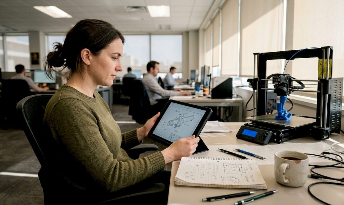
Engineer reviewing CAD model near 3D printer

What is additive manufacturing? A guide for businesses

Many businesses confuse additive manufacturing with simple 3D printing, missing its full potential for product development and custom fabrication. Additive manufacturing builds objects layer by layer rather than cutting away material, offering capabilities that extend far beyond desktop hobbyist printers. This guide clarifies the complete scope of additive technologies, explains how different methods work, and shows you practical applications for prototyping, functional parts, and batch production. You’ll discover which technologies fit your needs and how to integrate additive processes into your existing workflows.

Table of Contents

Key Takeaways

Point Details
Definition and scope Additive manufacturing builds objects by depositing material layer by layer from a digital model, offering capabilities beyond traditional subtractive methods.
Main technologies FDM, SLA, and SLS are the three dominant methods, each suited to different applications and outcomes.
Practical business uses Prototyping functional parts and batch production are common business applications enabled by additive manufacturing.
Benefits and considerations The technology enables customization, faster iteration, and reduced waste while requiring workflow integration and material selection planning.

What is additive manufacturing? Definition and key concepts

Additive manufacturing creates physical objects by depositing material in successive layers based on a digital 3D model. Unlike subtractive manufacturing, which removes material through cutting, milling, or drilling, additive processes build parts from the ground up. This fundamental difference enables production of geometries impossible with traditional methods, including internal channels, lattice structures, and consolidated assemblies that would normally require multiple components.

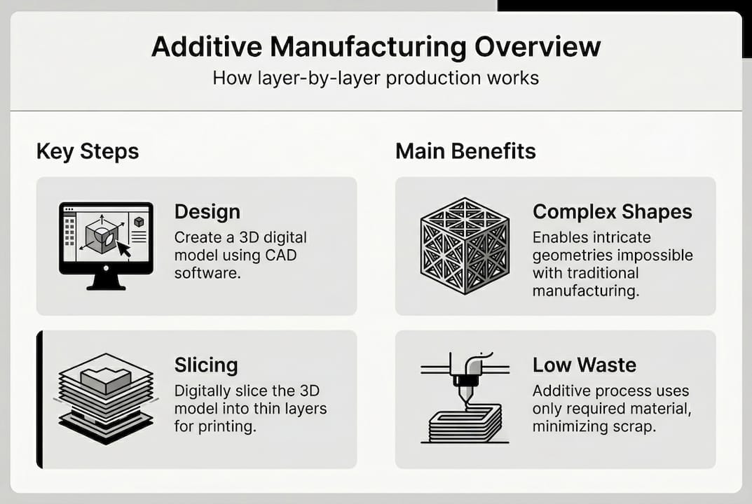
The process starts with a CAD file that defines the part geometry. Slicing software divides this model into thin horizontal layers, generating toolpaths that guide the manufacturing equipment. The machine then deposits, cures, or fuses material layer by layer until the complete object emerges. Each technology uses different materials and bonding methods, but all follow this core principle of incremental addition.

Formative manufacturing, the third major category, shapes material through molding or casting. Additive manufacturing eliminates tooling costs associated with formative processes, making it economical for small production runs and one-off custom parts. You can iterate designs quickly without investing in new molds or fixtures.

Popular additive manufacturing methods include fused deposition modeling, stereolithography, and selective laser sintering, each suited to different applications. FDM extrudes thermoplastic filament through a heated nozzle, building parts that balance strength with affordability. SLA uses ultraviolet lasers to cure liquid resin into solid layers, achieving fine detail and smooth surfaces. SLS employs lasers to fuse powder particles, producing durable parts without support structures.

The technology excels at producing complex geometries that would require extensive machining or assembly with conventional methods. Internal cooling channels, organic shapes mimicking natural structures, and parts with variable wall thickness become straightforward. On-demand 3D printing services let you manufacture these complex designs without capital equipment investment.

Infographic showing additive manufacturing overview

Pro Tip: Start your additive manufacturing journey by identifying parts in your current product line that require extensive machining or assembly. These often benefit most from consolidation into single printed components.

Key process components include design preparation, where you optimize models for layer-based fabrication, material selection based on mechanical requirements and operating environment, build preparation involving orientation and support structure generation, and post-processing such as support removal, surface finishing, or heat treatment. Understanding each step helps you plan realistic timelines and budgets for additive projects.

Common additive manufacturing technologies and how they work

Three dominant technologies serve most business applications, each offering distinct advantages for specific use cases. Understanding their differences helps you select the right process for your parts.

Fused deposition modeling extrudes thermoplastic filament through a heated nozzle that moves in the X and Y axes while the build platform lowers incrementally along the Z axis. The extruded material bonds to the previous layer as it cools. FDM machines range from desktop units to industrial systems with heated chambers for engineering-grade materials. Common filaments include PLA for concept models, PETG for functional prototypes, and nylon or polycarbonate for end-use parts requiring strength and temperature resistance.

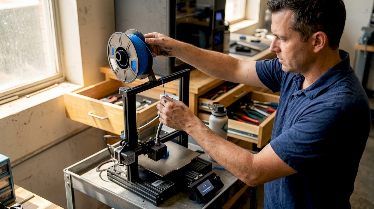
Technician loading filament into FDM 3D printer

Stereolithography cures photosensitive resin using ultraviolet lasers or digital light projection. A build platform starts just below the resin surface, rising incrementally as each layer cures. SLA produces the smoothest surface finish and finest details among common technologies, making it ideal for master patterns, jewelry, and dental applications. Resin properties vary widely, from rigid and brittle to flexible and tough, with specialty formulations for high temperature resistance or biocompatibility.

Selective laser sintering fuses powder particles using a laser that traces each layer’s cross-section. After completing a layer, a roller spreads fresh powder and the build platform lowers. Unfused powder supports the part during building, eliminating separate support structures. SLS parts exhibit consistent properties in all directions and can include features like living hinges. Nylon 12 dominates SLS applications due to its balance of strength, flexibility, and chemical resistance.

Technology Process Materials Typical Uses Key Advantages Limitations
FDM Extrudes melted filament Thermoplastics (PLA, PETG, nylon, PC) Functional prototypes, jigs, fixtures Cost-effective, wide material range, strong parts Visible layer lines, anisotropic strength
SLA UV laser cures liquid resin Photopolymer resins Detailed models, patterns, dental/jewelry Smooth finish, fine details, varied resins Brittle materials, post-cure required
SLS Laser fuses powder particles Nylon, TPU, composites Functional parts, low-volume production No supports needed, isotropic properties Rough surface, limited materials

Material selection drives technology choice as much as part requirements. Engineering-grade 3D printing uses advanced materials like carbon fiber composites, glass-filled nylons, and high-temperature polymers that demand precise process control. Standard desktop FDM handles commodity plastics well, but engineering materials often require enclosed heated chambers to prevent warping.

Build volume constraints affect part size and orientation. Desktop FDM printers typically offer 200-300mm cubes, while industrial systems reach 500mm or larger. SLA build volumes tend toward smaller sizes due to resin vat limitations, though large-format systems exist for specific applications. SLS machines generally provide mid-range build volumes with the advantage of nesting multiple parts in a single build.

Multi-material 3D printing expands design possibilities by combining different colors or material properties in a single build. Dual-extrusion FDM systems can print rigid and flexible materials together or use dissolvable supports for complex geometries. This capability enables overmolded assemblies, color-coded prototypes, and parts with variable shore hardness.

Pro Tip: Match technology to your part’s critical requirements. Need fine surface detail? Choose SLA. Require maximum strength and durability? Select SLS. Want cost-effective functional testing? FDM delivers the best value for most engineering applications.

Post-processing requirements vary significantly. FDM parts often need support removal and may benefit from acetone vapor smoothing or sanding. SLA parts require washing to remove uncured resin, then UV post-curing to achieve full mechanical properties. SLS parts emerge ready to use after depowdering, though you might add dyeing, vapor smoothing, or infiltration for specific applications.

Advantages and limitations of additive manufacturing for businesses

Additive manufacturing transforms product development by compressing design iteration cycles. Traditional prototyping requires tooling fabrication, setup time, and minimum order quantities that slow feedback loops. You can print a design revision overnight, test it the next day, and implement improvements immediately. This speed advantage compounds over multiple iterations, reducing time to market by weeks or months.

Design freedom represents additive manufacturing’s most significant benefit. You can create parts with internal features, undercuts, and organic shapes that would be impossible or prohibitively expensive with conventional methods. Topology optimization algorithms generate lightweight structures that use material only where stress analysis indicates it’s needed, producing parts that might weigh 40-60% less than traditionally manufactured equivalents while maintaining strength.

Customization becomes economical at any volume. Additive manufacturing reduces waste and allows for rapid iteration but may have scaling challenges for mass production. Each part can incorporate unique features without tooling changes or setup costs. Medical devices, custom orthotics, and personalized consumer products leverage this capability to deliver tailored solutions.

Material waste drops dramatically compared to subtractive processes. CNC machining might remove 90% of a billet to create complex parts, sending expensive material to recycling. Additive processes use only the material needed for the part itself plus supports, with some technologies like SLS allowing powder reuse. This efficiency matters both economically and environmentally.

Inventory reduction follows naturally from on-demand production capability. Instead of warehousing spare parts for products that might need service years later, you can store digital files and print replacements as needed. This approach eliminates obsolescence risk and carrying costs while ensuring parts availability.

Production speed limitations constrain high-volume manufacturing. A part that takes 30 seconds on an injection molding line might require 4 hours to print. For quantities above 500-1000 units, traditional manufacturing usually proves more economical. The crossover point depends on part complexity, size, and material requirements.

Material properties sometimes fall short of traditionally manufactured equivalents. FDM parts exhibit anisotropy, with strength varying based on build orientation and layer adhesion. While engineering materials close this gap, critical structural components may still require conventional manufacturing for maximum reliability. Material selection remains more limited than the thousands of alloys, plastics, and composites available for traditional processes.

Surface finish and dimensional accuracy vary by technology. FDM produces visible layer lines that may require post-processing for aesthetic applications. SLS parts have a grainy texture from sintered powder. SLA offers the smoothest finish but may show support attachment points. Tolerances typically range from ±0.1mm to ±0.5mm depending on technology, geometry, and size, compared to ±0.01mm achievable with precision machining.

Pro Tip: View additive manufacturing as a complement to traditional processes rather than a complete replacement. Use it where it excels: complex geometries, customization, rapid iteration, and low to medium volumes. Transition to conventional manufacturing when volumes justify tooling investment.

How businesses incorporate additive manufacturing into product development

Successful integration starts with identifying suitable applications within your existing product portfolio and development pipeline. Follow this systematic approach:

  1. Audit current products and processes to find candidates where additive manufacturing offers clear advantages: parts requiring extensive machining, components with long lead times, products needing customization, or assemblies that could be consolidated.

  2. Create or obtain CAD models optimized for additive processes. Companies integrate additive manufacturing into existing CAD workflows to accelerate product development. Design for additive manufacturing differs from conventional design rules: you can eliminate draft angles, incorporate complex internal features, and use organic shapes that reduce stress concentrations.

  3. Select appropriate technology and material based on part requirements. Consider mechanical properties needed, surface finish expectations, dimensional accuracy requirements, operating environment, and production volume. Match these needs against technology capabilities outlined earlier.

  4. Prepare digital files using slicing software that converts CAD models into machine instructions. This step involves choosing build orientation to optimize strength and surface finish, generating support structures where needed, and setting process parameters like layer height, infill density, and print speed.

  5. Print initial prototypes and conduct functional testing. Evaluate dimensional accuracy, mechanical performance, surface quality, and assembly fit. Document any deviations from design intent or performance requirements.

  6. Iterate designs based on test results. Additive manufacturing makes design changes trivial compared to retooling conventional processes. Adjust wall thickness, add reinforcement ribs, modify snap fits, or refine surface features without cost penalties.

  7. Scale production appropriately. For low volumes, continue printing in-house or through service providers. For higher volumes, consider multiple machines running simultaneously or transition to conventional manufacturing using printed parts as master patterns.

Agile product development methodologies pair naturally with additive manufacturing’s iteration speed. You can validate concepts with stakeholders using physical models rather than renderings, conduct user testing with functional prototypes, and refine ergonomics through rapid design cycles. This approach reduces risk by identifying issues before committing to production tooling.

Functional testing applications extend beyond aesthetics to genuine engineering validation. Print parts in production-intent materials, subject them to mechanical testing, thermal cycling, or chemical exposure, and gather performance data that informs final design decisions. Some companies print functional parts for field testing, collecting real-world usage data before manufacturing investment.

Custom 3D printing services provide access to industrial-grade equipment and expertise without capital investment. Professional providers offer material selection guidance, design optimization consulting, and quality assurance that ensures consistent results. This partnership model works well for companies ramping up additive manufacturing use before justifying in-house equipment.

Low-volume production represents a growing application as material properties and process reliability improve. Bridge manufacturing uses additive processes to fulfill initial orders while production tooling is fabricated. Spare parts production for legacy products, custom medical devices, and specialized industrial components increasingly rely on additive manufacturing for economic production at volumes below traditional minimums.

3D modeling and CAD services help businesses lacking internal design resources. Service providers can reverse-engineer existing parts through 3D scanning, create CAD models optimized for additive manufacturing, and prepare production-ready files. This support accelerates adoption for companies without dedicated engineering staff.

Best practices for integration include establishing design guidelines specific to your chosen technologies, creating a digital library of successfully printed parts to inform future designs, documenting process parameters that produced optimal results, and training team members on additive manufacturing capabilities and limitations. Consider starting with non-critical applications to build expertise before tackling mission-critical components.

Supply chain implications deserve attention. On-demand 3D printing services enable distributed manufacturing, where you send files to service providers near end users rather than shipping physical inventory globally. This approach reduces logistics costs and lead times while enabling mass customization.

Explore custom additive manufacturing solutions with CC3DLabs

Now that you understand how additive manufacturing transforms product development, consider how professional services can accelerate your implementation. CC3DLabs specializes in 3D printing services tailored for businesses and product developers who need reliable, high-quality results without investing in equipment and expertise development.

https://cc3dlabs.com

Our custom 3D printing services handle everything from initial concept models to functional prototypes and low-volume production runs. We work with you to select optimal technologies and materials for your specific requirements, ensuring parts meet mechanical, aesthetic, and dimensional specifications. Whether you need rapid turnaround for design validation or consistent quality for batch production, our team delivers the precision and reliability your projects demand. Complement printing services with our 3D modeling and CAD services to optimize designs for additive manufacturing or reverse-engineer existing parts. Contact us to discuss how additive manufacturing can solve your specific product development challenges.

What is additive manufacturing? Frequently asked questions

What is the difference between 3D printing and additive manufacturing?

Additive manufacturing is the industrial term encompassing all layer-based fabrication technologies, while 3D printing originally referred to desktop hobbyist equipment. Today, the terms are often used interchangeably, though additive manufacturing typically implies professional-grade processes and materials for functional applications rather than decorative models.

What materials are commonly used in additive manufacturing?

Thermoplastics like PLA, PETG, nylon, and polycarbonate dominate FDM applications. Photopolymer resins serve SLA processes, with formulations ranging from rigid to flexible and standard to high-temperature resistant. SLS primarily uses nylon 12 powder, with specialty options including glass-filled composites and thermoplastic polyurethanes for flexible parts.

Which industries benefit most from additive manufacturing?

Aerospace, medical devices, automotive, and consumer products lead adoption due to needs for rapid prototyping, customization, and complex geometries. Aerospace values weight reduction through topology optimization, medical devices require patient-specific customization, automotive uses it for tooling and low-volume performance parts, and consumer products leverage it for design iteration speed.

How long does prototyping with additive manufacturing typically take?

Simple parts print in hours, while complex or large components may require 24-48 hours of machine time. Total turnaround includes design preparation, printing, post-processing, and shipping. Professional services typically deliver prototypes within 3-7 business days from file submission, though rush services can compress this to 24-48 hours for urgent needs.

How does additive manufacturing enable product customization?

Each printed part can incorporate unique features without tooling changes or setup costs that make customization expensive with traditional manufacturing. You simply modify the digital file to adjust dimensions, add personalization, or alter functional features. This capability enables mass customization where every unit differs based on individual customer requirements or application-specific needs.

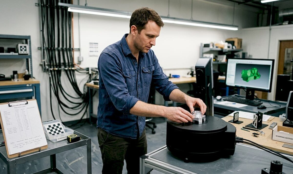
Technician prepares part in 3D scanning lab

How we achieve a high quality 3D scan for manufacturing

Achieving precision in 3D scanning can transform your manufacturing workflow, but many product developers struggle with incomplete data, reflective surface challenges, and uncertainty about scan accuracy. This comprehensive guide walks you through every step of the high quality 3D scan process, from surface preparation and equipment setup to execution, troubleshooting, and verification. You’ll learn proven techniques to capture complete geometry, handle difficult materials, and validate scan quality using quantitative metrics. Whether you’re creating prototypes or functional parts, mastering these methods ensures your scans deliver the accuracy your projects demand.

Table of Contents

Key Takeaways

Point Details
Preparation boosts accuracy Thorough preparation reduces missing geometry and data noise before you scan.
Surface handling strategies Apply scanning spray to reduce reflectivity and use adhesive markers to aid alignment across passes.
Plan multi angle scans Plan scan passes from multiple angles to capture geometry with sufficient overlap for full data.
Post scan verification Evaluate scan quality with quantitative metrics to confirm completeness and reliability after data capture.

Preparing for a high quality 3D scan

Successful 3D scanning starts long before you power up the equipment. Your preparation phase determines whether you’ll capture clean, complete data or spend hours troubleshooting missing geometry and noise artifacts. Product developers who skip this stage often face repeated scans and project delays.

Start by examining your part’s material properties and surface characteristics. Reflective and black surfaces cause data loss that derails even expensive scanning equipment. Shiny metal components, glossy plastics, and dark rubber parts scatter or absorb the scanner’s light, creating gaps in your point cloud data. Document these problem areas before you begin.

Apply scanning spray to reduce reflectivity on challenging surfaces. This temporary coating creates a matte finish that allows scanners to capture accurate geometry. Choose sprays that evaporate cleanly without residue, especially for parts heading to production. For transparent or highly reflective areas, consider using adhesive markers to give the scanner tracking points. These reference dots help the software align multiple scan passes and maintain accuracy across complex geometries.

Your scanning environment matters as much as surface preparation. Control ambient lighting to prevent interference with the scanner’s projected patterns. Natural sunlight and fluorescent fixtures can introduce noise that corrupts your data. Set up in a space with consistent, diffuse lighting or use blackout conditions for optimal results. Secure your part on a stable platform that won’t shift during scanning. Even minor vibrations translate to measurement errors.

Create an equipment checklist before each session:

  • Calibrated scanner with fresh calibration verification
  • Scanning spray and application tools
  • Reference markers and adhesive
  • Stable mounting platform or turntable
  • Controlled lighting setup
  • Clean lens and projection surfaces

Pro Tip: Test your setup on a simple geometric shape before scanning complex parts. A calibration cube or cylinder helps you verify that your preparation steps are working and your scanner is performing within specification.

Our 3D scanning lab handles these preparation challenges daily, ensuring every scan starts with optimized conditions for maximum accuracy.

Executing the 3D scan: step by step instructions

With preparation complete, you’re ready to capture high quality scan data. The execution phase requires methodical technique and attention to scanner settings. Rushing through this process guarantees you’ll need to rescan, wasting time and potentially damaging spray coated surfaces.

  1. Select your scanner type based on accuracy requirements and working environment. Portable scanners trade some accuracy for shop floor usability, while stationary systems deliver laboratory grade precision. Match the tool to your tolerance specifications and workspace constraints.
  2. Calibrate the scanner immediately before use. Temperature changes and transport can affect measurement accuracy. Run the manufacturer’s calibration routine and verify results against a known reference object. Document calibration data for quality records.
  3. Plan your scanning path to capture geometry from multiple angles. Complex parts require overlapping scan passes to ensure complete coverage. Start with broad passes to capture overall shape, then focus on detailed features like holes, edges, and fine textures. Rotate the part systematically rather than moving the scanner erratically.
  4. Adjust exposure settings for reflective surfaces. If scanning spray didn’t completely eliminate shine, reduce scanner sensitivity to prevent oversaturation. Modern scanners offer exposure bracketing that captures multiple passes at different settings, giving you clean data even on challenging materials.
  5. Switch to infrared or blue light modes when scanning metallic or highly reflective parts. Different wavelengths interact with surfaces in unique ways. Blue light often penetrates thin translucent materials better, while infrared reduces glare on polished metals. Experiment with these settings during your test scans.
  6. Monitor data quality in real time through the scanner software. Most systems display point cloud density and coverage as you work. Watch for gaps, noise clusters, or alignment errors. Address problems immediately rather than discovering them during post processing.

Pro Tip: Scan in short sessions rather than one marathon pass. This approach lets you verify data quality incrementally and adjust technique before investing hours in a flawed scan.

Statistic spotlight: Professional scanning services achieve uncertainty measurements around 41 microns on additive manufacturing artifacts, demonstrating the precision possible with proper technique.

Our 3D scanning lab uses professional handheld 3D scanners (accuracy to ~0.1 mm) and proven scanning protocols to deliver consistent, high accuracy results for manufacturing applications.

Troubleshooting common problems and verification of scan quality

Even experienced operators encounter scanning challenges. Recognizing problems early and knowing how to fix them separates successful scans from wasted effort. Your verification process must catch issues before you commit scan data to expensive manufacturing operations.

Detect missing data areas by reviewing your point cloud for gaps and sparse regions. These holes typically appear on undercuts, deep recesses, or areas where the scanner couldn’t maintain line of sight. Remediate by rescanning from different angles or using a smaller scanner head that accesses tight spaces. For persistent gaps on reflective surfaces, apply additional scanning spray and increase marker density.

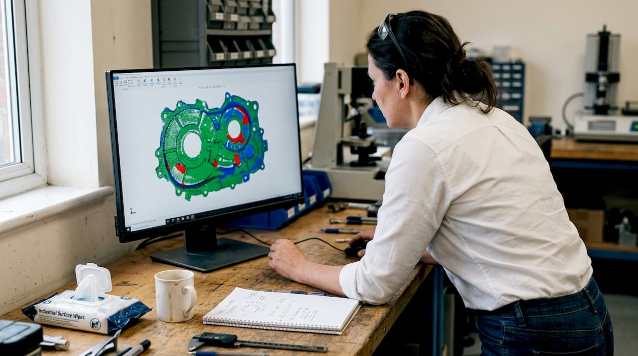
Engineer checks point cloud for scan errors

Noise artifacts show up as scattered points floating away from the actual surface. This happens when ambient light interferes with the scanner or when surface properties confuse the measurement system. Clean up minor noise in post processing software, but severe artifacts require rescanning with better environmental control. Check that your lighting hasn’t changed and that no reflective objects are visible in the scanner’s field of view.

Compare scan results to original CAD models or physical measurements to validate accuracy. Import your point cloud into inspection software and run deviation analysis. Color maps instantly reveal where your scan differs from the reference geometry. Focus on critical dimensions and functional features rather than cosmetic surfaces.

Use quantitative metrics for objective quality assessment:

  • Coverage Factor: Percentage of target surface captured in scan data
  • Point density: Number of measurement points per square millimeter
  • Standard deviation: Variation in measurements across repeated scans
  • Scan Quality Index (SQI): Composite score based on completeness and noise levels
Metric Target Value Acceptable Range
Coverage Factor 98-100% 95% minimum
Point Density 50-100 pts/mm² 30 pts/mm² minimum
Standard Deviation <0.05mm <0.1mm acceptable
SQI Score 90-100 80 minimum

Understand precision limits and expected uncertainty for your scanner class. Uncertainty measurements of 41 microns represent achievable performance with industrial CT and CMM systems, but portable scanners typically operate at 50-150 micron uncertainty. Set realistic expectations based on your equipment capabilities.

Pro Tip: Create a reference artifact that matches your typical part materials and geometry. Scan it regularly to track your system’s performance over time and catch calibration drift before it affects production parts.

“Quantitative verification transforms scanning from guesswork into a controlled measurement process. Metrics give you confidence that your data meets manufacturing requirements.”

Our 3D modeling gallery showcases parts created from verified scan data, demonstrating the quality achievable with rigorous verification protocols.

Applying high quality 3D scans in manufacturing and prototyping

Accurate scan data becomes valuable only when you successfully integrate it into your manufacturing workflow. Real world applications emphasize scan accuracy as critical for functional parts and prototypes that must perform under real conditions. Understanding how to bridge scanning and production maximizes your investment in measurement technology.

Integrate scan data into CAD workflows by importing point clouds or mesh files into your design software. Modern CAD platforms offer tools to fit geometric primitives to scanned surfaces, extract cross sections, and create parametric models from measurement data. This reverse engineering process lets you modify existing parts, create replacement components, or design assemblies that interface with scanned geometry.

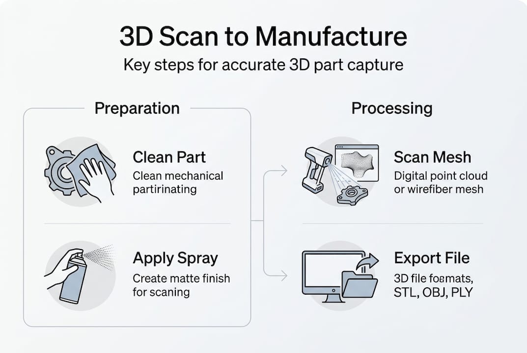
Prepare scan files for 3D printing or CNC manufacturing by converting point clouds to watertight mesh models. Clean up scan artifacts, fill small holes, and smooth surfaces while preserving critical dimensions. Export in formats appropriate for your manufacturing process: STL for 3D printing, STEP for CNC machining, or IGES for injection molding tool paths. Verify that file resolution matches your manufacturing tolerances without creating unnecessarily large datasets.

Infographic showing 3D scan workflow steps

Understand tolerances achievable from scan based models. Your final part accuracy depends on both scan precision and manufacturing process capabilities. A scan with 50 micron uncertainty combined with 3D printing at 100 micron layer height produces parts with approximately 150 micron total variation. Stack these tolerances appropriately when designing assemblies with multiple scanned components.

Benefits of accurate scans extend beyond dimensional correctness:

  • Reduced rework cycles by catching design issues before manufacturing
  • Faster development timelines through parallel scanning and design work
  • Improved communication with manufacturers using verified 3D data
  • Lower prototype costs by minimizing failed builds
  • Better documentation for quality control and inspection

Best practices for scanning to prototype workflow include maintaining a digital thread from initial scan through final production. Document scan parameters, verification results, and any modifications made during CAD processing. This traceability helps you troubleshoot problems and replicate successful processes. Archive raw scan data alongside processed models so you can return to original measurements if needed.

Our 3D printed prototypes service combines accurate scanning with precision manufacturing, delivering functional parts that match your specifications from initial measurement through final production.

Enhance your projects with expert 3D scanning and printing services

Mastering the high quality 3D scan process takes time, specialized equipment, and repeated practice. Many product developers find that partnering with experienced scanning professionals accelerates their projects while ensuring measurement accuracy. Professional services eliminate the learning curve and equipment investment, letting you focus on design and development.

https://cc3dlabs.com

CC 3D Labs delivers high-accuracy scanning integrated with advanced manufacturing capabilities. Our scanning experts handle surface preparation, multi-angle capture, and rigorous verification, providing you with clean, accurate data ready for immediate use. We bridge scanning and production seamlessly, offering 3D printing services that transform your scans into functional prototypes and production parts.

Whether you need 3D scanning services for reverse engineering, quality inspection, or prototype development, our Philadelphia area facility provides fast turnaround with engineering grade accuracy. We support projects from single prototype scans to batch production scanning, with options for local pickup or international shipping. Get a free online estimate and discover how professional scanning accelerates your development timeline while reducing costs.

Our 3D printed prototypes and repair parts service completes the workflow from scan to finished component, ensuring your parts meet functional requirements and manufacturing tolerances.

Frequently asked questions

What surfaces are hardest to scan and how to handle them?

Reflective metallic surfaces, glossy plastics, and black rubber materials present the greatest scanning challenges. Shiny and dark surfaces cause data loss by scattering or absorbing the scanner’s projected light patterns. Apply temporary scanning spray to create a matte coating that improves light return. Use adhesive reference markers on highly reflective areas to give the scanner tracking points. For transparent materials, consider using colored dyes or coatings that wash off after scanning.

How to verify the accuracy of a 3D scan?

Compare your scan data to original CAD models using deviation analysis software that generates color coded error maps. Measure critical dimensions on the physical part with calipers or micrometers, then verify those same features in your scan data. Empirical studies measure uncertainty around 41 microns for industrial scanning systems, providing a benchmark for expected precision. Use quantitative metrics like Coverage Factor and Scan Quality Index for objective assessment rather than relying on visual inspection alone.

What scanner type is best for shop floor use versus lab accuracy?

Portable handheld scanners offer flexibility for shop floor measurement but trade some accuracy for usability, typically achieving 50-150 micron precision. Stationary structured light or laser scanners deliver laboratory grade accuracy below 50 microns but require controlled environments and fixed setups. Select scanners using quantitative metrics that match your tolerance requirements. For functional prototypes, portable scanners often provide sufficient accuracy. For metrology and quality inspection, invest in stationary systems with verified uncertainty specifications.

How long does a typical high quality 3D scan take?

Scanning time varies dramatically based on part size, complexity, and required accuracy. Simple parts under 6 inches may scan in 15-30 minutes including setup and verification. Complex assemblies with intricate features can require 2-4 hours for complete multi-angle coverage. Factor in additional time for surface preparation, calibration, and post-processing. Professional scanning services optimize these workflows, often completing projects faster than in-house scanning due to experience and specialized equipment.