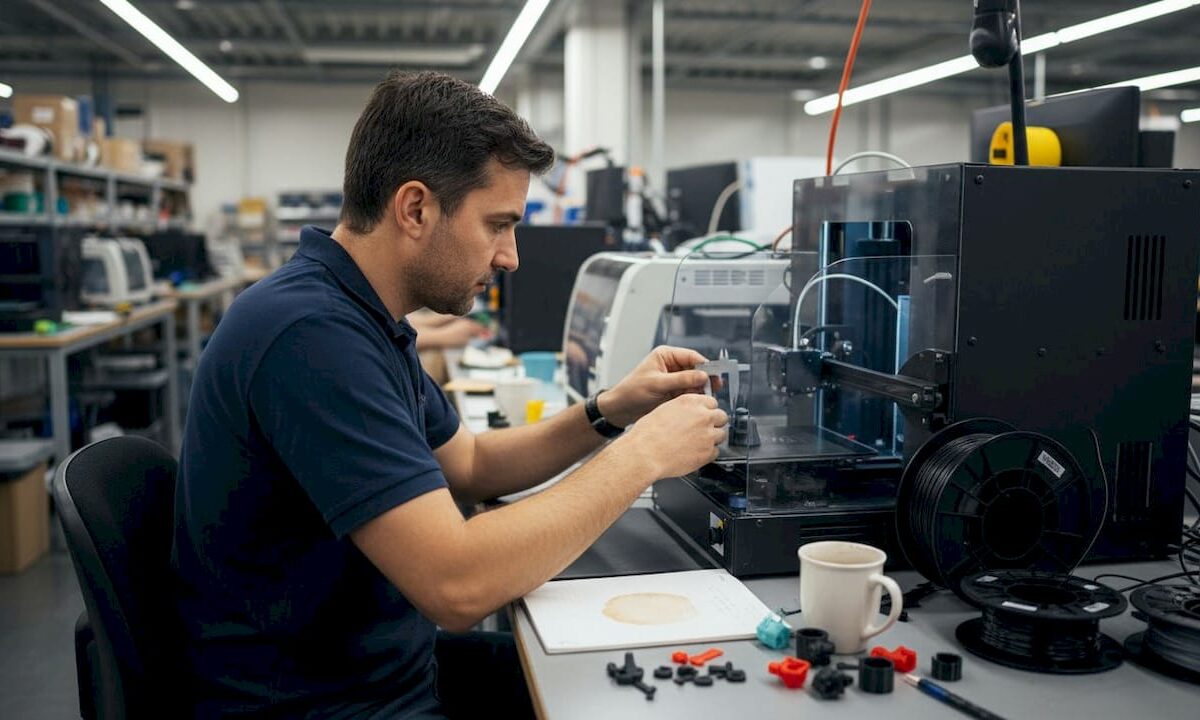
Engineer reviewing 3D CAD model in office

Top ways to validate 3D designs for reliable manufacturing


TL;DR:

  • Sending a flawed design file to production can lead to costly rework, missed deadlines, and scrapped parts.
  • Thorough 3D design validation, including geometry checks and reliable simulations, is essential before manufacturing begins.

Sending a flawed design file to production is one of the most expensive mistakes a product developer can make. A single overlooked wall thickness issue, a misapplied boundary condition in your simulation, or an ignored build orientation effect can mean scrapped parts, missed deadlines, and rework costs that eat straight into your project budget. Thorough 3D design validation is not a luxury step you add when time allows. It is the structured process that stands between a confident manufacturing run and a costly surprise. This article breaks down the most reliable methods to validate your designs before a single layer is printed.

Table of Contents

Key Takeaways

Point Details
Check early in CAD Surface deviation and wall thickness checks in CAD catch errors before prototyping.
Validate simulations rigorously Use mesh convergence, realistic materials, and compare with tests to ensure credible results.
Consider AM process effects Allow for part orientation and build location, as they directly impact final part accuracy.
Compare validation methods Use a mix of geometry, simulation, and manufacturing-focused checks for best outcomes.
Physical measurement trumps theory Always confirm with real-world testing before committing to mass production.

Check essential geometry and manufacturability constraints

With validation’s value established, let’s start at the CAD level, the foundation for reliable prototypes and parts.

Most design failures originate in the CAD file, not on the production floor. When you export a model that has non-manifold geometry, tiny gaps in surface meshes, or features too small for your target process to resolve, you are essentially shipping a problem downstream and paying someone else to find it. The good news is that modern CAD platforms give you tools to catch these issues before they travel anywhere.

Geometry validation early means checking surface deviation from reference geometry, confirming minimum wall thickness, and identifying features that the manufacturing process physically cannot produce. This applies to both subtractive machining and additive processes, but the specific thresholds vary. For FDM printing, a wall thinner than one nozzle diameter simply will not print. For SLS, fine lattice features below roughly 0.8 mm may fuse or collapse depending on the material and machine.

Key manufacturability constraints to check before you finalize any design:

  • Minimum wall thickness: Confirm walls meet your process’s minimum. For most FDM machines using a 0.4 mm nozzle, the minimum is roughly 1.2 mm for structural walls.
  • Unsupported overhangs: Overhangs beyond 45 degrees in FDM need support material. Designing to reduce support dependency saves post-processing time and surface quality issues.
  • Sharp interior corners: Stress concentrates at sharp internal corners. Radius them to at least half the wall thickness for functional load-bearing parts.
  • Detail resolution: Features smaller than the process resolution will not reproduce accurately. Embossed text, snap features, and thread starts are common failure points.
  • Mesh integrity: Export your STL or 3MF file and run it through a mesh repair check. Holes, inverted normals, and non-manifold edges cause slice errors that silently degrade part quality.

If you are working on parts where dimensional precision matters, review our guide to designing reliable 3D prints before finalizing your CAD. And if measurement validation is part of your workflow, the 3D scanning checklist walks you through exactly what to capture from physical parts for comparison.

Pro Tip: Set up automated geometry health checks in your CAD environment or through a dedicated add-on. Running these checks every time you export a file takes less than a minute and catches issues that manual review misses during long sessions.

For teams pursuing manufacturing-grade 3D printing, geometry validation is not optional. It is the baseline that every downstream step depends on.

Apply rigorous simulation validation steps

Geometric checks are necessary, but design validation reaches a new level with reliable simulation. Here’s how to ensure your virtual results reflect real-world performance.
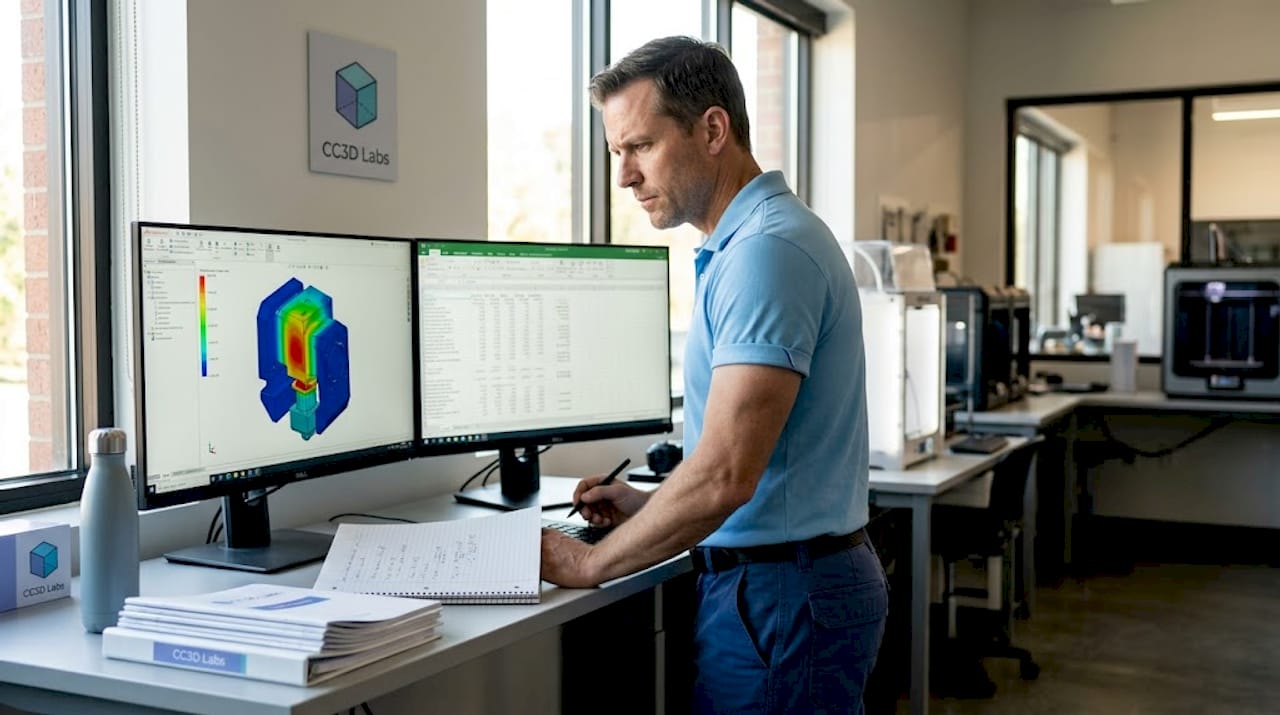
Technician reviewing simulation results for 3D part

Running a finite element analysis (FEA) or computational fluid dynamics (CFD) simulation is only useful if the results are trustworthy. Many development teams make the mistake of treating simulation output as ground truth without verifying that the model itself is credible. A simulation built on incorrect boundary conditions or an under-resolved mesh will give you precise numbers that are completely wrong.

FEA credibility steps include mesh convergence studies, sensitivity analysis, realistic boundary conditions, accurate material properties, and comparison with experimental or analytical data. Follow this numbered sequence for every critical simulation run:

  1. Define realistic boundary conditions. Model how the part is actually constrained and loaded in service. A fixed-wall assumption when the real mount allows slight rotation will overestimate stiffness by a significant margin.
  2. Assign accurate material properties. Use measured data for the specific material grade and print orientation you are targeting. Published datasheet values are starting points, not substitutes for validated material cards.
  3. Run a mesh convergence study. Refine the mesh in stages and track your key output (peak stress, deflection, etc.). When refining the mesh further changes results by less than 5%, you have reached convergence.
  4. Perform sensitivity analysis. Vary your key inputs by a realistic uncertainty range. If small changes in your material inputs swing the predicted stress dramatically, you need better material data before trusting the result.
  5. Compare to a benchmark. Where possible, validate at least one simulation case against a physical test, a hand calculation, or a well-documented analytical solution.

For CFD work, the validation logic is similar but the pre-flight checks differ. CFD boundary layer resolution requires verifying the correct flow regime through Reynolds and Mach number checks, applying consistent and physically realistic boundary conditions, and resolving the near-wall region with appropriate boundary layer meshing. Getting the y+ value wrong in a turbulent flow case can produce drag and heat transfer predictions that are far off from measured values.

“Simulation-to-reality confidence is earned, not assumed. Every result needs a credibility trail, and that trail starts with the inputs.”

Pro Tip: Before signing off on any design validation package, physically benchmark at least one simulation case. Print a test part, measure it, load it to failure or measure pressure drop, and compare to your model. One confirmed data point is worth far more than ten unverified simulation runs.

For a process-level view of how simulation fits into production prep, check our step-by-step 3D printing guide and our overview of simulation validation best practices tied to physical part measurement.

Account for additive manufacturing-specific accuracy factors

After simulation, consider how manufacturing realities introduce new sources of variation, especially in additive processes.

Here is something many engineers underestimate: a perfectly designed CAD file and a validated simulation do not guarantee dimensional accuracy in the final printed part. Additive manufacturing introduces process-specific variation that exists entirely outside of your digital model. Build orientation, thermal gradients during the print cycle, and where the part sits inside the build chamber all affect the dimensions you will measure on the finished part.

Research on PA12 SLS parts shows that build orientation and chamber position measurably affect dimensional outcomes in ways that nominal CAD dimensions cannot predict. Parts built vertically may exhibit different shrinkage behavior compared to parts built horizontally, and parts at the chamber periphery often differ from those at the center due to thermal variation during the sintering cycle.

Practical methods for measuring and compensating for these effects:

  • Print calibration test artifacts. Before committing to a full production run, print a calibration coupon that includes representative features from your design: bosses, holes, flat spans, and slots. Measure these with calipers or, for critical parts, a coordinate measuring machine (CMM) or 3D scanner.
  • Document orientation-dependent deviation. Keep a log of how your machine and material combination behaves at different orientations. This becomes a design correction database over time.
  • Apply dimensional compensation offsets. If your CAD hole is consistently undersized by 0.15 mm after printing, adjust the nominal dimension to compensate. This is standard practice in professional AM workflows.
  • Account for anisotropy in functional parts. Mechanical properties vary by build axis in FDM and SLS. A part loaded along the Z axis (layer stacking direction) will be weaker than one loaded in XY. Design and validate accordingly.
Feature type Build orientation effect Chamber position effect Typical deviation range
Circular holes Moderate (XY vs. Z) Low to moderate 0.05 to 0.25 mm
Flat spans Low Moderate (center vs. edge) 0.03 to 0.15 mm
Vertical walls High Low 0.10 to 0.30 mm
Thin features High Moderate 0.10 to 0.40 mm

For teams focused on ensuring 3D print accuracy, tracking these variables is not optional. It is the difference between parts that fit and parts that need rework. Our low-volume 3D printing tips cover how to integrate these checks into short-run production workflows without slowing your schedule.

Summary table: Comparing key 3D design validation methods

With the main validation methods explained, a side-by-side comparison clarifies which approaches to prioritize.

Validation method Speed Reliability Required tools Best project stage
Geometry and manufacturability checks Very fast High for CAD-level issues CAD software, mesh repair tools Early design, pre-export
FEA simulation Moderate High if properly credentialed FEA solver, material data Detailed design, pre-prototype
CFD simulation Slow to moderate High with correct setup CFD solver, meshing tools Detailed design, thermal/flow parts
AM-specific dimensional validation Moderate Very high for process accuracy Calipers, CMM, 3D scanner Pre-production, first article
Physical benchmark testing Slow Definitive Test equipment, prototype parts Final design sign-off

The key insight from this comparison is that no single method covers all failure modes. Geometry checks are fast but tell you nothing about structural performance. FEA tells you about stress but not about how your machine will place those features in real space. Physical benchmarking is the most reliable but the slowest and most expensive. The winning strategy is to use these methods in sequence, using each one to reduce the risk that reaches the next stage.

Perspective: Why real-world validation always beats theoretical checks

Here is the uncomfortable reality that experienced product engineers know but rarely put in writing: digital validation is a filter, not a guarantee. CAD geometry checks and even well-credentialed simulations operate on idealized models. They assume uniform material properties, perfectly constrained geometry, and conditions that match whatever you entered into the model. The physical world does not honor those assumptions.

We have seen parts pass every simulation check, print cleanly, and then fail in assembly because a surface finish tolerance was tighter than the process could consistently hold. We have seen FEA results predict deflection within 2% of measured values, and then watched the same design crack at a feature that the mesh resolution had quietly smoothed over. These are not rare edge cases. They are predictable consequences of relying too heavily on theoretical validation.

The teams that consistently avoid manufacturing surprises do something deliberate: they treat digital checks as risk reduction tools and physical testing as risk confirmation tools. They run geometry checks and simulation early because it is cheap to catch errors at that stage. But they never skip the physical benchmark, even when the simulation looks clean. That benchmark might be a single printed part measured with a 3D scanner, or a simple load test on a coupon. The point is to introduce real-world data before the design is locked.

“Every model is a simplification. The question is whether your simplification preserved the physics that matter.”

The hidden gap between theory and practice is widest in additive manufacturing because the process itself introduces so many uncontrolled variables: ambient temperature, humidity, batch variation in powder or filament, and cumulative machine wear. A design validated purely in CAD and simulation may perform perfectly in batch one and show drift in batch three. Integrating physical measurement into your validation loop, even periodically, catches this drift before it becomes a field problem.

Our perspective, built from working with product developers across industries, is this: invest in digital tools, use simulation rigorously, but never mistake sophistication for certainty. The guide to manufacturing-grade 3D printing we put together reflects this philosophy. Physical results close the loop that theory opens.

Get expert support for validating your 3D designs

Validation is most valuable when it combines structured digital checks with hands-on manufacturing experience. At CC 3D Labs, near Philadelphia, we work with product developers and engineers at every stage of the design-to-production cycle, from reviewing CAD files for printability to producing first-article parts for dimensional inspection.

https://cc3dlabs.com

Our 3D printing services include design review, rapid prototyping, and professional handheld 3D scanning (accuracy to ~0.1 mm) that supports real-world dimensional validation. If you need to move from a validated simulation to a physical part fast, our on-demand prototypes are produced with tight tolerances and full traceability. For teams working through material selection and process setup, the custom filament printing guide covers exactly what you need to know before your first production run. Reach out for a free estimate and let’s put your design through its paces before it reaches the production floor.

Frequently asked questions

What is the first step in validating a 3D design?

Start with geometry and manufacturability checks in your CAD software to identify surface deviations, thin walls, and feature resolution issues before prototyping. This is the fastest and cheapest place to catch errors.

Why is simulation validation important before physical prototyping?

Credible simulation, built with mesh convergence and realistic inputs, gives you confidence that your design will perform as intended and avoids rework costs from unexpected structural or thermal failures.

How can I improve the accuracy of 3D printed parts?

Build orientation and chamber position both influence final part dimensions in additive manufacturing, so accounting for these variables and applying measured compensation offsets produces more accurate outcomes.

What makes a simulation “credible” for design validation?

A credible simulation includes mesh convergence, sensitivity analysis, accurate material properties, and at least one comparison to experimental data or a verified analytical solution before it can be used for design sign-off.
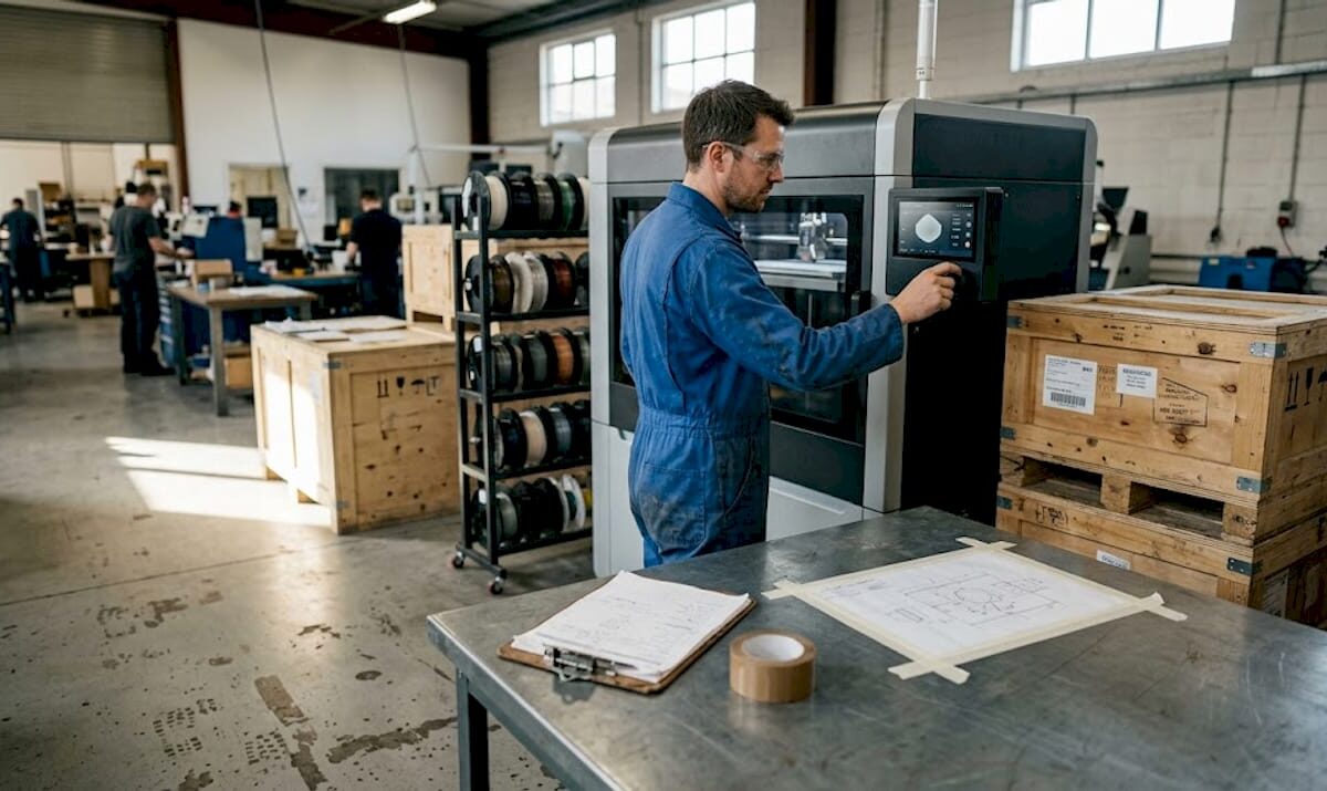
Technician adjusts industrial 3D printer on factory floor

Manufacturing-grade 3D printing: a guide for production


TL;DR:

  • Manufacturing-grade 3D printers are designed for production with high repeatability and process control.
  • Seven ISO/ASTM recognized AM processes match specific applications, materials, and accuracy needs.
  • Successful industrial use depends on robust process validation and quality management, not just machine specs.

Most engineers assume any 3D printer can handle production work if the settings are dialed in correctly. That assumption costs time, money, and credibility. Manufacturing-grade 3D printing operates under an entirely different set of requirements, from material traceability and process repeatability to factory-floor integration and in-process quality monitoring. This guide breaks down exactly what separates industrial additive manufacturing (AM) from desktop and prototyping systems, covers the seven ISO/ASTM-recognized AM processes, compares equipment tiers side by side, and connects those facts to real-world applications in aerospace, medical, automotive, and electronics. By the end, you will know how to evaluate systems and make confident technology decisions for your next project.

Table of Contents

Key Takeaways

Point Details
Not all 3D printers are alike Manufacturing-grade 3D printers deliver high reliability, precision, and repeatability that desktop models can’t match.
Seven AM processes matter Understanding ISO/ASTM methods unlocks the right manufacturing-grade solution for your application.
Accuracy and monitoring are crucial Production-grade systems ensure process control for functional, end-use parts every time.
Choose methods for the outcome Selecting the right AM technology accelerates prototyping and low-volume production with minimal compromises.

Defining manufacturing-grade 3D printing

Not every machine that melts filament or cures resin qualifies as a manufacturing-grade system. The distinction matters enormously when you are designing parts that must pass validation, meet regulatory standards, or ship inside a finished product.

Manufacturing-grade 3D printing refers to industrial AM systems designed for production use, emphasizing repeatability, throughput, controlled materials, in-process monitoring, and auxiliary equipment for factory integration. That definition draws a hard line between systems built to produce consistent, documented output and systems built to make one-off prints quickly.

So what does that actually look like in practice? Here are the core elements that define a manufacturing-grade system:

  • Repeatability: Part dimensions and mechanical properties remain consistent across a full production batch and across multiple build cycles over time.
  • Throughput: Systems are designed to run continuously or at high duty cycles without compromising output quality.
  • Controlled material handling: Feedstocks are qualified, certified, and handled under strict conditions to prevent moisture absorption, contamination, or property drift.
  • In-process monitoring: Sensors, cameras, and closed-loop feedback systems catch deviations during the build, not after the part comes off the machine.
  • Factory integration: Industrial AM equipment connects to ERP systems, quality management software, and downstream automation for traceability from raw material to finished part.

“Manufacturing-grade 3D printing is not about a single machine capability, it is about the entire production system operating predictably, documentably, and repeatably within a quality-controlled environment.”

For product developers, understanding 3D printing terminology is the first step toward making informed decisions about which systems belong in a manufacturing workflow. A printer that works brilliantly for a proof-of-concept prototype may introduce unacceptable variance the moment you scale to 500 units. That gap between prototyping capability and production reliability is where projects stall and where manufacturing-grade systems deliver their real value.

Key methodologies: Seven core AM processes

Having defined what makes a system manufacturing-grade, let’s look at the main additive manufacturing methods recognized by standards organizations.

ISO and ASTM jointly classify AM into seven process categories, each with distinct material compatibility, accuracy ranges, and production suitability. Understanding these categories helps you match the process to your part requirements rather than defaulting to whatever technology you have access to.

  1. Powder Bed Fusion (PBF): Includes SLS, HP Multi Jet Fusion (MJF), and DMLS. A laser or energy source selectively fuses powdered material layer by layer. This is the dominant method for industrial polymer and metal production.
  2. Binder Jetting: A liquid binding agent selectively joins powder particles. No heat during the build, which reduces warping. Used for metal, sand, and ceramic parts.
  3. Directed Energy Deposition (DED): Melts material as it is deposited, typically for large metal parts or repair applications. Common in aerospace and defense.
  4. Material Extrusion (industrial FDM): The industrial version of desktop FDM uses high-temperature materials like ULTEM and PEEK in enclosed, thermally controlled chambers.
  5. Material Jetting: Droplets of photopolymer are jetted and cured layer by layer, delivering extremely fine detail and multi-material capability.
  6. Sheet Lamination: Layers of material (metal foil, paper, or plastic) are bonded and cut to shape. Used in specialized tooling applications.
  7. Vat Photopolymerization (SLA/DLP): A UV light source cures liquid resin, producing high-surface-quality parts often used in dental, medical, and consumer product industries.
Process Primary materials Typical accuracy Best application
Powder Bed Fusion Polymers, metals ±0.1 to ±0.3 mm Low-volume production parts
Binder Jetting Metal, ceramic, sand ±0.2 to ±0.5 mm Complex metal geometries
DED Metals ±0.25 to ±1.0 mm Large parts, repair
Material Extrusion Engineering polymers ±0.1 to ±0.5 mm Functional prototypes
Material Jetting Photopolymers ±0.05 to ±0.1 mm High-detail, multi-material
Vat Photopolymerization Resins ±0.05 to ±0.15 mm Surface-critical parts

For polymer production, powder bed fusion technologies like MJF and SLS are preferred for low-volume manufacturing because they produce isotropic parts without support structures, which reduces post-processing time and eliminates weak points common in support-dependent processes.

Pro Tip: When choosing the right process for a production application, prioritize isotropy and material qualification over surface finish. A slightly rougher surface is far easier to fix than unpredictable mechanical properties.

For developers exploring AM process terms for the first time, the takeaway is simple: process selection is a design decision, not an afterthought.

Manufacturing-grade vs. prototyping and consumer printers

With the methodologies in mind, it’s essential to see how industrial printers differ from more familiar kinds.

The gap between a consumer desktop printer and a manufacturing-grade industrial system is not just price. It is a fundamental difference in engineering purpose, process control, and output consistency.

Engineer compares desktop and industrial 3D printers

Feature Consumer/desktop Prototyping grade Manufacturing grade
Dimensional accuracy ±0.5 to ±2.0 mm ±0.2 to ±0.5 mm ±0.089 to ±0.2 mm
Repeatability Low, batch variance common Moderate High, statistically validated
Material qualification Open/unqualified Limited qualified options Certified, traceable feedstocks
In-process monitoring None Basic Full closed-loop feedback
Build volume Small Medium Large, multi-unit batches
Factory integration None Minimal ERP, MES, QMS compatible

Manufacturing-grade systems achieve tight tolerances like the ±0.089mm accuracy documented on the Stratasys F900, with high yield rates across production batches, while consumer printers show significant dimensional variance from print to print.

Here is where engineers most often run into trouble:

  • Assuming prototyping accuracy translates to production: A printer that hits ±0.3mm on a single prototype may drift to ±0.8mm across a 200-unit batch because no process controls are in place.
  • Ignoring material traceability: For regulated industries, you need to document the exact material lot, print parameters, and machine state for every part. Consumer printers cannot support this.
  • Underestimating post-processing variance: Without controlled cooling, chamber temperature, and humidity, post-processing can introduce more variation than the print itself.

Understanding 3D printing quality from a systems perspective, not just a machine spec perspective, is what separates engineers who consistently deliver reliable parts from those who keep chasing print failures. If your project involves functional assemblies or end-use components, filament prototyping on a consumer machine may work for early validation, but it should never be the final production solution.

Pro Tip: Always ask your 3D printing service provider for documented Cpk values or repeatability data from actual production runs, not just machine spec sheets. That number tells you far more than advertised accuracy claims.

The importance of print accuracy cannot be overstated when you move from design exploration into production validation. Every decimal point on a tolerance spec represents real-world fit, function, and safety margin.

Applications and advantages of manufacturing-grade 3D printing

Understanding what makes manufacturing-grade equipment different, let’s explore the real-world impact and industrial benefits.

Manufacturing-grade AM systems are not a niche solution. They serve as core production tools in some of the most demanding industries on the planet.

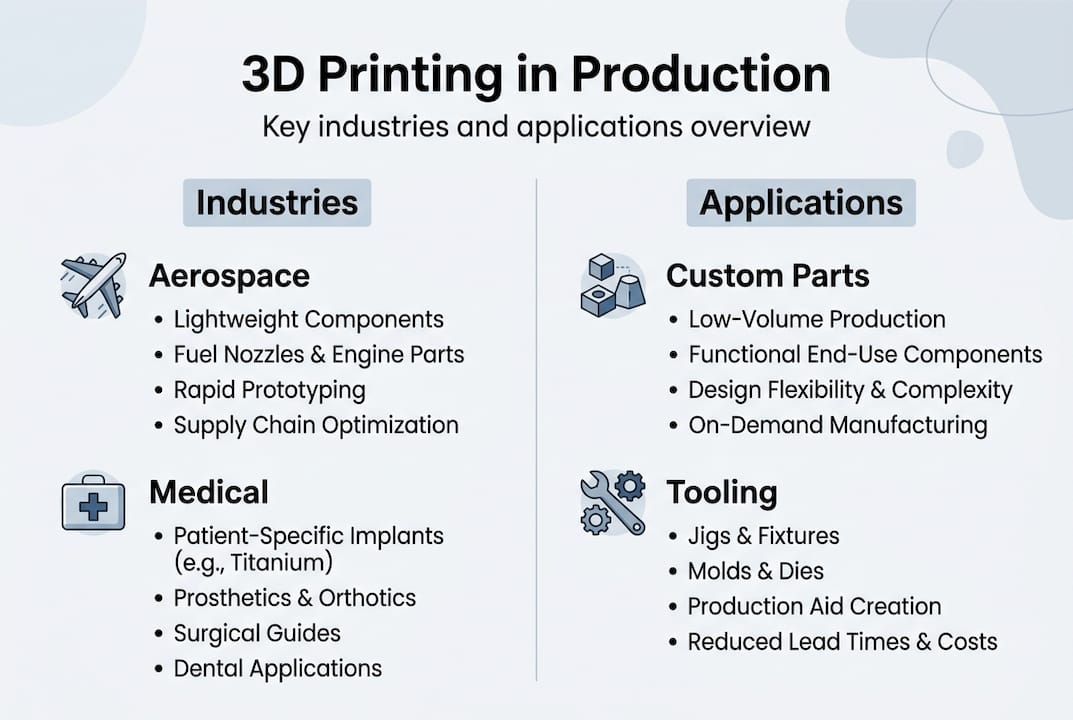
Aerospace and defense use AM for lightweight structural components, ducting, brackets, and heat exchangers. Parts that previously required complex machining or multi-piece assemblies can now be produced as single, optimized geometries.

Medical device manufacturers rely on AM for patient-specific implants, surgical guides, and custom orthotics. The combination of geometric freedom and material traceability is essential for regulatory compliance in this sector.

Automotive teams use industrial AM for end-of-arm tooling, jigs, fixtures, and increasingly for low-volume production parts in electric vehicles and specialty vehicles where traditional tooling costs cannot be justified.

Infographic of 3D printing applications by industry

Electronics and consumer products benefit from AM’s ability to produce complex enclosures, custom connectors, and thermal management components in engineering-grade polymers.

Key advantages that matter for product developers:

  • Geometric freedom: You can print internal channels, lattice structures, and organic geometries that are impossible to machine or mold at any cost.
  • Speed to market: Industrial AM eliminates tooling lead times. Parts that would take 12 to 16 weeks through injection molding can ship in days.
  • Part traceability: Every build is logged with material lot, machine parameters, and operator data, creating a complete quality record.
  • Scalability: Run 5 units or 5,000 units from the same digital file with no retooling cost.

Statistic callout: Powder bed fusion systems like HP MJF produce layers as fine as 80μm while SLS operates around 120μm, delivering isotropic mechanical properties that make these parts suitable for functional, end-use manufacturing without secondary reinforcement.

For a clear view of types of parts possible with industrial AM, the range is broader than most developers expect. And when durability matters, selecting best materials for durability is as critical as selecting the right process.

Our perspective: What engineers miss about manufacturing-grade 3D printing

Most articles about manufacturing-grade 3D printing focus on machine specs, material options, and accuracy numbers. Those things matter, but they miss the deeper issue that experienced teams consistently run into.

The real failure point is almost never the printer. It is the lack of process validation, documentation standards, and quality system integration surrounding the printer. Engineers who move from consumer or mid-tier prototyping equipment to industrial AM often expect a plug-and-play upgrade. What they get instead is a system that demands the same rigor as any other regulated manufacturing process.

Material qualification, environmental controls, build parameter version control, operator training, and output inspection protocols are not optional extras on a manufacturing-grade setup. They are the system. The printer is just one component of it.

Conventional wisdom says, “get a better printer and get better parts.” The truth is, a well-run mid-tier system with disciplined process controls will consistently outperform a premium machine operated without them. Choosing correctly means choosing the right process and the right operational framework around it. Manufacturing-grade is about outcome assurance, not machine capability alone.

Get expert help with manufacturing-grade 3D printing

If you are ready to move your project from concept to production-quality output, the next step is working with a partner who understands both the technology and the engineering requirements behind it.

https://cc3dlabs.com

At CC 3D Labs, we provide manufacturing-grade 3D printing services for product developers and engineers who need reliable, documented results, not just fast prints. Whether you need functional prototypes, low-volume production runs, or on-demand custom parts, we bring process expertise and quality focus to every order. Explore parts you can print with industrial-grade filament systems and request a free estimate to get your project moving with confidence.

Frequently asked questions

What makes a 3D printer manufacturing-grade?

Manufacturing-grade 3D printers are designed for production environments, offering high repeatability, controlled material usage, in-process monitoring, and factory integration. They are built to document and validate every aspect of the production process, not just produce individual parts.

Which 3D printing method is best for low-volume polymer production?

Powder Bed Fusion technologies like SLS and HP Multi Jet Fusion are preferred for low-volume polymer manufacturing because they produce isotropic parts without support structures, which improves consistency and reduces post-processing.

Can manufacturing-grade 3D printers be used for end-use functional parts?

Yes. Systems like HP MJF and SLS produce isotropic end-use parts with fine layer resolution and material traceability, making them fully suitable for functional, production-intent components in aerospace, medical, and automotive applications.

Why is print accuracy important in manufacturing-grade systems?

Precise, validated accuracy ensures that parts meet dimensional tolerances consistently across an entire batch. The Stratasys F900 achieves ±0.089mm accuracy at a 95% yield rate, which is the kind of documented repeatability that production engineering actually requires.

Technician inspects batch 3D printed parts

Batch 3D Printing: A Practical How-To Guide for 2026


TL;DR:

  • 3D printing is cost-effective for batch sizes up to 500 units, especially for complex geometries.
  • Preparing detailed design verification, proper material selection, and meticulous post-processing are essential for quality.
  • Scaling requires validation, central management, and risk mitigation through smaller sub-runs and redundancy.

Traditional manufacturing hits a wall when you need 50, 200, or 500 parts fast. Tooling costs for injection molding can exceed tens of thousands of dollars before a single part ships, and CNC machining queues stretch weeks when you need agility. 3D printing flips that equation, letting you run functional batches without custom tooling, long lead times, or minimum order commitments. This guide walks you through every stage of batch production with 3D printing, from early design decisions to post-processing and scaling, so you can move faster, waste less, and produce parts that actually perform.

Table of Contents

Key Takeaways

Point Details
Best for small to medium runs 3D printing shines in batch production for units below 1000, avoiding costly tooling.
Preparation is critical Successful batches depend on careful design, material choice, and spacing strategies.
SLS and MJF for durability These methods offer superior consistency and strength over FDM, making them ideal for functional parts.
Scale with caution Split large jobs into safer batches and document processes for better control and repeatability.

Understanding batch production in 3D printing

Batch production means manufacturing a defined quantity of parts in one or more coordinated print runs, rather than printing one-off or running continuous mass production. In the 3D printing context, a batch can be as small as 10 units or as large as several hundred, all produced with consistent settings, materials, and quality checks.

The question most engineers face is: when does 3D printing beat traditional manufacturing for batch work? The answer depends on volume, complexity, and tooling cost. 3D printing is cost-effective under 500 units, especially for complex geometries that would require expensive molds or multi-axis CNC fixturing. Above 1,000 units, injection molding typically wins on per-part cost, but you lose the flexibility to iterate designs mid-run.

For low-volume manufacturing tips that keep costs under control, the key advantage of 3D printing is eliminating setup costs entirely. No mold, no jig, no fixture. You change a file and reprint.

When 3D printing batch production makes sense:

  • Runs of 10 to 500 units with design iteration expected
  • Complex internal geometries that molds cannot produce
  • Tight launch timelines with no room for tooling lead times
  • Custom or personalized variants within the same batch
  • Bridge production while waiting for injection mold tooling

Here is a quick comparison to frame your decision:

Factor 3D printing Injection molding CNC machining
Setup cost Near zero $5,000 to $50,000+ Medium to high
Best volume Under 500 units Over 1,000 units 1 to 200 units
Design changes Instant file update Mold rework required Re-program needed
Geometry complexity Excellent Limited by draft angles Limited by tool access
Lead time Hours to days Weeks to months Days to weeks

Hybrid workflows, combining additive manufacturing with light CNC finishing, often deliver the best results for functional batches needing tight tolerances. Knowing which 3D printing type to choose for your part requirements is the first real decision.

Engineer measuring 3D printed part at bench

Mapping out your batch: Preparation essentials

Understanding the benefits is only useful if you prepare correctly. Here’s what you need for a smooth batch production run.

Before you start printing, your design files and production plan need to be solid. A single upstream error, like a wall thickness below the printer’s reliable minimum, can ruin an entire tray of parts. Designing reliable 3D prints starts with checking tolerances, adding consistent wall thicknesses, and minimizing overhangs that require dense support structures.

Pre-batch preparation checklist:

  • Verify all STL or 3MF files are watertight with no mesh errors
  • Set tolerances to account for your material’s shrinkage rate
  • Orient parts to minimize support material and maximize layer strength
  • Choose material based on mechanical, thermal, and surface finish requirements
  • Confirm build volume fits your batch without overcrowding
  • Test one or two parts before committing the full batch

Material selection is often underestimated. PLA works for display prototypes but fails under heat or load. PETG balances ease of printing with decent mechanical properties. Nylon and PA12 powders suit functional end-use parts. Your post-processing plan also influences material choice, since some materials sand, dye, or machine better than others.

For FDM batch runs, sequential printing over simultaneous is more reliable, especially on multi-nozzle or single-head machines. Keep 5 to 10mm spacing between parts, enable Z-hop at 0.2 to 0.4mm to avoid knocking parts over, and turn on combing to minimize stringing across the build plate. For powder-bed processes like SLS, the powder acts as a self-supporting medium, so you can stack and nest parts freely in the Z direction.

Setting FDM batch SLS/MJF batch
Part spacing 5 to 10mm 2 to 5mm
Support strategy Minimized but required Not required
Z-hop 0.2 to 0.4mm Not applicable
Nesting 2D build plate Full 3D volume

If you use 3D scanning to verify existing parts or reverse-engineer components, integrating high quality 3D scan data into your pre-production workflow reduces dimensional errors before the first layer prints.

Pro Tip: Design every part in a batch to share the same orientation on the build plate. Consistent orientation means consistent layer lines, consistent strength, and consistent surface finish across every unit.

Executing the batch production process: Step-by-step guide

Prepping your batch is only half the equation. Now, let’s walk through a reliable execution plan.

  1. Slice and nest your files. Use your slicer’s auto-arrange or manual layout to maximize density without crowding. Review the 3D preview for collisions or thin unsupported sections.
  2. Validate machine state. Check bed adhesion surfaces, nozzle condition, filament moisture content for FDM, or powder age for SLS/MJF. A contaminated bed ruins the entire tray.
  3. Run a single-unit test print. Before committing 200 parts, confirm one unit meets dimensional and visual specs. This step saves hours.
  4. Start the batch and monitor early layers. The first three to five layers predict 90% of batch failures. Stay close or use a camera feed to catch adhesion issues early.
  5. Log runtime parameters. Record temperature, humidity, print speed, and any deviations. This data is your diagnostic tool for the next run.
  6. Handle mid-run adjustments carefully. Some slicers and firmware allow live flow rate or temperature tweaks. If you adjust, document it immediately.
  7. Remove and label each batch tray. Traceability matters. Label each tray with date, material lot, and settings version before post-processing begins.

“MJF PA12 tensile strength reaches approximately 46 MPa and withstands 100,000 cycles with under 16% stiffness loss, while SLS offers better batch-to-batch reproducibility. FDM remains limited by layer anisotropy and delamination risk for functional batch parts.”

For teams printing quality prototypes alongside functional parts, keeping separate print queues by material and purpose prevents cross-contamination of settings and priorities.

Pro Tip: Log every print run in a simple spreadsheet: date, machine, material lot, settings file version, and any anomalies. When a defect appears in batch 47, you will know exactly what changed from batch 46.

For teams scaling to print farm operations, 3D printing on demand with distributed printers requires centralized file management and consistent firmware versions across all machines to avoid output variation.

Post-processing and quality verification: What to check

You’ve completed your batch run, but production isn’t finished until you ensure every part meets your standard.

Post-processing is where batch efficiency either compounds or collapses. Rush it, and defects slip into the supply chain. Over-engineer it, and you lose the cost advantage of additive manufacturing entirely. The goal is a structured, repeatable QA process scaled to your batch size and part function.

Core post-processing steps by part type:

  • Support removal: Remove carefully with flush cutters or media blasting for SLS/MJF parts. Inspect support interfaces for surface damage.
  • Surface finishing: Sand, bead blast, or vapor smooth depending on cosmetic requirements and material.
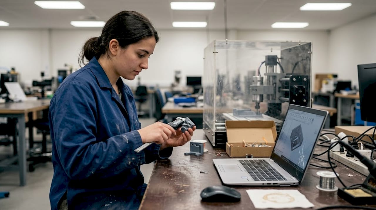
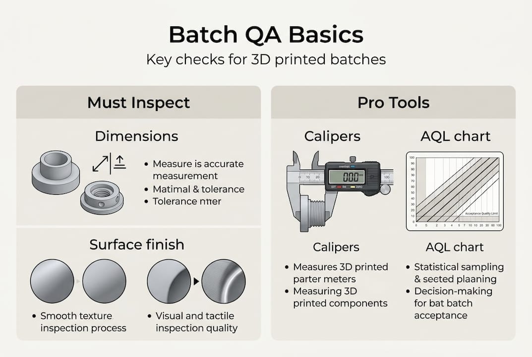
  • Dimensional check: Measure critical features with calipers, CMM, or go/no-go gauges. Focus on mating surfaces, bores, and thread engagement zones.
  • Mechanical inspection: Flex-test clips, torque-test fastener points, or pull-test adhesive joints where functional performance is critical.
  • Cosmetic review: Check for layer delamination, warping, color inconsistency, or surface voids under diffuse lighting.

For production batches of 300 to 800 units in industrial device applications, MJF suits mid-volume functional runs while SLS delivers tighter batch-to-batch reproducibility. FDM is a real risk for parts that see mechanical stress or cyclic loading.

Sampling strategy matters. You do not need to inspect every unit in a 500-part batch. Use AQL (Acceptable Quality Level) sampling tables to select a statistically valid sample size. For critical functional parts, inspect 100%.

Infographic showing batch 3D print QA basics

Printer type Typical post-processing QA priority
FDM Support removal, sanding Delamination, warping
SLS Powder removal, bead blast Dimensional accuracy
MJF Powder removal, dyeing Surface consistency
Resin UV cure, support removal Brittleness, warping

For insight into functional part fabrication requirements across different industries, matching your QA process to the part’s end use is the fastest way to keep costs reasonable without cutting corners.

Scaling up and optimizing your batch production workflow

After validating one batch, you may need to ramp up production. Here’s how to scale efficiently without sacrificing quality.

  1. Validate before scaling. Run two or three small batches with full QA before increasing volume. Undetected issues multiply fast at scale.
  2. Introduce print farms gradually. Add machines in pairs, not all at once. Validate output from each new machine against your baseline before routing production jobs to it.
  3. Centralize file and settings management. Use a version-controlled repository for all print profiles. A rogue settings file on one machine can corrupt an entire production run.
  4. Automate where the ROI is clear. Automated bed leveling, filament runout sensors, and camera monitoring pay back quickly. Full robotic part removal is worth evaluating for very high-volume FDM farms.
  5. Build redundancy into your schedule. Plan for one machine to be down at any time. If your schedule cannot absorb one printer being offline, you are understaffed on capacity.

Breaking mega-batches into smaller sub-runs reduces catastrophic failure risk and makes QA more manageable. If one sub-run fails, you lose a fraction of your day, not your entire production week. MJF and SLS isotropic properties make them the natural choice for functional batch scaling, but secondary machining remains necessary for features requiring tolerances tighter than ±0.2mm.

For teams evaluating custom batch printing jobs, the decision between in-house scaling and outsourcing often comes down to utilization rate. Owning printers makes sense above 60 to 70% utilization. Below that, a service bureau is almost always more cost-effective. Staying current on 3D printing trends shaping manufacturing helps you time capital investments in new equipment wisely.

Pro Tip: Split any batch larger than 100 units into at least two separate print runs on separate machines. This gives you a live comparison of output consistency and a safety net if one machine develops a problem mid-run.

A practical perspective: What most guides miss about batch 3D printing

Most batch production tutorials focus on filling the build volume. Pack the tray, maximize machine time, reduce cost per part. We have seen that logic backfire more than once. When a tray of 80 parts fails at hour 14 because one part warped into the print head, you lose all 80 parts and the machine time. Two trays of 40 parts, run sequentially, would have saved at least half the output.

The real discipline in batch 3D printing is not optimization. It is risk management. Experienced production teams prioritize traceability, redundancy, and process documentation over raw throughput. They know which failures repeat and why, because they logged the data from the last 30 runs.

Post-processing and QA also take longer than engineers typically budget. A 10-hour print run can generate 6 to 8 hours of support removal, inspection, and finishing work. That hidden labor cost often makes on-demand custom parts from a service provider more economical than in-house production for periodic batch needs.

Hybrid workflows, additive for complex geometry and traditional machining for tight tolerances, consistently outperform pure additive in SME environments. The engineers who figure that out early stop chasing tolerances the printer cannot reliably hold and start designing around the process instead.

Ready to streamline your batch production?

Armed with these strategies, you may be ready to print smarter, not harder. If you want to put these best practices into action even faster, here’s where to start.

https://cc3dlabs.com

At CC 3D Labs, we specialize in exactly this kind of work: prototypes, functional parts, and low- to mid-volume 3D printing services for product developers and manufacturers who need reliable output without the overhead of in-house print farms. Whether you want to explore what 3D printing can do for your specific parts or you are ready to place an on-demand batch printing order, our team near Philadelphia is set up to support your production goals with fast turnaround and real quality control.

Frequently asked questions

What is batch production in 3D printing?

Batch production in 3D printing means manufacturing multiple identical or varied parts in one or more print runs, optimizing efficiency and costs without needing complex tooling. It is cost-effective for runs under 500 units, especially for complex geometries.

How do I avoid failed parts during batch 3D printing?

Split large jobs into smaller batches, use print farms for redundancy, and log each print’s settings to catch recurring errors early. Breaking mega-batches into sub-runs limits how much output you lose when something goes wrong.

Which 3D printing method is best for functional parts in batches?

SLS and MJF offer the best strength and batch consistency for functional parts. MJF PA12 reaches approximately 46 MPa tensile strength and handles high-cycle loading well, while FDM is less reliable for stressed or high-cycle use.

Is 3D printing suitable for high-volume manufacturing?

3D printing is best for batches under 1,000 units. For higher volumes, injection molding outperforms 3D printing on per-part cost, though tooling investment and lead time are significantly higher.

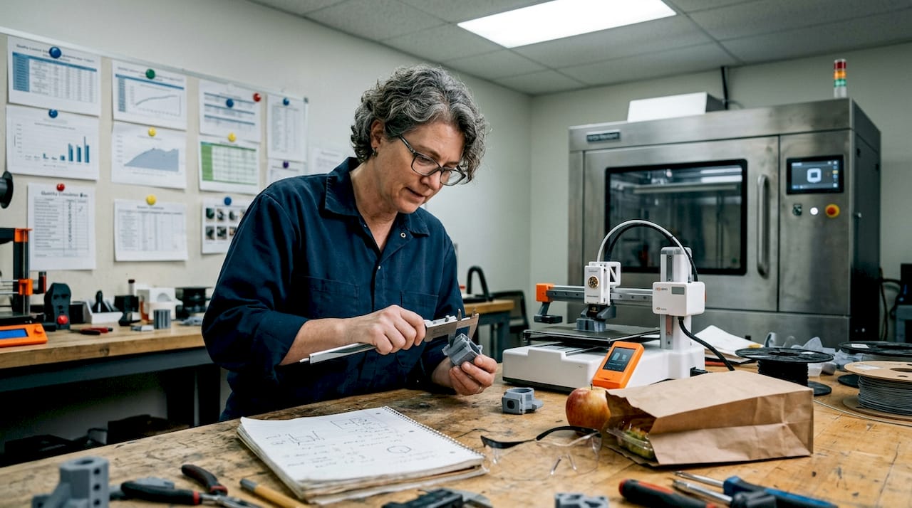
Engineer checking 3D print in cluttered lab workspace

Key 3D Printing Trends Shaping Manufacturing in 2026


TL;DR:

  • The 3D printed nanomaterials market is expected to reach $1.2 billion by 2026, indicating manufacturing is shifting to core strategy.
  • Advanced nanomaterials like graphene and CNTs significantly enhance filament strength, widening application fields in aerospace, automotive, and medical sectors.
  • AI-driven processes improve quality, reduce waste, and democratize additive manufacturing, enabling smarter, more efficient workflows.

The 3D printed nanomaterials market is projected to hit $1.2B in 2026, and that number alone tells you something important: 3D printing is no longer a prototyping curiosity. It is becoming a core manufacturing strategy. For product developers and engineers, the next 12 months will bring real decisions about materials, process economics, AI integration, and supply chain design. Getting these calls right separates teams that ship better products faster from those still debating which printer to buy. This article breaks down the four most consequential trends shaping additive manufacturing in 2026 so you can act on them with clarity.

Table of Contents

Key Takeaways

Point Details
Nanomaterials boost strength Cutting-edge filaments with graphene and CNTs can make 3D-printed parts 50-200% stronger.
Material extrusion leads production FFF/FDM is now the most economical method for large-scale 3D printing, replacing more costly alternatives.
AI powers efficiency AI-driven automation is improving print quality, reducing defects, and making advanced manufacturing more accessible.
ROI shapes equipment choices Firms now choose 3D printing tools based on specific application ROI, not general capabilities.
Hybrid models enhance resilience Combining in-house 3D printing with expert partnerships strengthens supply chains and sustainability.

The rise of advanced materials and nanotechnology

Now that you see the market’s rapid escalation, let’s examine how new materials and nanotechnology are fundamentally changing what’s possible. The short version: filaments are getting dramatically stronger, and the applications that were once limited to metals are opening up to advanced polymers.

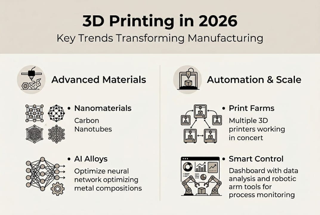
Nanomaterial-infused filaments are boosting tensile strength by 50 to 200%, depending on the base material and the additive used. Graphene and carbon nanotubes (CNTs) are the two most significant contributors here. Graphene adds conductivity and stiffness without adding meaningful weight. CNTs improve impact resistance and thermal stability, which matters enormously in aerospace brackets, automotive housings, and medical device enclosures.

Infographic showing 2026 3D printing trends overview

Beyond filament, artificial intelligence is now being used to design entirely new alloys from scratch. An AI-designed Fe-15Cr steel achieves 1,713 MPa tensile strength with 15.5% elongation, a combination that outperforms many conventionally developed steels. This is not a lab curiosity. It signals that the material design process itself is being automated, compressing the timeline from concept to production-ready specification.

Here is a quick look at how nanomaterial-enhanced filaments compare across key performance categories:

Material type Tensile strength gain Key benefit Primary application
Graphene-infused PLA Up to 50% Conductivity + stiffness Electronics housings
CNT-reinforced nylon Up to 150% Impact resistance Automotive components
Carbon fiber PEEK Up to 200% Thermal stability Aerospace brackets
Nano-silica ABS Up to 80% Surface hardness Medical device casings

The industries moving fastest on this are aerospace, automotive, and medical devices. Each of these sectors demands parts that perform under stress, heat, or sterile conditions. Nanomaterial filaments are starting to meet those bars in ways standard polymers never could.

Key applications driving nanomaterial adoption:

  • Lightweight structural brackets replacing aluminum in aircraft interiors
  • Thermally stable housings for under-hood automotive sensors
  • Biocompatible, high-strength implant guides in surgical planning
  • Electrically conductive enclosures for embedded electronics

Pro Tip: If you are evaluating advanced filaments for a functional part, always request material data sheets with tensile, flexural, and thermal specs. A vendor who cannot provide them is not ready for production-grade work. Our filament 3D printing guide walks through what to look for when selecting materials for real-world applications.

Material extrusion and the economics of 3D printing farms

Material innovations are only as useful as the processes that make them practical. The economics of production are shifting too, especially in extrusion-based 3D printing. Fused filament fabrication (FFF), also called FDM, is gaining serious ground as a production technology, not just a prototyping tool.

Material extrusion is increasingly favored over SLS and MJF for large production farms because the economics simply work better at scale. Lower machine costs, cheaper feedstocks, and easier post-processing make FFF farms a compelling alternative for mid-to-high volume runs of functional parts.

High-filled polymers are a big part of this story. When you load a nylon or PEEK matrix with 30 to 50% carbon fiber or glass fiber, the resulting part can replace die-cast aluminum or zinc in many applications. The weight savings are real, and so is the cost reduction when you factor out tooling.

Here is how FFF stacks up against powder-based processes for production use:

Factor FFF/FDM SLS MJF
Machine cost Low to medium High High
Material cost per kg Low Medium to high Medium to high
Post-processing complexity Low High Medium
Scalability (farm model) Excellent Limited Limited
Part isotropy Moderate High High
Best for Functional parts, tooling Complex geometries High-detail production

Large-format additive manufacturing (LFAM) is also expanding the FFF envelope. Systems that extrude high-filled polymers at scale are now being used for composite tooling, jigs, fixtures, and even mold cores. This is a direct replacement for CNC-machined tooling in some workflows, with lead times measured in hours rather than weeks.

Four reasons manufacturers are building FFF production farms in 2026:

  1. Faster iteration cycles without retooling costs
  2. On-demand production that reduces inventory overhead
  3. Compatibility with advanced composite filaments
  4. Lower operator skill requirements compared to powder-bed systems

If you are still deciding which process fits your production goals, reviewing choosing the right 3D printing method can sharpen that decision. And if you are working at lower volumes, low-volume manufacturing tips covers the practical side of making FFF work efficiently at smaller batch sizes.

AI-driven automation and smarter additive manufacturing

As production scales, ensuring quality and efficiency becomes crucial. Here’s where AI is accelerating change in 3D printing. The technology is moving from a novelty to a genuine process control tool, and the impact is measurable.

Technician monitors AI-driven 3D printing factory

AI optimizes print paths and detects print anomalies, improving reliability across complex geometries and multi-material builds. This matters because traditional quality control in additive manufacturing has always been reactive: you print the part, inspect it, and scrap it if it fails. AI-driven monitoring catches problems mid-print, reducing waste and rework significantly.

Smaller powder particle sizes in powder-bed systems are also enabling smoother surfaces without additional finishing. When combined with AI-optimized scan paths, the result is a part that exits the machine closer to spec. That reduces post-processing time and cost, which is often where additive manufacturing loses its economic advantage.

Where AI is making the biggest difference in AM workflows:

  • Real-time layer inspection using computer vision to flag delamination or warping
  • Generative design tools that propose geometries optimized for both performance and printability
  • Predictive maintenance on print farms to reduce unplanned downtime
  • Automated support structure generation that minimizes material use

Pro Tip: When evaluating a 3D printing partner or in-house system, ask specifically about their quality control process. AI-assisted inspection is becoming a differentiator. If the answer is “we visually inspect after printing,” that is a flag for high-volume or critical-use parts.

“AI is lowering the entry barrier for in-house additive manufacturing,” making it practical for engineering teams without deep AM expertise to run reliable production workflows. (Source)

This democratization effect is significant. Teams that previously needed a dedicated AM specialist to manage process parameters can now rely on software-guided workflows. That does not eliminate the need for expertise, but it does lower the floor for getting started. For engineers exploring how 3D scanning integrates into quality-controlled workflows, achieving high-quality 3D scans covers the metrology side of the equation.

Sustainability, supply chain resilience, and the new AM business model

Digital transformation isn’t just about speed and quality. The business context is evolving as well, introducing new priorities for engineering leaders. Sustainability and supply chain flexibility are now core considerations in how companies structure their additive manufacturing programs.

Supply chain resilience and sustainability are driving adoption of additive manufacturing, with hybrid in-house and expert partnerships becoming the norm. The logic is straightforward: a distributed, on-demand production model is inherently more resilient than a centralized, inventory-heavy one. When a supply disruption hits, teams with AM capability can pivot faster.

“Investments are more cautious, emphasizing utilization and ROI, with a shift toward application-specific machines.” This signals a maturation in how companies approach AM spending.

The sustainability angle is equally real. Additive manufacturing generates significantly less waste than subtractive methods because you are only depositing material where it is needed. Recycled and bio-based filaments are improving in quality, and closed-loop material systems are emerging for powder-bed processes.

What the new AM business model looks like in practice:

  • In-house printers for rapid iteration and low-volume runs
  • Expert service partners for high-complexity or high-volume production
  • Application-specific equipment investments tied to measurable ROI
  • Eco-friendly material sourcing as part of product sustainability commitments

The shift toward application specialization is particularly important. Generalist AM programs that try to do everything with one machine type are losing ground to focused programs that match process to application with precision. If you want to understand how additive manufacturing for sustainability fits into a broader business strategy, that resource covers the foundational business case.

What most forecasts miss about 3D printing’s future

Most 2026 trend coverage focuses on what is new. New materials, new machines, new software. That framing is useful but incomplete, and it can lead engineering teams toward chasing capability rather than building advantage.

The organizations seeing real returns from additive manufacturing are not necessarily the ones with the newest equipment. They are the ones that have invested in specialist knowledge: understanding which material works for which load case, which process minimizes post-processing for their geometry, and which partnership model gives them flexibility without sacrificing quality.

Fast followers who adopt high-profile technologies without that foundational clarity often find themselves with expensive machines running at low utilization. The technology does not create ROI. The application strategy does.

The other thing most forecasts miss is the compounding effect of combining technologies. A team that integrates professional handheld 3D scanning (accuracy to ~0.1 mm) with FFF production and AI-assisted quality control is not just using three tools. They are building a closed-loop manufacturing system that gets smarter over time. That is the real disruptor, not any single technology in isolation.

If you want to see what that looks like in practice, 3D printing on demand is a good starting point for understanding how flexible production models actually function.

Connect with advanced 3D printing solutions

The trends covered in this article are not theoretical. They are shaping real production decisions right now, and the teams that move with clarity will build durable advantages in their markets.

https://cc3dlabs.com

At CC 3D Labs, near Philadelphia, we align directly with where manufacturing is heading in 2026. From advanced filament-based production to professional handheld 3D scanning (accuracy to ~0.1 mm) and CAD support, our 3D printing services are built for engineers who need precision, speed, and reliability. Whether you are developing prototypes to functional parts or scaling a production run, we offer free online estimates, design support, and fast turnaround. Let’s build something that performs.

Frequently asked questions

How are nanomaterials impacting 3D printing in 2026?

Nanomaterials are driving 50 to 200% strength gains in printed parts while expanding viable applications into aerospace, automotive, and medical sectors, backed by a $1.2B market in 2026.

Which 3D printing process is most economical for large-scale production?

FFF/FDM is favored for large-scale production farms in 2026 due to lower machine costs, cheaper materials, and simpler post-processing compared to SLS or MJF.

How is AI shaping additive manufacturing workflows?

AI is automating print path optimization, real-time anomaly detection, and quality control, making advanced AM more accessible to engineering teams without deep process expertise.

What business strategies are successful companies using in 2026’s 3D printing landscape?

Leading companies are investing in application-specific machines with clear ROI targets, combining in-house agility with expert service partnerships and prioritizing sustainable materials and on-demand supply chain models.