
TL;DR:
- D scanning transforms physical legacy parts into detailed digital models for reproduction and inspection. It uses various methods, including structured light, laser, photogrammetry, and CT scanning, depending on the required accuracy and internal complexity. Proper workflow integration and documentation are essential to qualify reproduced parts in regulated industries and maximize the value of scan data.
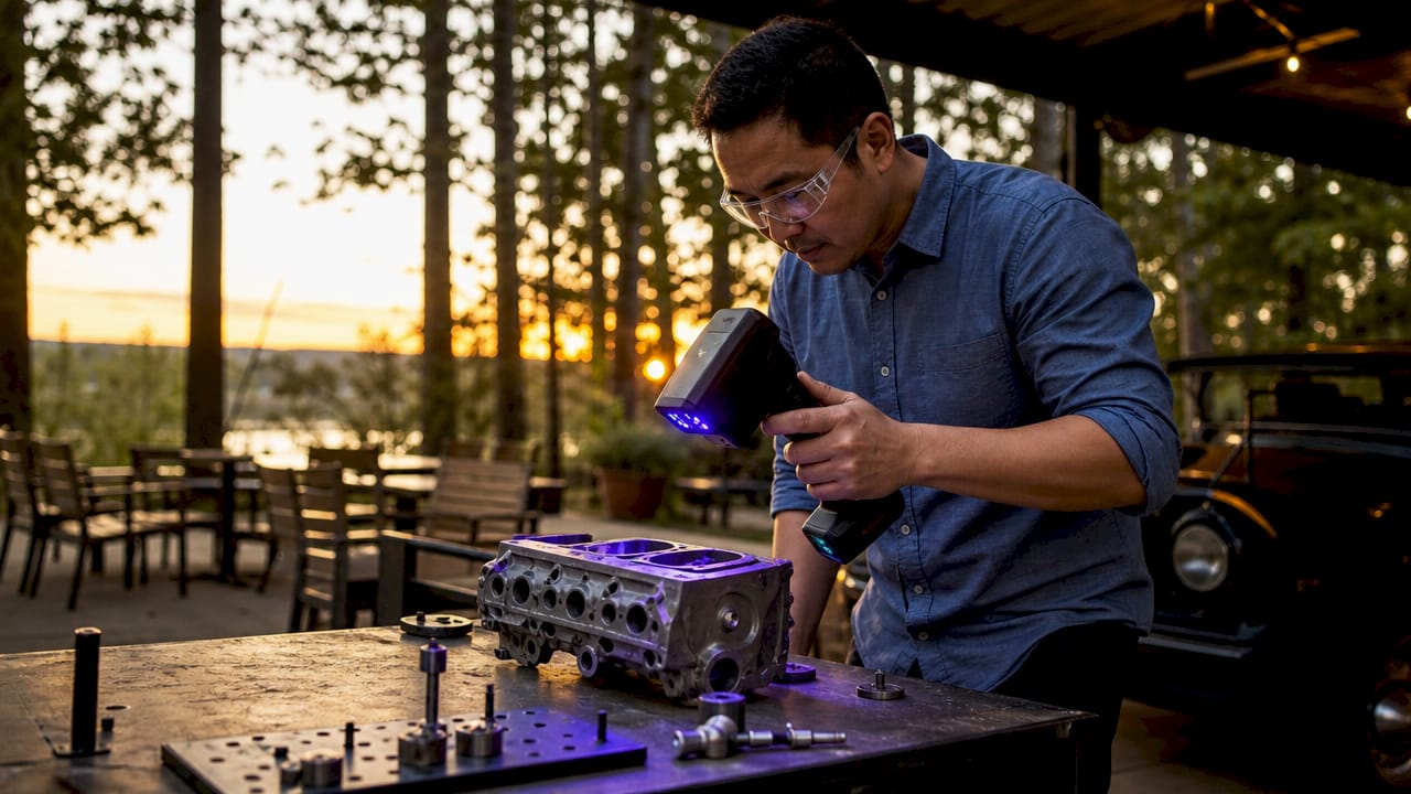
3D scanning is the foundational step in legacy part reproduction, converting physical components into accurate digital models that engineers can inspect, modify, and manufacture from. The process, formally called reverse engineering through digitization, captures geometry down to the micron level. This makes it possible to reproduce parts that have no surviving drawings, no original CAD files, and no active supplier. The role of scanning in legacy part reproduction goes beyond simple copying. It creates a verified digital record that supports future redesign, quality inspection, and regulatory traceability.
What scanning technologies are used in legacy part reproduction?
Four primary technologies drive 3D scanning in reproduction workflows: structured light scanning, laser scanning, photogrammetry, and industrial Computed Tomography (CT) scanning. Each method captures different types of geometry with different levels of accuracy and cost.
Structured light scanners project a grid pattern onto a surface and measure how the pattern deforms. This method captures external geometry with high resolution and works well for machined metal parts, housings, and connectors. Laser scanning uses a similar principle but projects a laser line instead of a grid, making it effective for larger parts and freeform surfaces.
High-resolution photogrammetry offers non-invasive, accurate 3D documentation that preserves surface details with minimal human intervention. It works by processing overlapping photographs through algorithmic pipelines. Photogrammetry is best suited for capturing texture and surface character rather than tight mechanical tolerances.
Industrial CT scanning stands apart from the other three methods. CT scanning generates non-destructive 3D volumetric models that reveal internal features, hidden cavities, and wall thicknesses without disassembling or damaging the original part. This makes CT the only viable option when internal geometry drives the function of the component.
| Technology | Best for | Accuracy | Key limitation |
|---|---|---|---|
| Structured light | External surfaces, small parts | Very high | Limited to line of sight |
| Laser scanning | Large parts, freeform surfaces | High | Surface reflectivity issues |
| Photogrammetry | Texture, surface character | Moderate | Lower dimensional accuracy |
| Industrial CT | Internal features, assemblies | Very high | High cost, slow throughput |
Pro Tip: For parts with both complex external geometry and critical internal channels, combine structured light scanning for the exterior with CT scanning for internal features. This gives you a complete digital model without destroying the original part.
How does scanning integrate into the reverse engineering workflow?
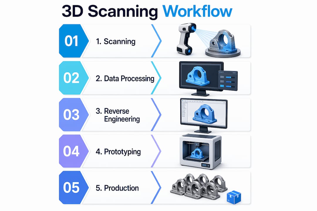
Scanning is one step inside a larger reverse engineering process. Getting that step right requires a structured approach from the moment the physical part arrives.
- Initial assessment. Examine the part for damage, wear, and surface condition. Identify which features are functional and which are cosmetic. This determines which scanning method to use and where to focus resolution.
- Scan execution. Set up the scanner according to part size, material reflectivity, and required accuracy. For shiny metal surfaces, apply a temporary matte spray to reduce noise. Capture multiple passes to cover all angles.
- Data processing. Raw scan data often contains noise and incomplete surfaces. Dedicated software such as Geomagic Design X or Artec Studio processes the point cloud into a clean mesh. Skilled operators are required at this stage. Version control of scan files starts here.
- CAD reconstruction. Convert the mesh into a parametric CAD model using tools like SolidWorks or CATIA. This step requires engineering judgment, not just geometry tracing. The engineer must decide which features are nominal and which reflect wear or damage.
- Validation. Compare the reconstructed CAD model against the original scan data. Deviation maps highlight where the model diverges from the physical part. Acceptable tolerances depend on the application.
Pro Tip: Document engineering intent at every step. Note why a feature was modeled a certain way, especially when the physical part shows wear. That reasoning becomes part of the evidence chain needed for qualification in regulated industries.
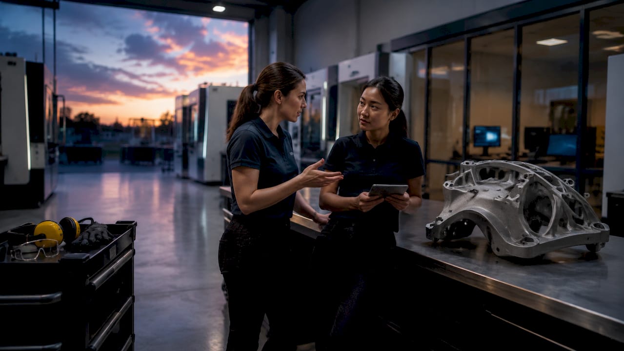
Establishing a traceable qualification workflow that links part assessment, material identification, and scan data version control is the defining challenge in regulated sectors. Aerospace, defense, and medical manufacturers cannot simply reproduce geometry. They must prove the reproduction meets the original performance standard.
What are the benefits and challenges of 3D scanning for legacy parts?
The benefits of part scanning are concrete and measurable. Metrology-grade scanning achieves precision as fine as 10 microns, capturing fine surface details and complex mechanical interfaces that manual measurement cannot reliably document. That level of accuracy eliminates the guesswork that comes with calipers and hand sketches.
Key benefits include:
- Geometry capture without contact. Scanning preserves fragile or worn parts during the documentation process.
- Speed. A structured light scanner can capture a full part surface in minutes. Manual measurement of the same part could take hours.
- Complex feature documentation. Freeform surfaces, compound curves, and organic shapes that are impossible to measure manually are captured completely.
- Digital twin creation. The scan becomes a permanent digital record for future inspection, redesign, or reproduction.
The challenges are equally real. Many reverse engineering projects stall because teams treat the work as a scanning task rather than a full data, compliance, and workflow integration effort. Geometry capture is necessary but not sufficient.
Specific challenges engineers face:
- Data volume. High-resolution scans generate large point cloud files that require significant computing resources and organized storage.
- Engineering intent. A scan captures what the part looks like now, not what it was designed to be. Worn features, corrosion, and deformation all appear in the scan data.
- Material validation. Additive manufacturing material behavior differs from original manufacturing methods. Geometry matching alone does not qualify a reproduced part for service.
- Audit trails. Regulated industries require documented evidence chains linking every decision from scan to final part.
Pro Tip: Build your evidence chain from day one. Log the scan date, operator, equipment calibration record, software version, and every processing decision. Retrofitting this documentation after the fact is expensive and often incomplete.
How do manufacturers apply scanning in practical production workflows?
The practical applications of digitization for legacy parts extend well beyond creating a one-time reproduction. Manufacturers use scan data across multiple production and maintenance scenarios.
High-fidelity scanning combined with additive manufacturing connects classical part geometry with modern digital production methods. A scanned digital twin can feed directly into a 3D printer for rapid prototyping, or into a CNC machining center for subtractive production. The same scan data supports both paths, which reduces lead time when a manufacturer needs to evaluate multiple production options quickly.
You can also use scan-derived digital twins for design accuracy and prototyping improvements. Engineers overlay the scan of a worn part against the original CAD model to measure how the part has changed in service. This data informs redesign decisions and helps predict future failure modes.
| Application | Scanning input | Outcome |
|---|---|---|
| Spare part reproduction | Full surface scan | Replacement part manufactured to original geometry |
| Wear analysis | Scan vs. nominal CAD | Quantified deviation map for maintenance planning |
| Rapid prototyping | Scan to mesh to print | Physical prototype in hours for fit and function testing |
| Aftermarket servicing | Scan of discontinued part | New supplier tooling created without original drawings |
| Quality inspection | Scan of produced part | Automated comparison against design intent |
Aftermarket and legacy vehicle servicing represent one of the highest-value applications. When a manufacturer discontinues a component and the original tooling no longer exists, a high quality 3D scan of a surviving example becomes the only path to reproduction. This is common in aerospace MRO (maintenance, repair, and overhaul), classic vehicle restoration, and industrial equipment servicing.
The production efficiency gains are direct. Eliminating manual measurement and manual redrawing removes two of the most error-prone steps in legacy part reproduction. Scan data feeds manufacturing equipment directly, which reduces the number of iterations needed to achieve a conforming part.
Key Takeaways
Scanning is the critical first step in legacy part reproduction, but traceable workflow integration, material validation, and engineering documentation determine whether a reproduced part qualifies for service.
| Point | Details |
|---|---|
| Scanning precision matters | Metrology-grade scanners capture geometry to 10 microns, far beyond manual measurement capability. |
| Technology selection is part-specific | CT scanning is required for internal features; structured light works best for external surfaces. |
| Workflow integration is non-negotiable | Reverse engineering projects fail when teams treat scanning as the only task rather than one step in a documented process. |
| Material validation is separate from geometry | A geometrically accurate scan does not automatically qualify a reproduced part, especially in regulated industries. |
| Digital twins extend value beyond reproduction | Scan data supports wear analysis, quality inspection, and future redesign, not just one-time part replication. |
Why scanning alone will not save your legacy part program
Most manufacturers I work with come to scanning with the right instinct but the wrong expectation. They assume that once the scan is done, the hard part is over. The opposite is true.
The scan gives you geometry. What it does not give you is engineering intent, material specification, or a qualification record. A worn part scanned at 10 microns of accuracy still gives you a worn part. The engineer has to decide which dimensions represent the design and which represent 40 years of service. That judgment call is not in the scan file.
The manufacturers who succeed with legacy reproduction treat the scan as the beginning of a documented evidence chain, not the end of a measurement task. They track every decision, every software version, and every material substitution. In aerospace and defense, that chain is what gets a part approved. In commercial manufacturing, it is what prevents a costly recall.
The shift I see in 2026 is toward combined workflows where scanning, CAD reconstruction, additive manufacturing, and inspection all share the same data thread. Tools like Authentise and similar manufacturing execution platforms are making this more accessible. But the discipline of documentation still comes from the engineering team, not the software. If you are starting a legacy part program, build the process before you buy the scanner.
— Justin
Cc3dlabs scanning and reproduction services for legacy parts
Cc3dlabs operates a professional 3D scanning lab near Philadelphia that supports manufacturers, engineers, and product developers with metrology-grade scanning and scan-to-CAD processing. The team handles structured light scanning for external geometry and works with clients on full reverse engineering workflows from initial scan through digital twin creation.

For manufacturers who need to move from scan data to physical parts, Cc3dlabs connects scanning directly to 3D printing and production services that support both rapid prototyping and functional part reproduction. Whether you need a single replacement component or a documented reproduction workflow for a regulated application, Cc3dlabs provides the precision and traceability support the job requires. Request a free online estimate to get started.
FAQ
What is the role of scanning in legacy part reproduction?
3D scanning converts a physical legacy part into an accurate digital model that engineers can use to reproduce, inspect, or redesign the component. It is the foundational step in reverse engineering when no original drawings or CAD files exist.
Which scanning method is best for internal part features?
Industrial CT scanning is the correct method for internal features. It generates non-destructive 3D volumetric models of hidden cavities, wall thicknesses, and internal assemblies without altering the original part.
Does scanning alone qualify a part for reproduction in regulated industries?
Scanning alone does not qualify a part. Regulated industries require a traceable qualification workflow that documents part assessment, material identification, scan data version control, and material validation alongside the geometric scan data.
How accurate is metrology-grade 3D scanning?
Metrology-grade 3D scanning achieves precision as fine as 10 microns. That level of accuracy captures fine mechanical interfaces and complex surface details that manual measurement methods cannot reliably document.
What software is used to process raw scan data into CAD models?
Tools like Geomagic Design X and Artec Studio process raw point cloud data into clean meshes. Engineers then use parametric CAD platforms such as SolidWorks or CATIA to reconstruct manufacturable models from the processed scan data.