
TL;DR:
- Print tolerance standards define the acceptable dimensional deviations in 3D printed parts, ensuring proper fit and function. Achieving the correct tolerances depends on machine accuracy, material shrinkage, and thoughtful design to prevent errors and meet industry standards. Validating these tolerances through test prints and systematic measurement is essential for reliable, high-quality production.
Print tolerance standards define the allowable dimensional deviation in a 3D printed part so it fits and functions as designed. Get them wrong, and a press fit becomes a loose rattle or an immovable bond. Get them right, and assemblies snap together on the first try. Explaining print tolerance standards is not just an academic exercise. It is the difference between a prototype that validates your design and one that wastes a full production run. This guide covers fit types, material shrinkage, printer accuracy, and testing methods so you can build parts that meet spec every time.
What are print tolerance standards in 3D printing?
Print tolerance standards specify the maximum and minimum acceptable dimensions for a printed part relative to its nominal design size. The industry term for this concept is “dimensional tolerance,” and it maps directly to the ISO 286 system used in traditional machining. In 3D printing, tolerances are harder to hold because every variable, from filament diameter to bed temperature, shifts the final dimension.
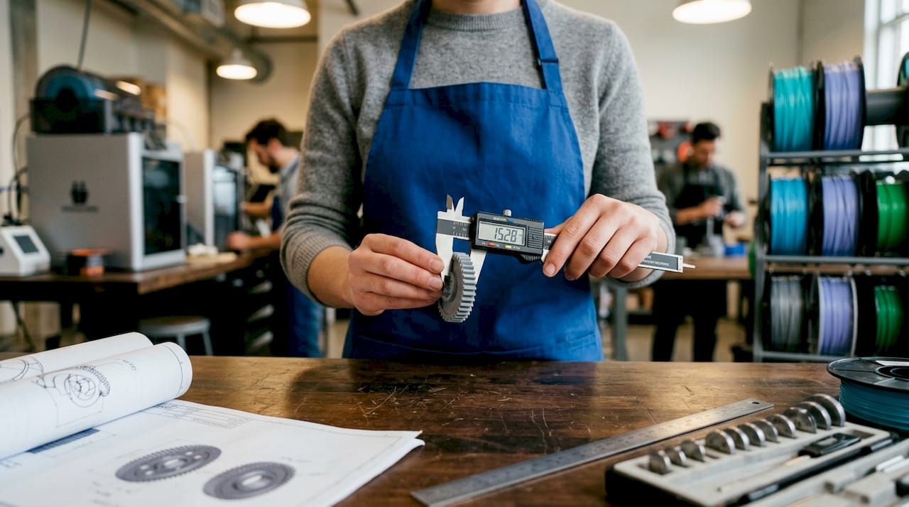
Tolerance depends heavily on use case, fit type, printer model, and material. That means a single tolerance value cannot cover every situation. Engineers must define tolerances per feature, per material, and per machine class.
The practical consequence is significant. A part designed with a 0.2 mm clearance on a budget printer may come out with zero clearance because that machine holds only ±0.3 to ±0.5 mm on a good day. Mid-range machines tighten that to ±0.1–0.3 mm, and precision machines reach ±0.05–0.15 mm. Knowing your machine class before you set tolerances in CAD is the first rule of print quality standards.
What are the typical tolerance values for different fit types?
Fit type determines how much clearance or interference you build into mating parts. The three categories engineers use most are press fit, sliding fit, and loose fit.
| Fit type | Clearance or interference | Typical use |
|---|---|---|
| Press fit | -0.1 to -0.2 mm interference | Permanent joints, bearing seats |
| Sliding fit | 0.2–0.4 mm clearance | Drawers, rails, moving assemblies |
| Loose fit | 0.5–1.0 mm clearance | Pins, alignment pegs, quick-swap parts |
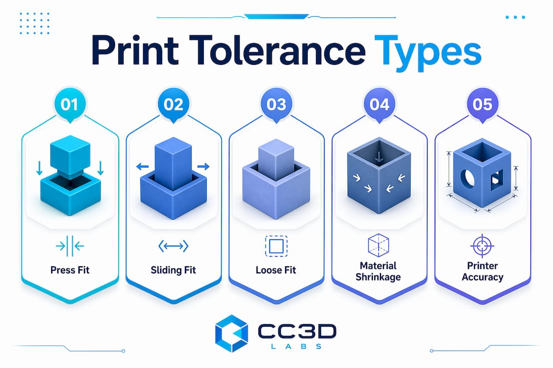
Industry standards recommend 0.1 mm clearance for tight connectors, 0.2–0.4 mm for sliding parts, and 0.5–1.0 mm for loose pins. These values assume a mid-range printer and PLA or PETG. Material choice shifts the numbers considerably.
Press fit interference also varies by material. PLA requires -0.15 to -0.25 mm, PETG needs -0.20 to -0.30 mm, Nylon runs -0.30 to -0.40 mm, and TPU demands -0.40 to -0.60 mm because of its flexibility. A Nylon press fit designed with PLA values will pull apart under load. Always match interference values to the material you are actually printing.
Clearance for peg and hole features ranges from 0.2 mm per side for alignment to 0.4 mm or more for free movement. These are per-side values, so a 10 mm pin in a 10.4 mm hole has 0.2 mm clearance on each side. That distinction trips up many designers who apply total gap instead of per-side gap.
Pro Tip: Build a small test coupon with three or four fit types at different clearances before committing to a full print run. Ten minutes of test printing saves hours of rework.
How do material properties and shrinkage influence 3D print tolerances?
Shrinkage is the single most underestimated variable in understanding print tolerances. Every thermoplastic contracts as it cools, and that contraction pulls dimensions below the nominal CAD value.
The shrinkage rates by material are:
- PLA: 0.3–0.5% shrinkage. Pre-scale models by 100.3–100.5% to compensate.
- ABS and ASA: 0.8–1.2% shrinkage. These materials also warp without an enclosed chamber, which adds unpredictable dimensional error beyond simple scaling.
- Nylon: 1.0–2.5% shrinkage. Pre-scaling by 100.5–102.5% is required, and even then, ambient humidity affects the final dimension because Nylon absorbs moisture.
- TPU: Low shrinkage but high elasticity means interference values must account for the material springing back after assembly.
- PETG: Moderate shrinkage, typically 0.4–0.6%, with better layer adhesion than PLA and less warping than ABS.
Pre-scaling compensates for uniform shrinkage, but shrinkage is rarely uniform. Tall parts shrink more in Z than in X or Y. Wide flat parts warp at the edges. The practical fix is to print a calibration cube, measure all three axes with calipers, and apply axis-specific scale factors in your slicer. A single global scale factor is a starting point, not a solution. Designers working with advanced filament materials should treat shrinkage compensation as a per-material, per-geometry workflow step rather than a one-time setting.
What printer and design factors affect adherence to print tolerance standards?
Printer accuracy sets the ceiling for what tolerances you can hold. Design choices determine whether you reach that ceiling or fall short of it.
Four factors control most of the dimensional error in filament-based printing:
-
Calibration state. An uncalibrated extruder over-extrudes, which thickens walls and closes clearances. E-steps, flow rate, and linear advance settings all affect final dimensions. Recalibrate after every nozzle change or filament switch.
-
Print orientation. Features printed in the XY plane hold tighter tolerances than features built up in Z. Layer lines in Z create stair-stepping on curved surfaces, which adds effective dimensional error. Orient critical mating surfaces to lie in the XY plane whenever possible.
-
Elephant foot effect. The first layer spreads under nozzle pressure and bed adhesion, adding 0.2–0.5 mm to bottom dimensions. That extra material ruins press fits and prevents flat mating surfaces from seating correctly. Chamfering the base by 0.5 mm offsets this effect without requiring slicer compensation.
-
Horizontal holes. Horizontal holes print undersized because filament sags across the unsupported span. Adding 0.2 mm to the hole diameter in CAD, or reorienting the part so the hole axis is vertical, corrects this consistently.
Pro Tip: Add a 0.5 mm chamfer to every base edge as a default in your CAD template. Experienced designers pre-chamfer bases to offset first-layer over-extrusion before the problem ever reaches the printer.
Design strategy matters as much as printer settings. Avoid sharp internal corners on mating features because filament rounds them, reducing effective clearance. Use drafting standards in 3D modeling to add draft angles on vertical walls, which improves dimensional consistency across the full height of a part. Split long mating surfaces into shorter segments to reduce the cumulative effect of warping on fit.
How can manufacturers and engineers test and validate print tolerance compliance?
Testing is the only way to confirm that your tolerance strategy works on a specific printer with a specific material. Assumptions based on spec sheets fail in practice because real-world conditions always differ from controlled lab conditions.
A systematic validation workflow includes these steps:
-
Print a tolerance cube. A 20 mm cube with labeled walls is the baseline. Measure all six faces with digital calipers. Any deviation from 20.00 mm tells you your scale factor and flow rate need adjustment before you print functional parts.
-
Use a pin and slot test model. Print a series of pins and matching slots with clearances ranging from 0.1 mm to 0.5 mm in 0.1 mm steps. The smallest clearance that allows free movement is your sliding fit baseline for that printer and material combination.
-
Apply go/no-go gauges. For production runs, go/no-go gauges are faster than calipers. A go gauge must pass through the feature; a no-go gauge must not. This binary check catches out-of-tolerance parts in seconds without requiring measurement skill.
-
Document results per material and printer. Calibration test prints with dimensional checks identify necessary tolerance adjustments for a given printer and material. Keep a log. When you switch filament brands or update firmware, rerun the test suite and compare against your baseline.
-
Iterate in CAD, not in post-processing. Sanding and drilling to fix tolerance errors is a one-off fix that does not scale. Adjust the CAD model, reprint, and retest. Three iterations typically converge on a working tolerance for a new material and printer combination.
For engineers managing part validation in 3D printing, this workflow should be formalized as a standard operating procedure before any part moves from prototype to batch production.
Key takeaways
Print tolerance standards require matching fit type, material shrinkage, and printer accuracy before a single layer is deposited, because correcting dimensional errors after printing costs more than designing them out.
| Point | Details |
|---|---|
| Fit type sets the baseline | Press fits need -0.1 to -0.2 mm interference; sliding fits need 0.2–0.4 mm clearance. |
| Material shrinkage shifts dimensions | PLA shrinks 0.3–0.5%; Nylon shrinks up to 2.5% and requires axis-specific scale compensation. |
| Printer class limits achievable tolerance | Budget machines hold ±0.3–0.5 mm; precision machines reach ±0.05–0.15 mm. |
| Design choices prevent common errors | Chamfer bases by 0.5 mm and add 0.2 mm to horizontal hole diameters to offset known print artifacts. |
| Test before committing to production | Pin and slot test prints plus go/no-go gauges validate tolerances faster than caliper-only inspection. |
Why I think most engineers underestimate tolerance testing
Most engineers I work with treat tolerance as a CAD problem. They set a clearance value, send the file, and expect the printer to deliver. The printer does not care about your CAD intent. It responds to calibration state, ambient temperature, filament moisture, and a dozen other variables that shift from one print session to the next.
The engineers who consistently hit tight tolerances share one habit: they test systematically and document everything. They know their printer’s actual accuracy range, not the spec sheet range. They know how their preferred Nylon brand behaves after sitting in a humid shop overnight versus a dry box. That knowledge comes only from running test prints and keeping records.
The other thing I have seen change outcomes is designer-engineer collaboration at the tolerance-setting stage, not after the first failed prototype. When the person who understands the assembly function talks to the person who understands the printer before the CAD is finalized, the first print usually fits. When those conversations happen after a failed batch, you are paying twice.
Emerging technologies like in-process dimensional monitoring and closed-loop slicer feedback are starting to reduce the gap between intended and actual dimensions. But in 2026, systematic testing and documentation remain the most reliable path to reliable 3D prototyping that holds tolerance across a full production run.
— Justin
Cc3dlabs precision printing for functional parts
Cc3dlabs operates near Philadelphia and specializes in filament-based 3D printing for functional prototypes, production parts, and batch orders where dimensional accuracy is not optional.

Every order at Cc3dlabs starts with a review of fit requirements, material selection, and tolerance targets before a file goes to the printer. The team supports press fits, sliding assemblies, and loose-fit components across PLA, PETG, Nylon, TPU, and specialty filaments. For engineers who need parts that meet spec on the first run, Cc3dlabs offers professional 3D printing services with design support, free online estimates, and local pickup or shipping. If your current workflow is producing out-of-tolerance parts, the right starting point is a conversation about material, machine, and fit requirements.
FAQ
What is a standard tolerance for 3D printed parts?
Standard tolerances range from ±0.3–0.5 mm on budget printers to ±0.05–0.15 mm on precision machines. The right value depends on fit type, material, and the specific printer being used.
How much clearance should I add for a sliding fit?
A sliding fit requires 0.2–0.4 mm of clearance between mating surfaces. Start at 0.3 mm for a mid-range printer with PLA or PETG, then adjust based on test print results.
Why do my 3D printed holes come out too small?
Horizontal holes print undersized because filament sags across the unsupported span during printing. Add 0.2 mm to the hole diameter in CAD or reorient the part so the hole axis is vertical.
How do I compensate for material shrinkage in 3D printing?
Pre-scale your model by the inverse of the shrinkage rate. PLA needs 100.3–100.5% scaling; Nylon may need up to 102.5%. Measure a calibration cube after printing and apply axis-specific corrections for best results.
What is the fastest way to validate print tolerances?
Print a pin and slot test model with clearances from 0.1 mm to 0.5 mm in 0.1 mm steps. The smallest clearance that allows free movement is your working sliding fit tolerance for that printer and material.