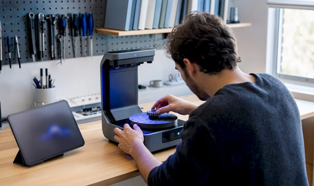
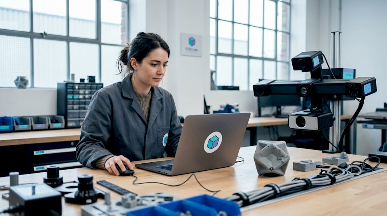
Technician scanning small mechanical part

Types of Objects Suitable for 3D Scanning: 2026 Guide


TL;DR:

  • Object size, surface texture, and material compatibility determine the suitable 3D scanning technology for each project. Small objects benefit from high-resolution structured light or laser scanners, while large structures often require photogrammetry or LiDAR methods. Proper surface preparation and understanding of material properties are essential to achieve accurate, clean digital captures suited to the object’s intended use.

Types of objects suitable for 3D scanning are defined by three core factors: size, surface texture, and material compatibility with the chosen scanning technology. Whether you are a product developer reverse engineering a mechanical part, an artist digitizing a sculpture, or a manufacturer capturing a prototype for quality control, the object itself determines which scanner you need and how you prepare for the job. Methods like photogrammetry, structured light scanning, and laser scanning each perform differently depending on what sits in front of them. Getting that match right from the start eliminates rework and produces cleaner data.

1. Types of objects suitable for 3D scanning: small and medium items

Small and medium objects represent the most common category scanned for prototyping, dental applications, and jewelry design. Items like rings, crowns, miniature figurines, and small mechanical components all fall here. Resolution matters more than raw accuracy at this scale. A scanner that captures 0.01mm surface detail will reveal geometry that a general-purpose device misses entirely.

Surface preparation is the deciding factor for scan quality on small objects. Metallic jewelry and polished prototypes reflect light back at the scanner, creating noise and holes in the mesh. Applying a thin layer of AESUB Blue vanishing spray allows structured light scanners to capture high-detail geometry without permanently altering the object. The spray evaporates on its own within hours, leaving no residue.

  • Jewelry and rings: Require blue structured light or laser scanning due to metallic reflectivity
  • Dental models: Demand sub-0.05mm accuracy; turntable setups with automated rotation are standard
  • Small prototypes and mechanical parts: Benefit from handheld or desktop structured light scanners
  • Figurines and collectibles: Photogrammetry works well when surface texture is matte and detailed

Pro Tip: Automated turntables improve consistency for small objects by minimizing stitching gaps and delivering uniform angular coverage. For dental models and jewelry, this repeatability is not optional. It is the difference between a usable scan and a session you repeat three times.

2. Large and architectural objects: challenges and approaches
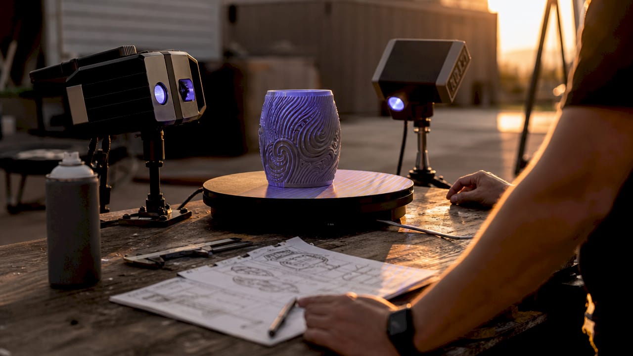
Close-up of turntable scanning setup for small object

Large objects like buildings, vehicles, aircraft fuselages, and industrial equipment present a different set of constraints. You cannot place a building on a turntable. The scanner must come to the object, and the data volume grows exponentially with scale. Photogrammetry scales effectively with camera placement, making it the dominant method for structures where sub-millimeter precision is not the primary goal.

When precision does matter at large scale, pulse-based and phase shift technologies take over. Long-range 3D scanners using these technologies are specifically engineered for buildings, military vehicles, and industrial equipment. Phase shift scanners offer faster data acquisition at medium range, while pulse-based systems reach farther with slightly lower point density.

Object type Recommended technology Key consideration
Buildings and facades Photogrammetry or LiDAR Environmental lighting control
Vehicles and aircraft Phase shift or handheld laser Access to undercarriage and interior
Industrial equipment Pulse-based long-range scanner Scale and occlusion management
Large sculptures Photogrammetry Texture richness aids reconstruction

Environmental control is the hidden challenge at large scale. Wind, changing sunlight, and vibration all degrade scan quality. Scheduling outdoor scans during overcast conditions reduces harsh shadows that distort mesh reconstruction. For interior architectural scans, turning off fluorescent lighting and using the scanner’s own projected pattern eliminates competing light sources.

3. Surface materials and textures: how composition affects scan quality

Surface material is the single most disruptive variable in 3D scanning. Reflective, transparent, and very dark surfaces all defeat standard scanning methods in different ways. A chrome-plated part scatters structured light unpredictably. A glass bottle transmits the scanner’s projected pattern rather than reflecting it. A matte black rubber gasket absorbs light and returns almost no signal.

Blue laser technology is the preferred solution for dark or reflective metal surfaces, while infrared technology is favored for scanning human subjects due to comfort and reduced light sensitivity. This distinction matters practically. Scanning a polished stainless steel bracket requires a different scanner than scanning a foam prototype or a human face.

  • Reflective metals: Use blue laser scanning or apply AESUB vanishing spray before structured light capture
  • Transparent objects: Apply matte spray or painter’s tape to create a scannable surface layer
  • Dark rubber or foam: Blue laser or high-sensitivity structured light; increase exposure settings
  • Matte plastics and ceramics: Compatible with nearly all scanning methods; photogrammetry works well

Matte sprays and painter’s tape are standard workarounds for glossy or transparent surfaces. Painter’s tape applied to a glass object creates a textured, opaque surface the scanner can read. The tape is removed after scanning, and the geometry underneath is reconstructed from the captured shell. It is a low-cost fix that saves hours of post-processing.

Pro Tip: Before committing to a full scan session on a difficult material, test on a proxy object with similar surface properties. A chrome-plated test piece from a hardware store costs almost nothing and tells you exactly how your scanner responds before you risk a client’s irreplaceable part.

4. Functional and artistic applications: objects scanned for prototyping and design

The intended end-use of a scan determines how much accuracy and detail you actually need. A museum-grade archival scan of a Roman coin requires maximum fidelity and color accuracy. A game-ready asset of the same coin needs optimized topology and a fraction of the polygon count. Different applications require varying accuracy levels, from high-poly archival masters to low-poly performance-optimized models.

Here is how object types map to their primary scanning applications:

  1. Mechanical parts for reverse engineering: Require dimensional accuracy within 0.02mm or better; structured light or industrial laser scanning is standard
  2. Product prototypes: Scanned to verify geometry against CAD files; design accuracy is the primary metric
  3. Sculptures and fine art: Photogrammetry captures color and texture simultaneously; hybrid workflows add structured light for precise geometry
  4. Cultural artifacts and museum pieces: Hybrid workflows combining photogrammetry for texture and structured light for geometry produce archival-grade digital twins
  5. Human subjects for medical or fashion use: Infrared structured light scanning; fast capture minimizes subject movement artifacts
  6. Architectural elements for renovation: Photogrammetry or LiDAR; outputs feed directly into BIM software like Autodesk Revit

The connection between end-use and scan specification is direct. Scanning a prototype for a manufacturing quality check demands tighter tolerances than scanning the same part for a marketing render. Defining the output requirement before you scan prevents over-engineering the capture process and saves time in post-processing.

5. Comparing scanning methods by object type and material

Choosing the right scanning method is not about buying the most expensive hardware. Analyzing object size, surface qualities, and intended use before attempting a scan reduces rework and produces better outcomes. The table below maps the four primary technologies to their strongest use cases.

Scanning method Best object types Strengths Limitations
Photogrammetry Large textured objects, sculptures, buildings Low cost, scalable, captures color Struggles with featureless or shiny surfaces
Structured light Small to medium parts, dental, jewelry High resolution, fast capture Limited range; sensitive to ambient light
Laser scanning Reflective metals, industrial parts Works on dark and shiny surfaces Higher cost; slower than structured light
LiDAR Buildings, outdoor environments, vehicles Long range, fast point cloud Lower resolution for fine surface detail

Photogrammetry excels on large textured objects while structured light and laser scanning outperform it on smaller metallic and reflective surfaces. This is not a hierarchy. It is a tool-to-task match. A $500 photogrammetry setup with a DSLR and Meshroom software can outperform a $10,000 structured light scanner when the object is a textured stone wall. The reverse is equally true for a polished aluminum housing.

Handheld scanners offer flexibility for irregular shapes, while turntable scanners provide repeatability and speed for small, manageable objects. For professionals running high-volume scanning workflows, the turntable approach reduces per-scan time significantly and standardizes output quality across batches.

Key takeaways

Matching object size, surface material, and intended use to the correct scanning technology is the single most important decision in any 3D scanning project.

Point Details
Size determines scanner type Small objects need high-resolution desktop or turntable setups; large objects require photogrammetry or long-range LiDAR.
Surface material drives technology choice Reflective and transparent surfaces require blue laser scanning or surface preparation with matte spray before capture.
End-use defines required accuracy Archival and reverse engineering scans demand tight tolerances; artistic or game-ready assets prioritize optimized geometry.
Preparation prevents rework Testing on proxy objects and controlling lighting conditions before the final scan eliminates the most common failure points.
Hybrid workflows solve complex objects Combining photogrammetry for texture with structured light for geometry captures both color and precision in one pipeline.

What I have learned from scanning hundreds of objects

The most expensive mistake I see professionals make is selecting a scanner based on brand reputation rather than object characteristics. A high-end structured light scanner is the wrong tool for a textured sandstone facade, no matter how good the spec sheet looks. The object tells you what it needs. Your job is to listen.

Surface preparation is where most scans are won or lost before the scanner even turns on. I have watched teams spend hours in post-processing trying to fill holes that a two-minute matte spray application would have prevented entirely. The 3D scanning checklist approach, where you assess material, size, and lighting before touching the hardware, consistently produces cleaner first-pass data than any amount of software correction afterward.

The other insight that took me time to internalize: photogrammetry is not a budget compromise. For large, richly textured objects, it is genuinely the best tool available. A controlled photogrammetry session with a calibrated camera and diffuse lighting will outperform a rushed laser scan on a building facade every time. The misconception that quality scans require expensive hardware persists because people conflate cost with capability. They are not the same thing.

— Justin

Bring your objects to life with Cc3dlabs

Whether you are scanning a precision mechanical part, a one-of-a-kind sculpture, or a batch of product prototypes, the quality of your scan determines everything that follows.

https://cc3dlabs.com

Cc3dlabs offers high-accuracy 3D scanning services near Philadelphia, covering a full range of object types from small jewelry and dental models to large industrial components. The team handles surface preparation, technology selection, and post-processing so your data arrives clean and ready for CAD modeling, printing, or archival. If you are ready to move from physical object to precise digital model, Cc3dlabs provides the expertise and equipment to do it right the first time. Explore the full range of printing and scanning services or request a free estimate directly on the site.

FAQ

What objects are hardest to 3D scan?

Transparent, highly reflective, and very dark objects are the most difficult to scan accurately. Surface preparation with matte spray or painter’s tape resolves most of these issues before scanning begins.

Can photogrammetry scan small objects like jewelry?

Photogrammetry can capture small objects, but structured light or blue laser scanning delivers significantly higher resolution for items like jewelry and dental models where fine surface detail is critical.

What is the best scanning method for mechanical parts?

Structured light or industrial laser scanning is standard for mechanical parts requiring dimensional accuracy within 0.02mm or better. The choice between the two depends on whether the surface is matte or reflective.

Do I need expensive equipment to get quality 3D scans?

Not always. Photogrammetry with a calibrated camera and controlled lighting produces high-quality scans of large, textured objects at a fraction of the cost of dedicated hardware. For small or reflective objects, specialized scanners are necessary.

How does object size affect which scanner I should use?

Small objects require high-resolution desktop or turntable scanners. Large objects like buildings and vehicles are best captured with photogrammetry, LiDAR, or long-range laser systems that scale with the object’s dimensions.
Engineer reviewing 3D scan data in office

Why 3D Scan Data Integrity Is Crucial for Manufacturing


TL;DR:

  • High-resolution scans alone do not guarantee usable data, as accuracy, repeatability, and traceability are essential for reliable 3D imaging. Environmental conditions, operator technique, calibration, and software processing all threaten data integrity, which must be systematically protected through calibration, controlled environments, and documented workflows. Ensuring data integrity accelerates manufacturing, reduces errors, and improves project outcomes by providing dependable, traceable scan results.

High-resolution scans look impressive, but resolution alone does not determine whether your data is usable. Understanding why 3D scan data integrity is crucial separates professionals who consistently hit tolerances from those who keep chasing errors back to the source. Data integrity covers accuracy, repeatability, traceability, and processing quality. Miss any one of those, and even a visually detailed point cloud can collapse your prototyping workflow before a single part is printed or machined. This article explains what integrity actually means in a scanning context, what threatens it, and how to protect it at every stage of your workflow.

Table of Contents

Key Takeaways

Point Details
Resolution does not equal accuracy A high-resolution scan can still contain dimensional errors that ruin a prototype or manufactured part.
Integrity is a system-level property Hardware, software, operator technique, and environment must all work together to produce trustworthy data.
Calibration is non-negotiable Regular, traceable calibration prevents measurement drift and keeps scan data defensible for manufacturing acceptance.
Environment and operator matter as much as hardware Temperature gradients, vibration, and poor scanning technique introduce errors that even premium scanners cannot correct.
Reliable data accelerates the entire workflow Confident scan data reduces rework, speeds up iteration, and lowers the cost of production errors.

Why 3D scan data integrity is crucial: the core concepts

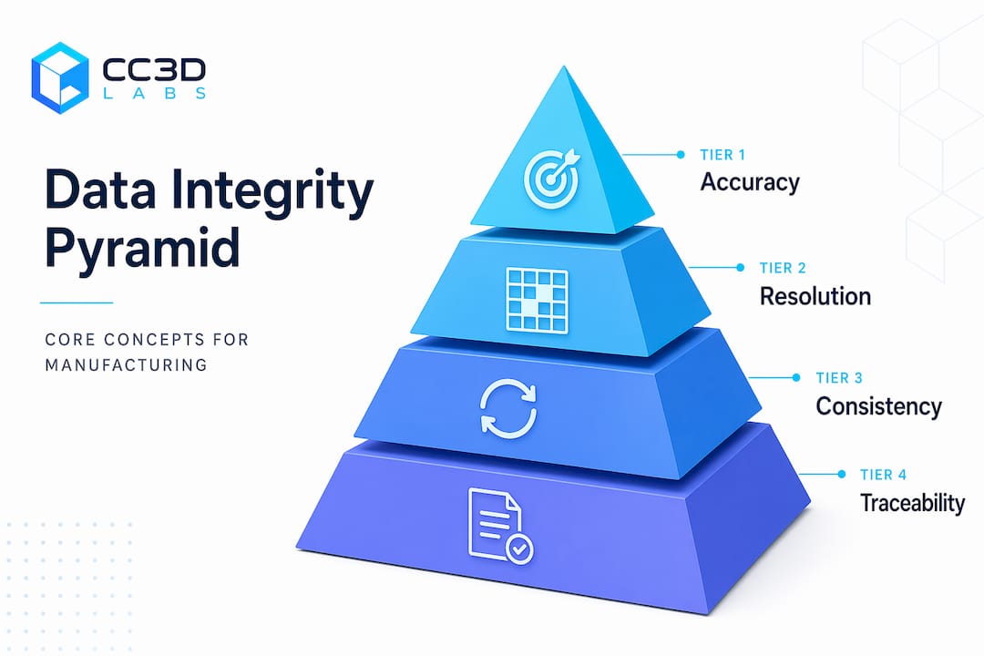
Before you can protect data integrity, you need a precise definition of what it includes. Four concepts form the foundation: accuracy, resolution, consistency, and traceability. Most professionals use the first two interchangeably, and that habit costs time and money.

Accuracy vs. resolution

Resolution and accuracy serve fundamentally different functions. Resolution describes how much surface detail the scanner captures. Accuracy describes how close those captured dimensions are to the physical truth of the object. A scanner can produce a beautifully detailed mesh at 0.05 mm point spacing that still carries a 0.3 mm dimensional error. In a product development workflow, the detail impresses stakeholders during review. The dimensional error shows up as a misfit during assembly.

High resolution also carries a practical cost. Excessive point density inflates file size, bogs down mesh repair, and slows every downstream process from CAD alignment to slicing. Matching resolution to intended use is not a compromise. It is the correct engineering decision.

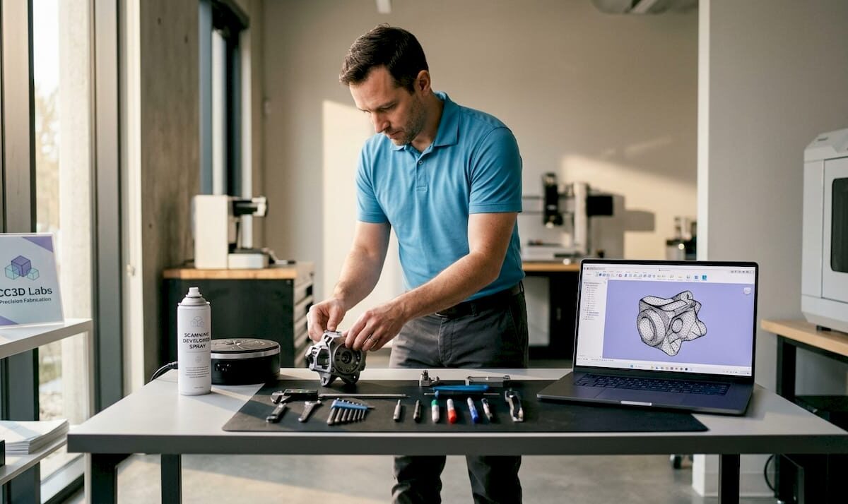
Technician repairing scan mesh at lab bench

Consistency and traceability

Infographic pyramid showing scan data integrity concepts

Reliable scan data depends on repeatability, not just one good result. If scanning the same part twice under identical conditions produces meaningfully different outputs, nothing in your workflow is defensible. Consistency lets you trust comparisons, revisions, and inspection sign-offs.

Traceability ties your scan results to a verifiable standard. Calibrated reference artifacts, documented scan settings, and formal quality reports are what transform a point cloud from a visual deliverable into a manufacturing document. Consider the difference between a scan submitted to a contract manufacturer alongside a formal quality report that documents control points, outlier handling, and calibration history versus one submitted without any of that context. The first one gets approved. The second one gets questions.

  • Accuracy: Dimensional closeness to the physical object, measured against traceable standards
  • Resolution: Point density and surface detail, which should be matched to the specific use case
  • Consistency: Repeatability across sessions, operators, and equipment states
  • Traceability: Documentation linking scan results to calibrated standards and documented procedures

Together, these four elements define what strong 3D scanning data reliability actually looks like in practice.

Common threats to scan data integrity

Understanding the risks is not about pessimism. It is about knowing exactly where to focus your attention. Data integrity in 3D scanning is an emergent property, meaning it arises from multiple interacting layers rather than from any single component. When vulnerabilities in those layers align, even a capable scanner produces flawed data. This is the Swiss-cheese model applied to metrology workflows.

Here are the most common sources of failure, ranked by how often they are overlooked:

  1. Environmental conditions. Temperature, lighting, and vibration are the most underestimated threats to scan accuracy. Thermal expansion in a part being scanned in a warm production floor can shift dimensions measurably between the start and end of a single scan session. Air temperature gradients create measurement drift that no post-processing step can fully undo.

  2. Operator technique. The scanning path, standoff distance, overlap between passes, and handling of reflective or dark surfaces all introduce variability. Two operators scanning the same part with the same scanner can produce outputs that differ by more than the printed tolerance on the drawing.

  3. Hardware calibration drift. Sensors drift. Mechanical components develop play. A scanner that produced accurate results six months ago may no longer meet its stated specifications if calibration has not been maintained. This is particularly dangerous because the data often looks normal while carrying hidden dimensional errors.

  4. Software processing errors. Registration algorithms, mesh smoothing filters, and hole-filling routines all make decisions that affect dimensional truth. Default settings are not optimized for every geometry or material. Blindly applying them without understanding the tradeoffs is a common source of data degradation.

  5. Multiple interacting failures. The Swiss-cheese model predicts that single layers of defense rarely fail catastrophically on their own. An error in any one area is manageable. When poor environmental control, a drift-affected sensor, and aggressive mesh smoothing align in the same workflow, the result is data that looks clean but fails downstream.

Pro Tip: Before a major scan session, run a reference artifact through your full workflow, from capture to processed mesh. If the output falls outside your expected tolerance range, stop and find the cause before scanning the actual part.

Best practices to protect and maintain data quality

Knowing the threats is useful. Having a system to counter them is what actually protects your data. Reliability is a system-level outcome driven by calibration, environment, operator discipline, and software controls working together. No single action is enough on its own.

Calibration and traceable standards

Calibrate your scanner on a scheduled basis using certified reference artifacts. Document every calibration event with date, environmental conditions, and results. This documentation is what makes your data defensible for manufacturing acceptance in contract environments.

Modern high-accuracy scanners in 2026 can achieve volumetric accuracy of 0.03 mm + 0.05 mm per meter using multi-line laser modes, but that performance is only realized when calibration is current and conditions are controlled.

Hardware selection and environment control

Factor What to prioritize What to avoid
Scanner grade Metrology or industrial grade with stable housing Consumer devices for tight-tolerance work
Connectivity Onboard processing with dual Wi-Fi to prevent data loss Wireless setups that stream raw packets without error correction
Environment Temperature-controlled, vibration-dampened, diffuse lighting Bright window light, HVAC drafts, concrete floors near heavy machinery
Surface prep Matte reference spray or targets for reflective/dark surfaces Relying on raw surface appearance without preparation

Software and post-processing controls

Do not treat post-processing as cleanup. Every filter and alignment decision is a data modification. Use the minimum smoothing necessary for your application. Document the processing settings applied to each dataset. For high-quality manufacturing scans, the goal is mesh fidelity to the physical object, not visual appeal.

Pro Tip: Save both the raw point cloud and the processed mesh as separate files. If an alignment or filtering decision turns out to be wrong during CAD review, you can reprocess from raw data without rescanning the part.

  • Align scans using physical reference targets, not just software-generated feature matching
  • Run mesh quality checks before exporting, including hole counts, intersecting faces, and non-manifold edges
  • Match your export format and polygon count to what the downstream tool actually needs

The business impact of accurate scan data

The significance of 3D data integrity becomes clearest when you trace it directly to project outcomes. Reliable scan data reduces costly downstream failures and builds confidence in every decision that follows the scan. That effect compounds quickly in iterative product development.

Consider a typical reverse engineering project. A product team scans an existing component to create a replacement part. If the scan carries a 0.2 mm accuracy error and the designer does not detect it, the CAD model inherits that error. The prototype is printed or machined to that incorrect model. The fit test fails. The team scans again, remodels, reprints. Each cycle costs time and materials. The root cause was never the printing or machining. It was the scan data.

The importance of 3D scan accuracy is equally clear in inspection workflows. When scan data is traceable and consistent, it serves as a legal and contractual record of part geometry at a specific point in time. That record supports quality sign-offs, warranty claims, and deviation approvals with documented evidence rather than verbal assurance.

  • Accurate scan data cuts the number of prototype iterations by giving designers a reliable baseline to work from
  • Clean, well-structured mesh files reduce prep time in CAD and slicing software, directly lowering labor costs per part
  • Traceability documentation supports ISO and AS9100 quality requirements, which matter in aerospace, medical, and automotive supply chains
  • Consistent data across scan sessions makes it possible to detect genuine part wear or tooling drift, rather than noise from scan variability

For teams doing rapid prototyping, the benefits of accurate 3D scans are not abstract. They show up in the number of design cycles completed per week, the scrap rate on first-article inspection, and the speed of design sign-off. Those are the metrics that determine project profitability.

My take on where most teams go wrong

I have reviewed a lot of 3D scanning workflows over the years, and the pattern that frustrates me most is not carelessness. It is misplaced focus. Teams spend considerable money on a premium scanner and then operate it in conditions that undermine every advantage the hardware offers. The scanner becomes a status symbol rather than a calibrated instrument.

The misconception I run into most often is that a higher price tag or a more impressive spec sheet guarantees better data. It does not. A well-operated mid-range scanner in a controlled environment with a disciplined operator consistently outperforms a high-accuracy instrument scanned on a vibrating factory floor by someone who has not been trained on the specific geometry they are capturing.

What I have learned from working through enough failed prototypes is that workflow discipline matters more than any single tool upgrade. Calibration schedules, environmental logs, processing documentation, and reference artifacts are unglamorous. They do not appear in marketing materials. But they are the actual mechanism by which good data gets produced reliably, not occasionally.

My honest recommendation is to build your scanning protocol before you buy your next scanner. Understand exactly what the workflow demands in terms of accuracy, consistency, and traceability. Then select hardware that fits that protocol. The teams that do this consistently produce better outcomes than teams chasing the highest-spec device without a system around it.

— Justin

Get reliable scan data with Cc3dlabs

If this article has clarified what 3D scan data integrity actually requires, the logical next step is working with a team that applies these principles on every project. Cc3dlabs provides professional handheld 3D scanning (accuracy to ~0.1 mm) services from our facility near Philadelphia, and data quality is built into the workflow, not treated as an afterthought. Every scan includes calibration verification, documented processing steps, and output quality checks designed to support prototyping and manufacturing use.

https://cc3dlabs.com

Whether you are reverse engineering an existing component, inspecting a manufactured part, or generating scan data for a new prototype, our 3D scanning and prototyping guide walks you through how we approach accuracy and reliability at each stage. For hands-on preparation before your next scan session, the scanning accuracy checklist covers the specific steps that prevent the most common sources of data degradation. When you are ready to move from scanning to production, our full printing and prototyping services handle everything from single prototypes to batch production runs with the same commitment to dimensional accuracy.

FAQ

What does 3D scan data integrity actually mean?

Data integrity in 3D scanning means the captured data accurately and consistently represents the physical object with traceable, documented quality. It covers accuracy, repeatability, and the controls used during capture and processing.

How is accuracy different from resolution in 3D scanning?

Accuracy measures dimensional closeness to the real object, while resolution measures how much surface detail is captured. A high-resolution scan can still contain significant accuracy errors that cause problems in manufacturing.

What are the biggest threats to scan data quality?

Environmental factors like temperature and vibration, calibration drift, operator technique, and uncritical post-processing are the most common causes of data degradation, and they interact to compound errors.

How do I know if my scan data is good enough for manufacturing?

Run the processed mesh through a dimensional comparison against a calibrated reference artifact, check mesh quality metrics including non-manifold edges and holes, and document the calibration state of your scanner at the time of capture.

Why does 3D scanning data reliability matter for prototyping?

Unreliable scan data propagates errors into every downstream step, from CAD modeling to print or machining. Catching and correcting those errors at the source saves multiple prototype cycles and the costs that come with them.

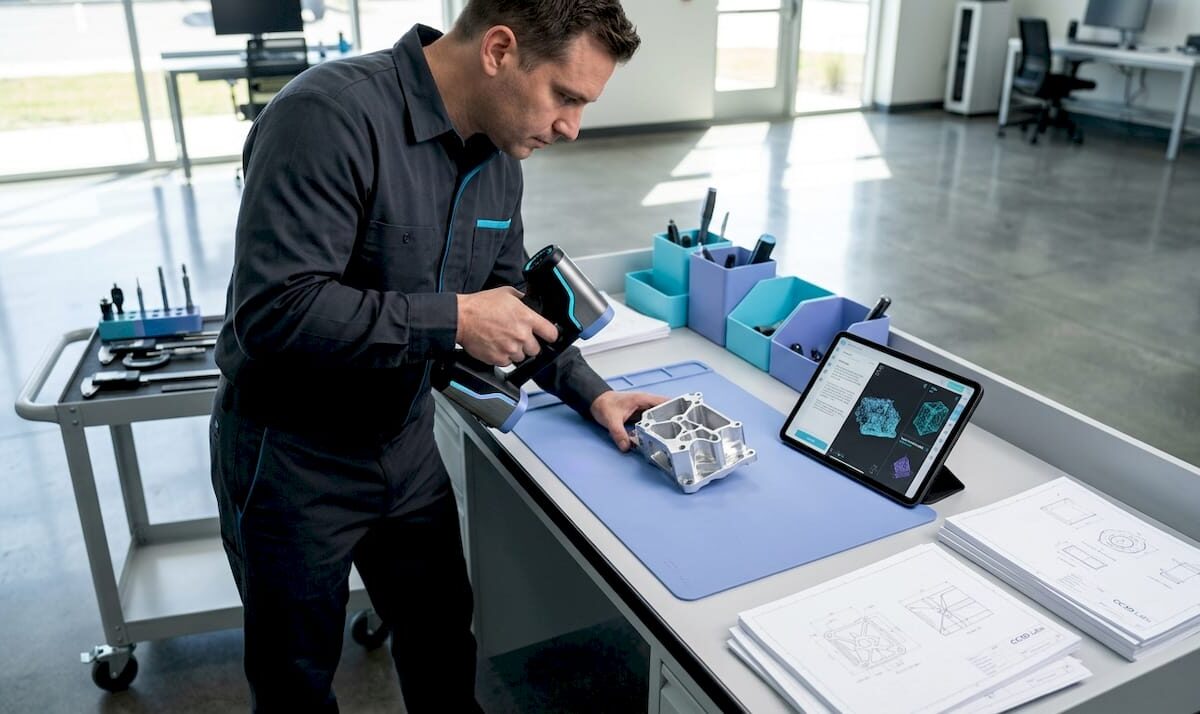
Technician preparing object for 3D scanning in workspace

How to Optimize 3D Scan Accuracy for Better Results


TL;DR:

  • Achieving precise and consistent 3D scan data requires thorough object preparation, appropriate scanner selection, and deliberate environmental control. Techniques like multi-angle scanning, slow overlapping passes, and real-time coverage checks significantly improve accuracy. Post-processing, including careful alignment, noise removal, and validation against references, is essential for producing reliable models.

Getting consistent, precise data from a 3D scanner is harder than the product demos make it look. Whether you’re capturing a machined part for reverse engineering, scanning an organic form for product development, or working up a prototype at home, knowing how to optimize 3D scan accuracy separates usable data from a frustrating rebuild. Incomplete geometry, surface noise, and misaligned point clouds are not hardware problems — they’re technique problems. This guide covers every phase from object prep through post-processing so you can get it right the first time.

Table of Contents

Key Takeaways

Point Details
Prepare surfaces before scanning Apply matte spray to reflective or dark objects to significantly improve point cloud quality.
Multi-angle scanning closes data gaps Scanning horizontally and vertically captures crevices and undercuts a single pass will miss.
Slow, overlapping movement is non-negotiable Erratic scanner movement causes tracking loss and leaves data holes that are hard to repair later.
Post-processing must be methodical Align, then clean noise, then fill holes in that order to avoid compounding errors in your mesh.
Verify accuracy against a reference Compare your scan output against physical measurements or a CAD model before committing to production.

How to optimize 3D scan accuracy before you start

Most accuracy problems are baked in before the scanner ever powers on. Preparation is where you make or break the final result, and it deserves more attention than most guides give it.

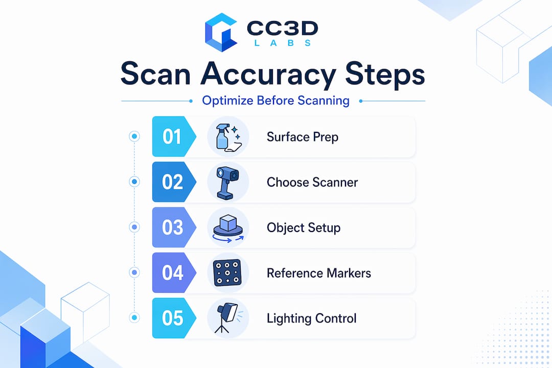
Surface treatment comes first. Objects with reflective, transparent, or very dark surfaces frequently require matte spray to improve scan fidelity. Structured light and photogrammetry-based scanners rely on reading surface texture and light patterns. A polished aluminum bracket or a black rubber gasket gives the sensor almost nothing to work with, producing sparse, noisy point clouds. A quick coat of removable scanning spray gives those surfaces the diffuse reflectivity they need.

Match your scanner to the object. A long-range LiDAR unit designed for architectural capture will not resolve the fine features of a 30mm mechanical component. Conversely, a close-range structured light scanner with a small field of view will lose tracking on a large enclosure. Before you scan, confirm your scanner’s rated accuracy, resolution, and working distance are appropriate for the object’s size and the level of detail you need to capture.

Infographic showing five steps to optimize 3D scan accuracy

Control your environment deliberately. Harsh shadows and direct sunlight cause errors and reduce model fidelity in ways that post-processing cannot fully recover. Set up in a space with soft, diffuse lighting. Overcast daylight works well outdoors. Indoors, use diffused studio lights or even translucent panels over standard fixtures. Avoid scanning near windows with strong directional sun.

Here’s a pre-scan checklist worth running through every time:

  • Clean the object of dust, grease, and fingerprints
  • Apply scanning spray to reflective, transparent, or very dark areas
  • Stabilize the object on a turntable or non-slip mat so it cannot shift mid-scan
  • Confirm ambient lighting is soft and consistent from all angles
  • Check that the scanner is fully warmed up and recently calibrated

Pro Tip: Place your object on a lazy Susan turntable with reference markers printed on the mat underneath. The scanner tracks the markers while you rotate the object, giving you automatic alignment across passes without any repositioning guesswork.

Step-by-step scanning techniques for better precision

With prep complete, what you do during the scan determines how much cleanup you create for yourself afterward. These techniques directly support improving 3D scanning precision.

  1. Move slowly and use overlapping passes. Slow, steady movement with overlapping passes prevents tracking loss and gaps in data. A general rule: each new pass should share at least 30% overlap with the previous one. Think of it like mowing a lawn rather than driving across a field.

  2. Alternate between horizontal and vertical scanner orientations. Rotating the scanner vertically reveals hidden crevices and undercuts that horizontal scanning misses entirely. This is one of the most underused techniques for capturing complex objects. Run a full horizontal pass, then tilt the scanner 90 degrees and make a dedicated vertical pass over any concave areas, threads, or slots.

  3. Apply markers to challenging or symmetrical surfaces. Markers improve scan stability and reduce tracking loss for objects with uniform color, repetitive geometry, or large featureless flat sections. Stick retro-reflective targets in irregular patterns across the object’s surface. The scanner uses these as fixed reference points when natural texture is insufficient.

  4. Adjust exposure and resolution settings for each object. A shiny metallic surface needs lower exposure than a matte plastic part to avoid overblown returns. Reduce resolution slightly on large, simple forms to keep file sizes manageable. Max out resolution only when fine surface detail genuinely matters for your downstream workflow.

  5. Scan from multiple orientations to ensure full coverage. Combining scans from different positions produces more complete coverage of hard-to-reach areas. For most freeform objects, plan for at least three to five distinct scan positions: top, front, back, and both sides at minimum.

  6. Monitor tracking feedback in real time. Most scanning software shows a live tracking indicator. If it starts to drop, stop and back up slightly rather than pushing forward. Recovering lost tracking mid-scan is almost always cleaner than trying to repair the resulting gap in post.

Pro Tip: For symmetrical objects like cylindrical parts or spherical housings, break the symmetry artificially by taping a small piece of masking tape in an irregular position. This gives the scanner a unique reference point to track across the full rotation.

Post-processing best practices for accurate models

Raw scan data is never the finished product. The post-processing phase is where you turn a rough point cloud into a dimensionally accurate mesh, and how you approach it matters as much as the scan itself.

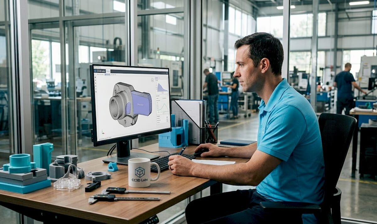
Engineer post-processing 3D scan model on computer

Align before you clean. When working with multiple scan passes, register and align all scans first before touching noise removal or mesh operations. Trying to merge passes after you’ve already modified one of them creates mismatches that can be nearly impossible to reconcile.

Post-processing steps like noise removal, mesh alignment, and hole filling are critical to preserving model accuracy. The order matters:

  • Alignment and registration. Use your software’s global registration function after doing a rough initial alignment. Software with advanced point cloud registration can significantly improve results, particularly when scans have limited overlap. Displacement-corrected geometric consistency algorithms are now making their way into commercial tools and dramatically improve reliability in low-overlap conditions.
  • Noise and outlier removal. Use statistical outlier filters with conservative settings. Aggressive noise removal destroys fine surface detail. Run the filter once at low strength, then visually inspect before applying again.
  • Hole filling and mesh repair. Fill small holes automatically, but handle large holes manually. Automated tools will often interpolate surface curvature incorrectly across wide gaps, creating geometry that was never actually scanned.
  • Export format selection. Export in formats appropriate to your workflow. OBJ and STL are standard for 3D printing and CAD import. PLY retains color and per-point metadata if you need it for inspection or archival. STEP or IGES are better for direct CAD environments when your software supports scan-to-CAD conversion.

Pro Tip: Before you export, run a quick visual inspection by cross-sectioning the mesh in your software. Slicing through the model at several planes reveals internal voids, duplicate geometry, and inverted normals that won’t be obvious from the outside.

Common mistakes that compromise scan accuracy

Even experienced operators repeat these errors. Knowing what to watch for saves you a full rescan.

  1. Ignoring environmental factors. Environmental vibrations, temperature swings, or air movement degrade scan quality by introducing noise and tracking errors. A large HVAC unit cycling on and off near your scan table is enough to introduce measurable error over a long scan session. Scan in a stable, quiet environment whenever precision is critical.

  2. Scanning too fast. Speed feels productive but erratic or rapid movements cause incomplete or misaligned scan passes. The scanner needs time to process and register each frame. Double the time you think you need for any object with complex geometry.

  3. Skipping regular calibration. Skipping calibration leads to inaccurate dimensions and misaligned scans, especially in engineering applications where tolerances are tight. Calibrate at the start of each session, after transport, and any time the scanner has been exposed to significant temperature change.

  4. Not checking coverage in real time. On-site quality checks during scanning reduce rework and improve model completeness. Discovering a missing area when you’re back at your desk means setting up the whole scan again. Spend 30 seconds reviewing coverage before you move the object.

“The single most expensive mistake in 3D scanning is assuming you got it. Verify before you move anything.” This is worth repeating every time you scan a critical part.

Verification methods that confirm scan accuracy

Producing a mesh is not the same as producing an accurate mesh. These techniques help you know which one you have.

Verification method What it checks When to use it
Physical measurement comparison Key dimensions against calipers or CMM data Before any manufacturing commitment
CAD overlay deviation map Color-coded deviation between scan and CAD Reverse engineering and inspection workflows
Point cloud overlap analysis Percentage of coverage and alignment error After merging multiple scan passes
Reference target residuals Error values from marker-based alignment Whenever markers are used during scanning

For high-stakes applications, compare your scan against a physical measurement reference at multiple checkpoints, not just the overall bounding dimensions. A scan can look dimensionally correct at the extremes while carrying localized errors in complex features. CAD overlay tools in software like Geomagic or Polyworks generate heat maps that visualize exactly where deviation is occurring and by how much.

Advanced algorithms like displacement-corrected geometric consistency significantly improve point cloud registration accuracy, particularly in low-overlap conditions. If your scanning software has registration quality scoring, pay attention to it. A high alignment error at the merge stage means your final model carries that error everywhere downstream.

Pro Tip: Scan a known reference object, such as a calibrated sphere or gauge block, at the start of each session. Measure it in software and compare to its certified dimensions. This gives you a real-world accuracy baseline for that specific scan session, not just the manufacturer’s spec sheet.

My honest take on mastering 3D scan accuracy

In my experience, the biggest gap between mediocre scans and exceptional ones is not hardware. I’ve watched engineers with top-tier scanners produce unusable data because they were in a hurry, and I’ve seen hobbyists with mid-range units capture engineering-grade geometry because they were patient and methodical.

Real-time verification changed how I work. I used to finish a full scan session and find missing coverage back at the workstation. Now I treat verification as part of the scanning workflow, not a step after it. That single habit cut my rescan rate dramatically.

The other thing I’ve learned: multi-angle scanning is not optional on anything with undercuts, threads, or deep pockets. A single-pass horizontal scan of a threaded housing looks complete until you try to use the mesh and realize all the thread geometry is missing. Adding a dedicated vertical pass takes five extra minutes and saves an hour of repair work.

The myth I push back on hardest is that a better scanner solves accuracy problems. It doesn’t. Technique, environment, and patience solve accuracy problems. The scanner is just the measurement tool. How you use it determines everything.

Get professional-grade 3D scanning and printing with Cc3dlabs

https://cc3dlabs.com

If you’re working on a project where accuracy genuinely matters, whether it’s a functional prototype, a reverse-engineered component, or a production part series, the DIY path has real limits. Cc3dlabs offers professional handheld 3D scanning (accuracy to ~0.1 mm) services alongside full-cycle 3D printing for engineers and product developers who need results they can trust. The team near Philadelphia handles everything from scan capture through final print, so your data quality is validated at every step. You can also explore the scanning accuracy checklist on the site to cross-reference your current workflow against professional standards. Get a free estimate online or reach out directly if you have a complex part that’s been giving you trouble.

FAQ

What causes poor accuracy in 3D scans?

Poor accuracy most often comes from environmental issues, surface conditions, and scanning technique rather than hardware. Reflective surfaces, harsh lighting, rapid scanner movement, and skipped calibration are the leading causes.

How many scan passes do I need for a complete model?

Most objects require at least three to five distinct scan orientations to achieve full coverage. Complex parts with undercuts, crevices, or internal features need more, and a dedicated vertical-orientation pass is often required.

Do I need scanning spray for every object?

Not every object needs it, but any surface that is highly reflective, transparent, or very dark should be treated. These surface types cause sparse or noisy point clouds that are difficult to repair in post-processing.

How often should I calibrate my 3D scanner?

Calibrate at the start of every scan session, after transporting the scanner, and after any significant temperature change. Skipping calibration introduces dimensional drift that accumulates across a session.

What file format should I export for engineering use?

OBJ and STL work well for most 3D printing applications. For CAD integration and inspection workflows, STEP or IGES formats preserve geometric data more reliably when your software supports scan-to-CAD conversion.

Technician calibrating 3D scanner in workshop

Archival 3D Scanning Guide for Product Development Precision


TL;DR:

  • Most engineers mistakenly assume that any 3D scan qualifies as archival, which can jeopardize long-term reuse. Achieving true archival 3D scanning requires detailed measurement records preserved in durable, open formats, alongside comprehensive documentation and calibration data. Proper workflow planning, including defining coordinate systems, controlling scan conditions, and maintaining metadata, is essential to ensure digital assets remain useful for decades.

Most engineers assume that any 3D scan is an archival scan. That assumption quietly kills product development programs. True archival 3D scanning means capturing high-fidelity 3D measurements of a physical object and preserving the resulting datasets, including raw scan data, derived models, and metadata, in durable, long-term formats designed for reuse years or even decades later. For product developers and manufacturers, that distinction is not academic. It determines whether your digital record can actually drive a reprint, a tolerance audit, or a design iteration in five years without starting from scratch.

Table of Contents

Key Takeaways

Point Details
Engineered for reuse Archival 3D scanning creates precise digital records that enable reliable prototyping and manufacturing, even decades later.
Workflow and validation matter Careful planning, calibration, and documentation make the difference between true archival utility and data loss.
No single file standard Long-term success relies on preserving both raw and interoperable files, plus metadata about methods and conditions.
Quality depends on application Material, surface, and intended use all impact how you capture and accept 3D scan data for the archive.

Archival 3D scanning: Definition and core concepts

With a shared understanding of why preservation matters, let’s clarify exactly what archival 3D scanning entails and why it differs from what most people picture.

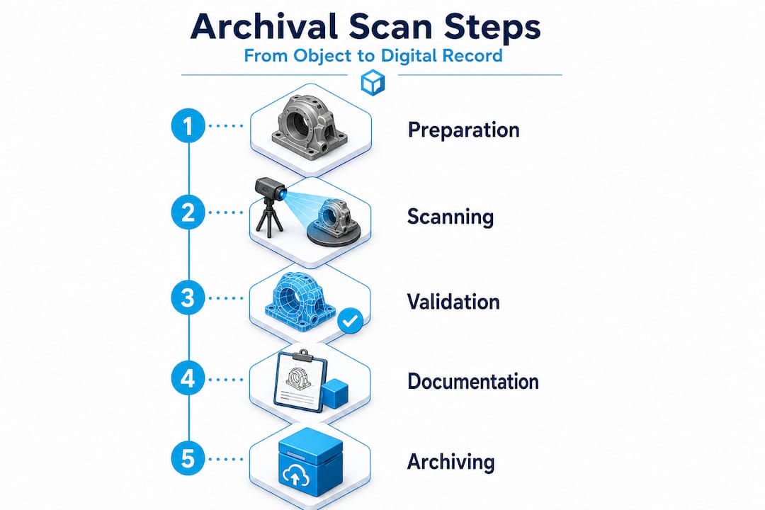
An archival 3D scan is not simply a mesh you can rotate on screen. It is a structured measurement record built to survive software migrations, personnel changes, and years of engineering reuse. That distinction separates it from the ad-hoc scans common in hobbyist workflows or single-use inspection tasks, where the goal is a quick visualization, not long-term data fidelity.

Vertical infographic showing archival 3D scan steps

Professional practice treats scans as measurement records that feed controlled workflows, including control networks, traceable deliverables, and field records, not just visualization models. This is precisely the standard that product engineers need to adopt.

The core concepts behind archival scanning include:

  • High-resolution capture: Point cloud density sufficient to resolve the finest functional features on your part
  • Traceable coordinate systems: Every dataset is registered to a defined spatial reference, so geometry is reproducible
  • Calibration documentation: The scanner’s measurement uncertainty is recorded, not assumed
  • Metadata preservation: Capture date, operator, equipment, ambient conditions, and processing parameters accompany every dataset
  • Controlled deliverable formats: Both raw scan files and processed derivatives are retained separately

“Archival quality is not a feature of the scanner. It is a property of the workflow, the documentation, and the intent behind the capture.”

Understanding design accuracy and prototyping requirements from the start lets your team define what “archival” actually means for your specific use case, whether that is heritage documentation, reverse engineering, or first-article inspection.

Critical workflow elements for archival 3D scanning

Understanding the goals of archival scanning, we next examine what it takes, in practice, for a scan to achieve those standards.

Engineer reviewing 3D scan accuracy checklist

The most common failure mode in archival scanning programs is treating the scan session itself as the entire workflow. In reality, the scan session is just the first step. What transforms raw point cloud data into a true archival resource is the controlled measurement package that surrounds it.

Your scanning checklist for accuracy should address five non-negotiable workflow elements:

  1. Coordinate system definition: Establish a fixed reference frame before scanning begins. Use physical control targets, monuments, or reference artifacts that can be reproduced in future sessions. Without a defined coordinate system, your scan is a floating geometry with no spatial anchor.
  2. Registration and control strategy: Document how individual scan positions were merged. Record the targets used, the registration algorithm, and the resulting residual errors. This documentation allows future engineers to verify alignment or re-register datasets from scratch if needed.
  3. Calibration and uncertainty documentation: Every scanner has a stated accuracy specification, but real-world accuracy depends on surface properties, distance, angle of incidence, and environmental conditions. Record the calibration certificate, the pre-capture validation routine, and any uncertainty estimates specific to the captured object.
  4. Raw file preservation: Never discard the original point cloud or structured scan data. Raw files are the ground truth. Processed meshes and derivative CAD models are interpretations. If your processing software introduces artifacts, the raw data is your only path to recovery.
  5. Metadata and provenance records: Log everything that a future engineer would need to understand the capture: scanner model, firmware version, resolution settings, ambient temperature, lighting conditions, and the name of the person who performed the scan.

Pro Tip: Create a standardized scan log template and require it to be completed before any scan session is closed out. Treat it like a lab notebook entry. Future engineers will thank you, and so will your quality management system.

The table below summarizes the key deliverables in a properly structured archival measurement package:

Deliverable Format Purpose
Raw point cloud Proprietary + open (e.g., .e57, .las) Ground truth reference
Registered scan assembly Project file + exported .e57 Reproducible spatial reference
Processed mesh .obj, .stl, or .ply Engineering and manufacturing use
Calibration record PDF or structured document Uncertainty traceability
Coordinate system definition Report or README file Spatial context for future users
Metadata log Structured text or database entry Provenance and repeatability

Following documentation strategies for workflows used in other precision industries reveals a pattern: the teams that document obsessively are the teams that can reproduce results years later without heroic reverse engineering efforts.

A high quality scan process also accounts for fixture design, lighting control, and surface preparation before the scanner is ever switched on. These upstream decisions directly determine whether your archived data is usable or merely stored.

For teams that want to access professional-grade equipment and validated workflows without building an in-house lab, partnering with a dedicated 3D scanning lab dramatically reduces the risk of workflow gaps.

Quality control: Materials, surfaces, and scan acceptance

With the core workflow defined, the next challenge lies in managing variable scan quality and ensuring reliable results across different object types.

Here is a fact that surprises many engineers early in their archival scanning programs: the scanner model matters far less than the strategy around it. Surface characteristics and acquisition conditions fundamentally change what is achievable in terms of accuracy, completeness, and dimensional fidelity. As a result, archival success depends on capture strategy, validation, and fit-for-purpose uncertainty, not only the scanner model.

The materials and surfaces that cause the most trouble in engineering environments include:

  • Highly polished or mirror-finish metals: Structured light and laser scanners struggle with specular reflections, producing noise or gaps in the point cloud
  • Transparent or translucent materials: Glass, clear polycarbonate, and acrylic are nearly invisible to most scanning technologies without surface treatment
  • Carbon fiber and dark matte composites: High light absorption causes inconsistent returns and reduced point density
  • Small radii and sharp internal corners: Occlusion and beam divergence limit coverage in tight geometries
  • Large flat surfaces: Can look easy but are prone to alignment drift during stitching if control targets are insufficient
Surface type Common challenge Recommended strategy
Polished metal Specular reflection, point cloud noise Apply matte scanning spray or use photogrammetry targets
Transparent plastic Scanner cannot detect surface Apply temporary matte coating, remove after scanning
Dark composite Low return signal, incomplete coverage Increase scan exposure or apply reference dots
Complex internal geometry Occlusion, coverage gaps Multi-angle capture with validated coverage maps
Large flat panels Alignment drift during stitching Dense target field with certified reference distances

Pro Tip: Define your acceptance criteria before you scan, not after. Set minimum point density thresholds, maximum allowable deviation from reference measurements, and coverage completeness requirements for each part type. This prevents the common situation where a scan session is declared “done” based on visual inspection of the mesh rather than verified measurement performance.

“A scan that looks complete on screen and a scan that is dimensionally complete are not the same thing. Only your acceptance criteria tell the difference.”

Achieving scan quality on engineering parts with challenging surfaces often requires a combination of technologies, structured light for geometry, photogrammetry for reference targets, and contact measurement for ground-truth validation on critical features. No single method covers every scenario, and the importance of 3D prototyping quality becomes apparent the moment a downstream manufacturing process depends on a scan that was never properly validated.

Archival file formats and long-term data preservation

Reliable scanning and quality control are just the start. To realize the enduring value of your scans, you must think strategically about file formats and data management.

One of the most common misconceptions is that choosing the right file format is a single decision made at the end of a scan session. In reality, format strategy needs to be baked into your workflow from day one.

Archival 3D preservation practices commonly emphasize retaining original, raw scan data and using open or interoperable formats for long-term access, while acknowledging there is no single universally agreed archival file format. That means your format strategy must be deliberately constructed rather than defaulted into.

Best practices for long-term data preservation include:

  • Retain raw master files: Keep the original capture files in the scanner’s native format alongside exported open formats. Native formats contain the most complete data, while open formats ensure future accessibility.
  • Use a dual-track approach: Maintain one copy in the most complete format available (often proprietary) and a second copy in a widely readable open format such as .e57 for point clouds or .obj and .ply for meshes.
  • Store metadata separately and explicitly: Do not rely on metadata embedded in the file header alone. Write a separate README or structured document that captures every piece of provenance information.
  • Version your derivative models: When you process a raw scan into a mesh or CAD model, keep a record of what processing steps were applied and what software version was used.
  • Plan for format migration: No format is permanent. Schedule periodic reviews of your archive to assess whether stored formats remain accessible with current software, and migrate to updated formats before the old ones become unreadable.
Format Type Strengths Limitations
.e57 Point cloud (open) Widely supported, stores metadata No mesh representation
.las / .laz Point cloud (open) Common in survey workflows Limited metadata fields
.ply Mesh (open) Stores color and normals Less common in CAD workflows
.obj Mesh (open) Universal readability No intrinsic coordinate metadata
.stl Mesh (open) Universal for manufacturing No color, limited precision
Native formats (.zprj, .fls, etc.) Proprietary Maximum data fidelity Software-dependent, risk of obsolescence

Understanding the full landscape of top CAD file formats helps teams make informed decisions about which derivatives to produce and which formats will survive software upgrades over a ten-year horizon.

The uncomfortable truth: Why archival 3D scanning rarely succeeds without planning

Armed with best practices, let’s take a candid look at the rarely discussed pitfalls and what separates archival success from irretrievable data loss.

Most archival 3D scanning programs fail quietly. They do not fail dramatically with error messages or system crashes. They fail years later when an engineer opens a scan archive and finds that the metadata is missing, the coordinate system was never documented, the software that created the native files is no longer available, and the raw data was overwritten to save storage space. At that point, the “archive” is just a collection of orphaned meshes.

The root cause is almost always the same: teams treated archival scanning as a data collection task rather than an engineering discipline. Scanning is the physical act. Archival scanning is the system of decisions, documentation, and maintenance that makes those scans permanently useful.

Because there is no single universal archival 3D file format, engineers need to implement a dual track strategy, retaining raw and master files alongside interoperable derivatives, and preserving metadata and provenance so future teams can reconstruct the intended geometry and processing parameters without guesswork.

The mindset shift required here is significant. Stop thinking of your scan archive as a file folder and start thinking of it as a controlled measurement library. Every entry in that library should be retrievable, understandable, and reproducible by someone who was not in the room when the scan was captured.

What we have seen consistently at CC 3D Labs is that teams who invest in upfront planning, defining their acceptance criteria, establishing their coordinate systems, and committing to their dual-track format strategy before the first scan session, build archives that actually get used. Teams that treat these steps as optional administrative overhead end up rebuilding scans from scratch at exactly the wrong moment, typically when a key product is facing a design change or a regulatory audit.

A commitment to innovation in product development means treating your digital records with the same rigor you apply to your physical parts. Your scan archive is a manufacturing asset. Protect it accordingly.

Next steps: Partnering for archival 3D scanning and prototyping success

For product developers who are ready to move from theory to practice, the fastest path to a functional archival scanning program is partnering with a lab that already understands the nuances of measurement-grade capture and long-term data management.

https://cc3dlabs.com

CC 3D Labs provides professional handheld 3D scanning services (accuracy to ~0.1 mm) near Philadelphia, serving product developers and engineering teams who need scans that are genuinely fit for manufacturing, not just for viewing. Our workflows address coordinate system setup, calibration documentation, multi-format deliverables, and provenance records as standard practice, not add-ons. Whether you are reverse engineering a legacy component, creating a first-article inspection baseline, or building a long-term digital archive for a product line, we can structure a scanning program that meets your specific engineering requirements. Explore our scanning for accuracy and prototyping capabilities, or browse the full range of our 3D printing services to see how scanning and fabrication work together in a single, integrated workflow.

Frequently asked questions

What makes a 3D scan “archival” compared to a regular scan?

An archival 3D scan is a high-fidelity measurement record preserved with metadata, calibration documentation, and traceable coordinate systems in open formats designed for reliable reuse over years or decades, rather than a one-time visualization output.

Is there a universal file format for archival 3D scans?

No single standard exists. Best practice is to maintain raw master files alongside interoperable open-format derivatives such as .e57 for point clouds and .ply or .obj for meshes, ensuring future accessibility regardless of software changes.

What factors most affect the accuracy of an archival 3D scan?

Surface properties, lighting conditions, and scanner angle all influence results, but archival success ultimately depends on the capture strategy, validation protocol, and fit-for-purpose acceptance criteria applied to each specific object and application.

How can I ensure that my 3D scan data will still be usable in ten years?

Store original raw data and processed derivatives in open or widely supported formats, pair them with explicit metadata documentation, and schedule periodic format migration reviews to prevent format obsolescence before it becomes a problem.