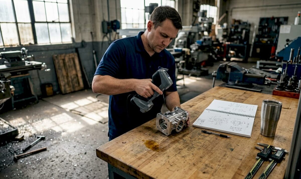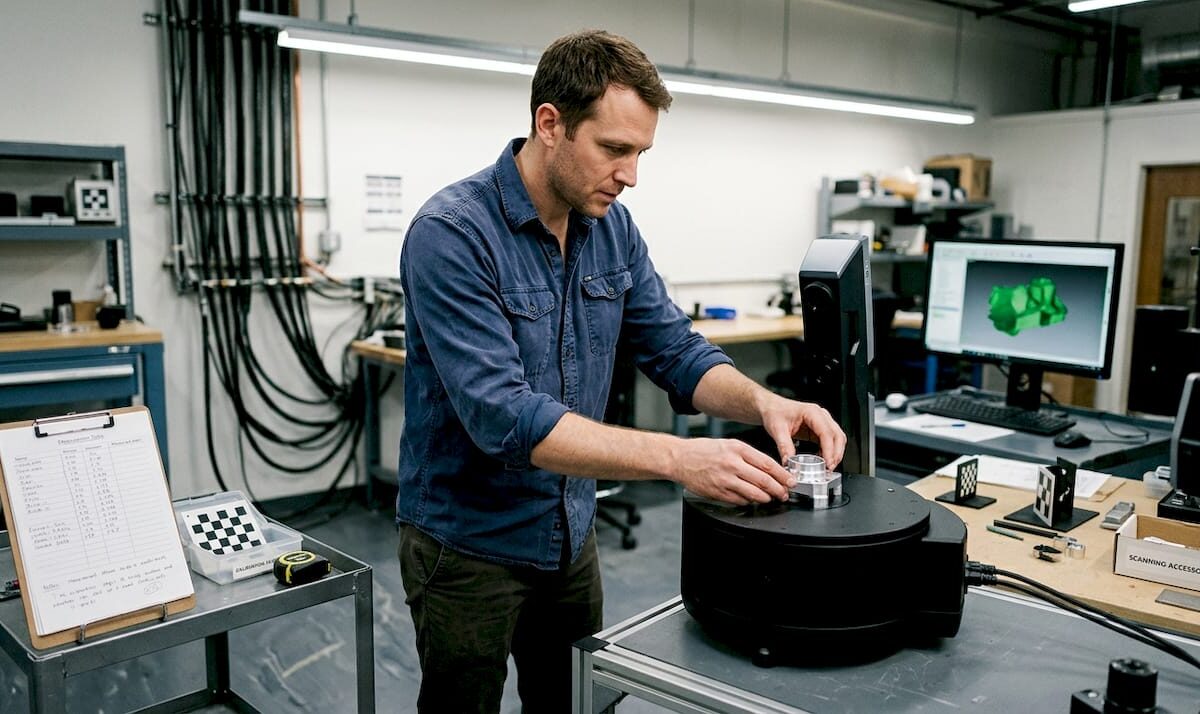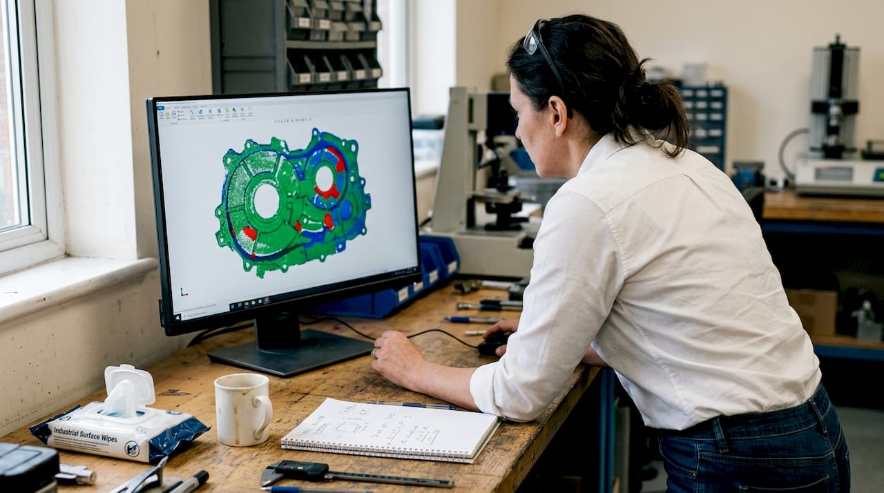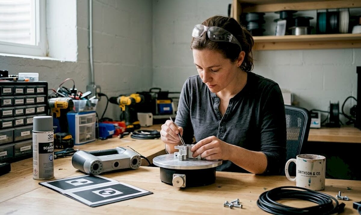
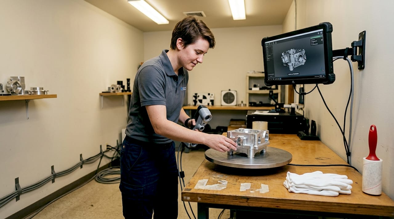
Technician setting up 3D scanning workspace

How to scan objects for 3D printing: accurate steps


TL;DR:

  • Precise scanning requires proper equipment, environment, and preparation to avoid errors.
  • Post-processing and environment control are critical for achieving accurate, printable 3D models.
  • Expert support enhances consistency and quality in complex scan-to-print workflows.

Imagine delivering a prototype to a client only to discover it fits 0.3 mm off because the original scan drifted during capture. That single error can mean scrapped parts, missed deadlines, and a project budget that spirals fast. For product developers and engineers working with physical references, the gap between a rough scan and a precise, print-ready model is where most time gets lost. This guide walks you through every stage of the scan-to-print workflow, from choosing the right scanner to fixing mesh errors before your file ever touches a printer, so you can stop guessing and start shipping accurate parts.

Table of Contents

Key Takeaways

Point Details
Choose the right scanner Structured light and laser scanners deliver sub-0.1 mm precision for prototypes, while photogrammetry is suitable for large or textured parts.
Prep surfaces meticulously Using matte spray on challenging materials boosts scan accuracy and reliability significantly.
Follow a structured workflow Careful calibration, multi-angle coverage, and steady capture prevent tracking loss and ensure clean scan data.
Fix and convert mesh for printing Cleaning, aligning, and exporting the mesh as watertight STL or converting to CAD solids is essential before 3D printing.

Essential equipment and prerequisites for 3D scanning

Before you place a single object on a turntable, understanding your scanner options saves you from buying tools that don’t match your tolerance requirements.

Three primary methodologies cover the majority of professional use cases: structured light scanning, laser triangulation, and photogrammetry. Each one has a different cost profile, accuracy ceiling, and ideal application.

Method Typical accuracy Best use case Approx. cost range
Structured light ±0.01 to ±0.05 mm Small, high-detail parts $5,000 to $50,000+
Laser triangulation ±0.04 to ±0.15 mm Mid-size industrial parts $3,000 to $30,000
Photogrammetry ±0.1 to ±1.0 mm Large objects, low budget $200 to $5,000

Industrial benchmark data confirms that portable handheld units and desktop scanners occupy very different accuracy tiers, and choosing between them depends entirely on your part size and tolerance spec.

Beyond the scanner itself, you need a short list of supporting tools:

  • Matte scan spray or powder for reflective or dark surfaces
  • Calibration targets or panels supplied by your scanner manufacturer
  • Motorized turntable for consistent multi-angle desktop captures
  • Compatible scan software such as VXelements, Artec Studio, or Meshlab
  • Stable platform free from vibration (rubber-padded table or anti-vibration mat)

Workspace setup matters as much as hardware. Fluorescent overhead lighting creates inconsistent shadows, so diffuse LED panels or softboxes give you repeatable illumination. A high-quality scan process also demands that scanner software and your workstation GPU are matched, since processing dense point clouds in real time is computationally demanding.

Pro Tip: Always verify software compatibility before purchasing a scanner. Some units lock you into proprietary platforms that limit your export options later.

Preparing objects and environment for accurate scans

Once you have the right gear, precise preparation is critical. Skipping prep is the single most common reason engineers get misaligned or incomplete scan data.

Follow this preparation sequence before every scan session:

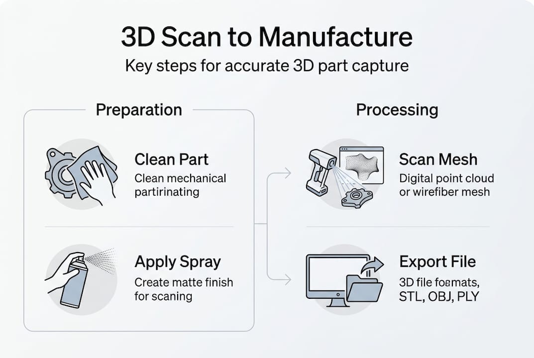
  • Clean the part thoroughly. Dust, oils, and residue create false surface details that corrupt mesh geometry.
  • Assess the surface finish. Shiny, dark, or featureless surfaces need treatment before scanning begins.
  • Apply matte spray where needed. Matte spray is crucial for reflective, dark, or featureless objects because it diffuses light and adds trackable texture the scanner’s algorithms can lock onto.
  • Place tracking markers. Adhesive dot markers help handheld scanners maintain registration across large or low-feature surfaces.
  • Position the object at waist height. Awkward angles during scanning introduce operator-induced motion blur.

Environmental habits deserve equal attention. Avoid scanning near windows where sunlight shifts during a session. Direct sun introduces infrared interference that confuses structured light and laser sensors. Keep ambient temperature stable because thermal expansion on metal parts can introduce measurable dimensional drift over a long session.

Proper calibration and controlled lighting are non-negotiable for mitigating environmental variables that degrade scan quality. Run your calibration routine at the start of every session, not just at setup.
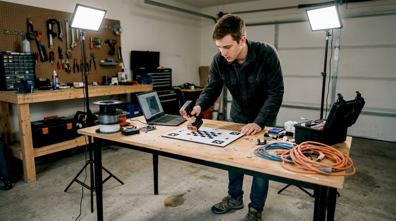
Engineer calibrates scanner under controlled lighting

For especially challenging parts, follow a step-by-step scanning guide to walk through each environmental check systematically. You can also reference the 3D scanning checklist and the design accuracy and prototyping guide to build a repeatable pre-scan protocol for your team.

Pro Tip: Prepping challenging surfaces correctly can boost first-pass scan success rates by 80 to 90%, according to professional scanning technicians. That time investment pays back immediately by eliminating re-scans.

Step-by-step scanning process for optimal results

With the setup complete, let’s break down the end-to-end scanning workflow. Skipping steps here is how tracking errors and misaligned meshes happen.

  1. Run calibration. Use the manufacturer-supplied calibration target. Never skip this, even if the scanner was calibrated yesterday.
  2. Set scan resolution and mode. Choose your target resolution based on part size and feature complexity, not maximum settings.
  3. Begin with a reference pass. Capture the dominant geometry first before moving to tight features and recesses.
  4. Maintain 30 to 60% frame overlap. Scanning with frame overlap between passes is the foundation of accurate alignment and clean mesh fusion.
  5. Pan steadily at consistent speed. Rapid movements cause motion blur; slower passes give the scanner time to lock geometry.
  6. Perform multiple passes at different angles. Top, side, and underside passes together fill in occlusions that a single sweep misses.
  7. Review the point cloud in real time. Most modern scanners show live feedback; stop and re-scan if a zone looks sparse.
  8. Export the aligned scan. For direct 3D printing, STL is suitable for replica output; for parametric engineering edits, you need a CAD solid.
Issue Likely cause Fix
Tracking loss Too-fast movement or featureless surface Slow down, add markers
Mesh holes Occlusion from single-angle pass Add underside and angled passes
Misalignment Insufficient overlap Increase to 50% frame overlap
Noise/artifacts Reflective surface or ambient light Apply matte spray, reduce ambient light

For teams running production volume scans, the scanning lab overview shows how professional setups handle repeatable multi-pass workflows at scale.

Pro Tip: If tracking is lost mid-scan, return the scanner to the last well-registered zone and slowly re-establish lock before continuing. Trying to power through tracking loss creates permanent misalignment in that section.

Advanced techniques and troubleshooting challenging parts

Even with a good process, tricky surfaces can derail a scan. Certain materials and geometries require specific tactics, and knowing them in advance saves a full rescan.
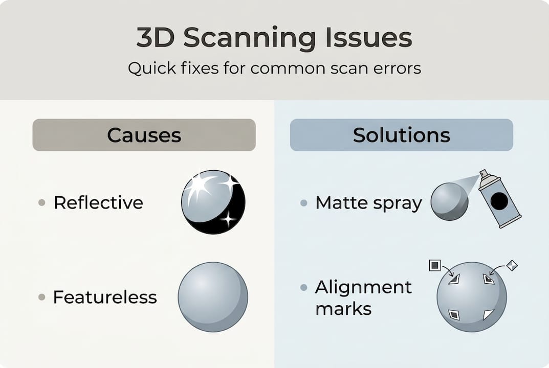
Infographic showing causes and solutions for scan issues

Reflective metals and chrome parts: Apply a thin, even coat of matte scan spray. The coating is removable and adds the texture contrast that laser and structured light sensors need to resolve geometry accurately.

Transparent or semi-transparent objects: Scan the part before final finish, or lightly scuff the surface with fine-grit media to create diffuse reflectance. Transparent surfaces return no usable data without treatment.

Dark or black parts: Different materials and surface finishes require matte spray, markers, or modified lighting to give the sensor something to track. Black absorbs near-infrared light, which is exactly what most scanners emit.

Complex internal geometry and deep recesses: You cannot capture blind holes or undercuts from a single orientation. Plan your scan order to capture recesses at oblique angles before surrounding geometry blocks access.

Tracking loss is the leading cause of scan failure. Pausing when lock degrades and overlapping back onto known geometry maintains registration far better than continuing through drift.

Failures from tracking loss are preventable with proper overlap habits. Always pause, re-establish your lock zone, then continue.

For a deeper look at how surface prep and environment interact, the achieve quality scan resource covers the full process. When your scan feeds directly into a product iteration, also review designing reliable prototypes to align your scan strategy with downstream print requirements.

Pro Tip: Always use matte spray in a well-ventilated area. Many scan sprays contain aerosol propellants and solvents that require ventilation and appropriate PPE.

Post-processing: Converting scans to printable models

Once you have scan data, refining it is crucial to get professional results. Raw point clouds are not print-ready files; they need cleaning, alignment, and export in the right format.

Here is the standard post-processing sequence:

  1. Import and align multiple scan passes. Use software like Meshlab or your scanner’s native platform to register scans to a common coordinate frame.
  2. Fuse passes into a unified mesh. Merging overlapping point clouds removes duplicate geometry and fills minor gaps.
  3. Run mesh repair. Identify and fix non-manifold edges, holes, and inverted normals that would cause print failures.
  4. Decimate intelligently. Reduce polygon count without losing critical feature detail, especially on flat surfaces where dense meshes waste file size without benefit.
  5. Export in the correct format. Choose STL or OBJ for direct printing; choose STEP or IGES when the file needs to go into a CAD environment for parametric editing.

The format choice is not cosmetic. Scan meshes must be converted to CAD solids for genuine engineering edits; direct STL prints work fine for replicas but offer no parametric flexibility.

A print-ready mesh should meet these criteria:

  • Watertight: No open boundaries or holes in the surface
  • No non-manifold edges: Every edge shared by exactly two faces
  • Correct face normals: All faces pointing outward
  • Appropriate polygon density: Balanced for file size and feature resolution

For teams that need CAD modeling services to take a scan mesh into a fully editable solid model, that process is distinct from basic STL cleanup. Review the CAD file format workflow to understand which format fits your specific pipeline before you commit to an export.

Why real-world 3D scanning is more nuanced than the manuals say

Every scanner manufacturer publishes impressive accuracy specs. What those specs rarely tell you is that they were measured under laboratory conditions that most production environments cannot replicate. Temperature fluctuations, vibration from nearby equipment, and even a vent blowing air across a part can push a scan from spec-grade to unusable.

The engineers who consistently get great results are not the ones with the most expensive scanners. They are the ones who treat environmental control as their first priority and accept that scanning is an iterative process, not a one-shot event. Hybrid approaches, where a scan establishes the base geometry and CAD modeling corrects critical tolerances, routinely outperform pure scan workflows on engineering parts.

The real-world scan accuracy insights we have gathered from actual production projects show that repeatability across sessions matters far more than peak accuracy on a single scan. A process that reliably delivers ±0.08 mm every time beats a workflow that occasionally hits ±0.03 mm but drifts unpredictably. Build a repeatable process first, then optimize for precision.

Achieve pro-level 3D scans with CC3DLabs expertise

For teams ready to streamline their scan-to-print process, expert support makes all the difference. Getting a clean, production-ready scan file consistently requires more than good equipment; it takes a calibrated workflow, trained operators, and post-processing discipline.

https://cc3dlabs.com

At CC3DLabs, our 3D scanning lab handles the full pipeline from physical object to print-ready or CAD-ready file, including professional handheld 3D scanning (accuracy to ~0.1 mm) for precise reverse engineering. Whether you need a single prototype scan or batch part documentation, we deliver high-quality scan results with fast turnaround. Our CAD modeling and reverse engineering team can take your scan mesh and rebuild it as a fully editable solid model ready for engineering changes. Request a free estimate and let us handle the precision work.

Frequently asked questions

What is the best scanner for detailed small parts?

Structured light desktop scanners are typically the best choice for small, high-detail parts, delivering accuracy as fine as ±0.01 to ±0.05 mm. Their controlled projection patterns resolve tight features that handheld units can miss.

How do I scan shiny or transparent objects accurately?

Apply matte scan spray to diffuse the surface and use angled or dome lighting to reduce reflections. For transparent parts, scan before final finish or lightly scuff the surface to create diffuse reflectance.

Can I 3D print directly from scanned meshes?

Yes, if the mesh is watertight and error-free you can print directly. However, convert to a CAD solid when you need engineering edits or parametric design flexibility that STL cannot support.

What is the typical accuracy of handheld laser scanners for industrial parts?

Handheld laser scanners typically reach accuracy levels of ±0.04 to ±0.15 mm, which covers the majority of prototyping and spare part replacement needs without requiring a fixed desktop setup.

Engineer preparing prototype for 3D scanning

3D Scanning Checklist: Ensure Accurate Prototypes & Parts


TL;DR:

  • Proper planning, environmental prep, and validation are essential to ensure accurate 3D scans.
  • Selecting the right scanner depends on part size, detail needed, and surface properties.
  • Rushing steps or skipping validation increases costly errors despite hardware quality.

One missed step in a 3D scanning workflow can send a prototype back to square one. For product developers and engineers, that means wasted hours, rework costs, and delayed production timelines. A structured checklist is not a bureaucratic formality; it is the difference between a scan you can trust and one that looks fine until the part fails tolerance checks on the shop floor. This guide walks through every critical phase: setting objectives, choosing the right scanner, preparing your environment, executing the scan, and validating results with objective metrics. Follow it consistently, and you will eliminate the most common sources of scanning error before they become expensive problems.

Table of Contents

Key Takeaways

Point Details
Define scanning requirements Clear goals and part specs are essential for selecting methods and validation metrics.
Match scanner to project Choose equipment based on part size and complexity for the highest accuracy.
Control prep and setup Careful part and environment preparation dramatically reduces errors and rescans.
Validate with metrics Use CF3D%, MD3D, and SQI3D to objectively confirm scan quality before moving to production.
Checklists prevent failures Following a robust checklist is more effective than relying solely on expensive scanners.

Set clear objectives and scan requirements

Every reliable 3D scan starts before you touch any hardware. The first step is defining exactly what you need the scan to accomplish, because that decision shapes every choice that follows.

Start by identifying the end use. A scan intended for a concept prototype has very different accuracy requirements than one destined for a production-ready part or a reverse-engineering workflow. Confusing these two contexts is one of the fastest ways to waste a scanning session.

Document the following before you begin:

  1. Part material and surface finish (matte, glossy, translucent, or metallic surfaces each require different handling)
  2. Overall dimensions and geometric complexity (simple prismatic parts versus freeform organic geometry)
  3. Required dimensional tolerance (what deviation is acceptable in millimeters or microns?)
  4. Downstream use (CAD comparison, mesh-to-print, inspection report, or reverse engineering)
  5. Deliverable format (STL, OBJ, STEP, or point cloud)

These five data points define your success criteria upfront. Without them, you are scanning blind.

Once you have your requirements documented, tie them to quantitative metrics. Quantitative metrics for 3D scanning research confirms you should always validate with Coverage Factor (CF3D%), Mean Distance (MD3D), and Scan Quality Index (SQI3D). CF3D% measures how much of the target surface your scan actually captured. MD3D quantifies the average deviation between your scan and the reference geometry. SQI3D combines multiple quality indicators into a single score for fast pass/fail decisions.

“Metric-based validation removes guesswork from the quality assessment process and creates a repeatable standard your entire team can apply.”

Setting these thresholds before the scan begins means you have an objective target to hit, not just a visual impression to judge. Understanding design accuracy and prototyping requirements is the foundation that makes every downstream decision faster and more defensible.

Pro Tip: Write your tolerance and metric thresholds directly on your scan request form. When multiple engineers are involved, this single habit eliminates the most common source of miscommunication between scanning and design teams.

Choose the right scanner and scanning method

With clear requirements in hand, the next step is selecting a scanner and scanning approach that fits those needs precisely. The wrong scanner type is not just a minor inconvenience; it can make it physically impossible to meet your documented tolerance requirements.

Here is a breakdown of the three most common scanner types used in engineering and product development:

  • Handheld laser scanners: Best for medium to large parts, complex assemblies, and on-site scanning. They offer flexibility and portability but typically deliver accuracy in the 0.05 to 0.1 mm range. Handheld laser scanners excel for prototypes up to 10 meters, while structured light scanners are the better choice for small, detailed parts.
  • Structured light scanners: Best for small to medium parts requiring high detail and tight tolerances. They project a pattern of light onto the surface and calculate geometry from the distortion. Accuracy can reach 0.01 mm or better, but they require a controlled environment and a stationary setup.
  • Photogrammetry: Best for very large objects or when portability is the priority. It uses overlapping photographs to reconstruct geometry. Accuracy is lower than laser or structured light methods, but it scales well and requires minimal equipment.

Matching the scanner to the part is not just about size. Consider these factors:

  • Surface reflectivity: Shiny or dark surfaces defeat most laser systems without preparation.
  • Feature size: Fine threads, sharp edges, or thin walls need structured light resolution.
  • Scan environment: Outdoor or production-floor scanning favors handheld systems.
  • Operator experience: Structured light systems have steeper learning curves.

Pro Tip: Do not let the scanner’s marketed accuracy spec be your only decision factor. Ask vendors for accuracy data on parts that match your geometry and surface type, not just flat reference artifacts.

If your project involves custom prototypes, understanding what makes the best print job for prototypes helps you align scanning precision with the print process you plan to use downstream. Similarly, reviewing how to choose the right printing type for production ensures your scan data will actually support the manufacturing method you intend to use.

Prepare the part and environment for scanning

Once you have the right scanner, expert results depend on methodical setup. This is the phase most engineers rush, and it is where most scan failures originate.

Follow this numbered preparation sequence every time:

  1. Clean the part thoroughly. Remove dust, oils, and loose debris. Even fine particles scatter laser light and introduce noise into the point cloud.
  2. Apply scanning spray if needed. Reflective, dark, or translucent surfaces require a temporary matte coating. Use a thin, even layer and allow it to dry completely.
  3. Secure the part with fixtures. Movement during scanning is the single biggest source of data misalignment. Use a turntable, magnetic fixture, or custom jig appropriate for the part geometry.
  4. Calibrate the scanner. Run the manufacturer’s calibration routine before every session, not just at the start of the day. Temperature changes affect optics.
  5. Set reference targets if required. Adhesive targets help the scanner track position across multiple scan passes on complex geometry.

Surface preparation and stable positioning are vital for reliable scans, and skipping either step creates problems that no amount of post-processing can fully correct.

Beyond the part itself, check these environmental factors:

  • Vibration: Isolate the scanning area from foot traffic, HVAC equipment, and nearby machinery.
  • Ambient light: Structured light scanners are sensitive to sunlight and fluorescent flicker. Use blackout curtains or scan in a dedicated room.
  • Background contrast: Place a neutral, non-reflective background behind the part to prevent the scanner from picking up stray geometry.
  • Temperature stability: Thermal expansion affects both the part and the scanner optics. Allow both to acclimate to room temperature before starting.

For a detailed look at what a controlled scanning environment looks like in practice, review our high quality 3D scan process guide. You can also explore our 3D Scanning Lab process or submit a 3D Scan Request Form to get professional support on your next project.

Technician prepping part in scanning room

Scan execution: capturing, validating, and optimizing data

With preparation complete, conducting the scan itself and validating results is where the checklist really proves its value. A clean setup does not guarantee a clean scan; you need a disciplined execution sequence.

Follow these steps in order:

  • Run an initial scan pass and review the raw mesh immediately. Do not wait until the end of the session to discover a problem area.
  • Check coverage visually and by CF3D% threshold. Any region below your target coverage percentage needs a re-scan pass before you move the part.
  • Identify and re-scan problem areas: undercuts, deep pockets, and thin walls are the most common trouble zones.
  • Align multiple scan passes using reference targets or software registration. Check alignment error before merging.
  • Export the validated mesh in the format your downstream workflow requires.

Here is a quick reference for the most common scan errors and how to address them:

Scan error Validation metric Corrective action
Missing surface coverage CF3D% below threshold Add scan passes from new angles
High deviation from reference MD3D exceeds tolerance Re-calibrate scanner, re-scan
Low overall quality score SQI3D fails Review all prep steps, repeat session
Mesh noise or spikes Visual + MD3D Reapply scanning spray, reduce ambient light
Misaligned scan passes MD3D between passes Re-register using reference targets

Validation metrics like CF3D%, MD3D, and SQI3D are essential for trustworthy scans, and applying them at each stage rather than only at the end catches errors while correction is still fast and cheap.

“A scan that passes visual inspection but fails metric validation is not a scan you can build a production part from.”

For export, use formats your CAD and manufacturing tools handle natively. Learning how to optimize workflow with CAD file formats prevents conversion errors that degrade scan accuracy. If you are newer to the terminology around scan outputs, the printing terminology for product developers guide clarifies common file type distinctions. For specialized applications like dental scanning standards, metric validation follows the same core principles but with even tighter tolerances.

Why most 3D scanning projects fail: The hidden checklist gaps

After working through hundreds of scanning projects, the pattern is clear: most failures are not hardware failures. They are process failures. The scanner was adequate. The operator was experienced. But someone skipped a step.

The three most common hidden gaps are rushing the setup phase, skipping metric validation in favor of visual approval, and assuming the scanner is inherently accurate enough without confirming it against your specific part geometry. Each of these feels like a time-saving shortcut in the moment and becomes a costly rework cycle later.

Skipped validation is a leading source of downstream part defects, and it is almost always avoidable. A five-minute metric check at the end of a scan session is far cheaper than discovering dimensional errors after a part has been printed or machined.

The uncomfortable truth is that a disciplined checklist on a mid-range scanner outperforms an ad-hoc process on a top-tier system every time. Hardware does not compensate for skipped steps. If you want to build a scanning workflow your team can trust, start with achieving high quality scans as your process baseline, then layer in metric validation as a non-negotiable exit criterion for every session.

Ready to streamline your 3D scanning workflow?

If your team is ready to move from ad-hoc scanning to a repeatable, validated process, CC 3D Labs is set up to support exactly that. We offer professional handheld 3D scanning (accuracy to ~0.1 mm), full prototyping, and expert guidance for product developers and engineers who need results they can build on.

https://cc3dlabs.com

Explore our 3D Scanning Lab services to see how we handle complex parts and tight tolerances. If your project needs both scanning and production, our full 3D printing services keep everything under one roof. And if you want to go deeper on best practices before you start, our high quality scan guide is the right next read. Get a free estimate and let us help you get it right the first time.

Frequently asked questions

What are the most important metrics for validating a 3D scan?

The key metrics are Coverage Factor (CF3D%), Mean Distance (MD3D), and Scan Quality Index (SQI3D). These three validation metrics quantify how complete and accurate your scan data is, giving you an objective pass/fail standard.

How do you select the right scanner for a specific part?

Base your choice on part size and required detail level. Scanner selection should match part size and complexity, with handheld lasers for larger prototypes, structured light for small intricate parts, and always confirm results with metric validation.

Why is environmental preparation important for 3D scanning?

Unstable or contaminated environments introduce noise, reflections, and misalignment errors that degrade scan accuracy. Surface and environmental prep is crucial for correct scans, and no post-processing step can fully recover data lost to a poor setup.

What mistakes commonly lead to poor scan quality?

Skipping preparation or validation reduces scan quality more than any hardware limitation. Using a mismatched scanner type for the part geometry is the third most frequent cause of rework.

How can engineers streamline 3D scanning workflows?

Standardize your setup sequence, define metric thresholds before each session, and treat the checklist as a non-negotiable process step. Detailed checklists and metric validation streamline workflows by catching errors early, when correction is fast and inexpensive.

Engineer scanning metal part at workbench

Unlock 3D scanning: boost design accuracy and prototyping


TL;DR:

  • 3D scanning provides precise digital models, faster prototyping, and reliable quality control.
  • Choosing the right technology depends on accuracy, object size, surface, and budget.
  • Integrating 3D scanning early improves design accuracy, reduces errors, and accelerates workflows.

3D scanning gets dismissed as a glorified copy machine for 3D printing. That misunderstanding costs product teams weeks of rework and thousands in avoidable errors. In reality, 3D scanning is one of the most powerful tools available for businesses that need precise digital models, faster prototyping cycles, and reliable quality control. This guide walks you through how 3D scanning works, the main technologies available, the real business benefits, and how to integrate scan data into your design and manufacturing workflows without the common pitfalls.

Table of Contents

Key Takeaways

Point Details
3D scanning basics 3D scanning transforms real objects into accurate digital models for design and prototyping.
Top technologies Laser triangulation, structured light, and photogrammetry each suit different accuracy and use-case needs.
Business benefits 3D scanning saves time, reduces errors, and enables rapid iteration in product development and manufacturing.
Workflow integration Scanned data seamlessly fits into CAD and production pipelines, connecting design with manufacturing.
Real-world success tips Preparation, surface treatment, and calibration improve scan quality and project success.

How 3D scanning works: The basics explained

At its core, 3D scanning captures the exact geometry and surface details of a physical object and converts that data into a digital model. That model can then be edited, analyzed, reproduced, or fed directly into a CAD (computer-aided design) system. The process has three main stages: data capture, point cloud creation, and mesh or model generation.

During data capture, the scanner emits light, laser beams, or uses cameras to measure the surface of an object from multiple angles. Each measurement records the position of a point in 3D space. Thousands or even millions of these points combine to form a point cloud, which is essentially a dense map of the object’s surface geometry. That point cloud is then processed into a mesh, a connected surface made of triangles, which becomes the usable 3D model.

The three most common scanning technologies are:

  • Laser triangulation: Projects a laser line or point onto the surface; a sensor reads the reflected angle to calculate position. Laser triangulation is highly accurate for short-range work and fine detail.
  • Structured light: Projects a pattern of light (often stripes) onto the object and uses cameras to measure how the pattern deforms across the surface. Fast and excellent for medium-sized parts.
  • Photogrammetry: Uses overlapping photographs taken from different angles to reconstruct a 3D model mathematically. Cost-effective and scalable for larger objects.

Learning how 3D scanning optimizes workflows early in a project helps teams avoid costly design revisions later.

Pro Tip: Lighting and object positioning matter more than most people expect. Consistent, diffused lighting reduces shadows and surface noise, which directly improves point cloud density and model accuracy.

A poorly set up scan environment can introduce errors that ripple through every downstream step, from CAD modeling to final part inspection. Investing 15 minutes in proper setup saves hours of cleanup.

Main types of 3D scanning technologies compared

Now that you know the basics, let’s compare the main 3D scanning techniques so you can match the right tool to your project.

Choosing the wrong scanning method is one of the most common mistakes product teams make. Each technology has a distinct performance profile depending on accuracy needs, object size, surface type, and budget.

Technology Accuracy Speed Cost Best for
Laser triangulation Very high Moderate Medium-high Small parts, fine detail
Structured light High Fast Medium Mid-size parts, smooth surfaces
Photogrammetry Moderate Slow Low Large objects, outdoor use
CT scanning Extremely high Slow Very high Internal geometry, medical

Here is a simple process for matching your scanning method to your application:

  1. Define your accuracy requirement. Engineering tolerances under 0.05mm demand laser triangulation or CT scanning.
  2. Assess your object size. Larger objects favor photogrammetry or structured light; small precision parts favor laser-based methods.
  3. Evaluate the surface. Reflective or dark surfaces need special preparation regardless of technology.
  4. Set your budget. Photogrammetry is the most accessible entry point; CT scanning is reserved for high-value inspection needs.
  5. Consider turnaround time. Structured light scanning is typically the fastest for medium-complexity parts.

Understanding the key 3D scanning techniques available helps you ask better questions when working with a scanning service provider.

Pro Tip: For highly detailed engineering parts or small components, laser triangulation consistently delivers the best results. It is the standard choice for high-accuracy work where tolerances are tight and repeatability is critical.

Key benefits for product development and manufacturing

With the options in mind, let’s look at the real business benefits of integrating 3D scanning into your development process.

The most immediate gain is the elimination of manual measurement. Traditional calipers and coordinate measuring machines (CMMs) are slow, operator-dependent, and limited in the complexity of geometry they can capture. 3D scanning captures the full surface of a part in minutes, with far less human error involved.

Designer measuring prototype with digital calipers

Workflow factor Traditional method 3D scanning method
Measurement time (medium part) 2 to 4 hours 15 to 45 minutes
Error rate Higher (operator-dependent) Significantly lower
Geometry complexity handled Limited Full freeform surfaces
Iteration speed Slow Fast
Documentation quality Manual records Full digital archive

The real-world impact spans multiple business functions:

  • Part design: Capture existing components with no original CAD file and rebuild them accurately.
  • Reverse engineering: 3D scanning significantly increases accuracy in reverse engineering and prototyping, reducing guesswork entirely.
  • Quality control: Compare scanned production parts against the original CAD model to catch deviations before they become costly defects.
  • Tooling verification: Confirm that molds and fixtures match design intent before committing to full production runs.

Teams focused on ensuring 3D scan quality for manufacturing report faster iteration cycles and fewer engineering change orders. For businesses doing reverse engineering with 3D scanning, the ability to digitize legacy parts without original drawings is a significant competitive advantage.

The compounding effect is real. Fewer errors early in development mean fewer corrections late, which directly reduces cost per prototype and shortens time to market.

From scan to workflow: Where and how 3D data is used

Understanding the benefits, let’s explore where 3D scan data delivers real impact in business workflows.

A raw point cloud is useful, but its true value comes when it is converted into a workable CAD model. Most professional scanning workflows use software like Geomagic, Artec Studio, or SOLIDWORKS to process the point cloud into a clean mesh, then into a parametric CAD file that designers can modify and manufacture from.

Here are the most common ways businesses use 3D scan data:

  • Reverse engineering: Recreate parts with no existing drawings, especially for legacy components or competitor benchmarking.
  • Quality inspection: Overlay the scan against the original CAD model to produce a color deviation map showing where parts are out of tolerance.
  • Tooling and fixture verification: Confirm that production tooling matches design specifications before first-article inspection.
  • Archiving: Build a permanent digital record of physical assets, molds, or prototypes for future reference.
  • Design iteration: Scan a physical prototype, bring it into CAD, refine it, and print or machine the next version faster.

“Modern 3D scanning streamlines the full development pipeline for new and legacy products, reducing the gap between physical reality and digital design intent.”

Exploring 3D scanning in CAD workflows shows just how tightly scanning integrates with modern design tools. Teams that understand using 3D scan data in CAD can move from physical object to production-ready file in a fraction of the time traditional methods require.

The key insight is timing. Scanning should not be an afterthought reserved for inspection. Integrating it early, at the concept and first-prototype stage, is where the biggest gains in speed and accuracy happen.

Common challenges and tips for getting reliable 3D scans

To wrap up the core guide, let’s address the most common snags and how smart teams get reliable results consistently.

Even with good equipment, scan quality can suffer if preparation and technique are not right. Surface type and environment directly influence scan accuracy, and skipping preparation steps is the fastest way to produce unusable data.

The most common challenges and how to address them:

  • Reflective surfaces: Shiny metals and plastics scatter laser or structured light unpredictably. Apply a temporary matte scanning spray to create a uniform, readable surface.
  • Dark or black surfaces: These absorb light rather than reflecting it, creating data gaps. Scanning spray also solves this problem in most cases.
  • Object movement: Even small vibrations during a scan introduce misalignment. Use a stable fixture or turntable to hold the part securely.
  • File misalignment: When combining multiple scan passes, poor alignment creates visible seams in the mesh. Use reference markers (small adhesive targets) placed on the object before scanning to give the software fixed registration points.
  • Calibration drift: Scanners can drift out of calibration over time or with temperature changes. Always run a calibration check before a critical scan session.

Pro Tip: For complex objects that require multiple scan passes, place reference markers on the object before you start. These give the alignment software fixed anchor points, which dramatically reduces mesh errors and cleanup time afterward.

Visit our tips for high quality 3D scanning resource for a deeper breakdown of preparation and post-processing best practices. Proper technique at the scan stage protects every hour of CAD work that follows.

Our take: Why mastering 3D scanning drives real innovation

Most conversations about 3D scanning focus on speed and cost savings. Those are real, but they are not the most important part of the story.

What we see consistently at CC 3D Labs is that businesses which integrate scanning early in their process do not just move faster. They think differently. When your team can digitize any physical object in minutes and bring it into a shared CAD environment, the collaboration between designers, engineers, and production teams changes fundamentally. Decisions get made with real geometry, not assumptions.

The conventional wisdom treats scanning as a QC or reverse engineering tool used after design is mostly done. That is backwards. The teams that leapfrog competitors use real-world 3D scanning insights to inform design from the very first prototype. They catch fit and function issues in the digital model before a single part is machined or molded.

The future of product development is agile, and agility requires closing the loop between physical and digital as fast as possible. 3D scanning is the bridge. Mastering it is not a technical upgrade. It is a strategic one.

Level up your workflow with CC3DLabs 3D scanning and printing solutions

Ready to put these insights into action for your business?

https://cc3dlabs.com

CC 3D Labs offers professional handheld 3D scanning (accuracy to ~0.1 mm) services paired with end-to-end CAD modeling and pro-level 3D printing for product developers and manufacturers near Philadelphia and beyond. Whether you need to digitize a legacy part, verify a production run, or accelerate your prototyping cycle, our team handles the full workflow from scan to finished part. Browse our CAD project gallery to see real examples of scan-to-print projects, or request a free estimate to get started on your next build.

Frequently asked questions

What is 3D scanning used for in business?

Businesses use 3D scanning for design accuracy, prototyping, reverse engineering, and quality control. It significantly increases accuracy in reverse engineering and prototyping compared to manual measurement methods.

Which 3D scanning method is best for fine detail?

Laser triangulation is best for short-range, high-precision applications and is the standard choice for capturing highly detailed or small parts at engineering tolerances.

What impacts 3D scanning accuracy?

Surface reflectivity, ambient lighting, and scanner calibration are the three biggest factors. Surface type and environment require careful preparation to achieve reliable, repeatable scan results.

Can 3D scan data be edited or modified?

Yes. Scan data is processed into a mesh and then converted to a parametric CAD model, which designers can fully edit, refine, and adapt for manufacturing or further prototyping.

Technician prepares part in 3D scanning lab

How we achieve a high quality 3D scan for manufacturing

Achieving precision in 3D scanning can transform your manufacturing workflow, but many product developers struggle with incomplete data, reflective surface challenges, and uncertainty about scan accuracy. This comprehensive guide walks you through every step of the high quality 3D scan process, from surface preparation and equipment setup to execution, troubleshooting, and verification. You’ll learn proven techniques to capture complete geometry, handle difficult materials, and validate scan quality using quantitative metrics. Whether you’re creating prototypes or functional parts, mastering these methods ensures your scans deliver the accuracy your projects demand.

Table of Contents

Key Takeaways

Point Details
Preparation boosts accuracy Thorough preparation reduces missing geometry and data noise before you scan.
Surface handling strategies Apply scanning spray to reduce reflectivity and use adhesive markers to aid alignment across passes.
Plan multi angle scans Plan scan passes from multiple angles to capture geometry with sufficient overlap for full data.
Post scan verification Evaluate scan quality with quantitative metrics to confirm completeness and reliability after data capture.

Preparing for a high quality 3D scan

Successful 3D scanning starts long before you power up the equipment. Your preparation phase determines whether you’ll capture clean, complete data or spend hours troubleshooting missing geometry and noise artifacts. Product developers who skip this stage often face repeated scans and project delays.

Start by examining your part’s material properties and surface characteristics. Reflective and black surfaces cause data loss that derails even expensive scanning equipment. Shiny metal components, glossy plastics, and dark rubber parts scatter or absorb the scanner’s light, creating gaps in your point cloud data. Document these problem areas before you begin.

Apply scanning spray to reduce reflectivity on challenging surfaces. This temporary coating creates a matte finish that allows scanners to capture accurate geometry. Choose sprays that evaporate cleanly without residue, especially for parts heading to production. For transparent or highly reflective areas, consider using adhesive markers to give the scanner tracking points. These reference dots help the software align multiple scan passes and maintain accuracy across complex geometries.

Your scanning environment matters as much as surface preparation. Control ambient lighting to prevent interference with the scanner’s projected patterns. Natural sunlight and fluorescent fixtures can introduce noise that corrupts your data. Set up in a space with consistent, diffuse lighting or use blackout conditions for optimal results. Secure your part on a stable platform that won’t shift during scanning. Even minor vibrations translate to measurement errors.

Create an equipment checklist before each session:

  • Calibrated scanner with fresh calibration verification
  • Scanning spray and application tools
  • Reference markers and adhesive
  • Stable mounting platform or turntable
  • Controlled lighting setup
  • Clean lens and projection surfaces

Pro Tip: Test your setup on a simple geometric shape before scanning complex parts. A calibration cube or cylinder helps you verify that your preparation steps are working and your scanner is performing within specification.

Our 3D scanning lab handles these preparation challenges daily, ensuring every scan starts with optimized conditions for maximum accuracy.

Executing the 3D scan: step by step instructions

With preparation complete, you’re ready to capture high quality scan data. The execution phase requires methodical technique and attention to scanner settings. Rushing through this process guarantees you’ll need to rescan, wasting time and potentially damaging spray coated surfaces.

  1. Select your scanner type based on accuracy requirements and working environment. Portable scanners trade some accuracy for shop floor usability, while stationary systems deliver laboratory grade precision. Match the tool to your tolerance specifications and workspace constraints.
  2. Calibrate the scanner immediately before use. Temperature changes and transport can affect measurement accuracy. Run the manufacturer’s calibration routine and verify results against a known reference object. Document calibration data for quality records.
  3. Plan your scanning path to capture geometry from multiple angles. Complex parts require overlapping scan passes to ensure complete coverage. Start with broad passes to capture overall shape, then focus on detailed features like holes, edges, and fine textures. Rotate the part systematically rather than moving the scanner erratically.
  4. Adjust exposure settings for reflective surfaces. If scanning spray didn’t completely eliminate shine, reduce scanner sensitivity to prevent oversaturation. Modern scanners offer exposure bracketing that captures multiple passes at different settings, giving you clean data even on challenging materials.
  5. Switch to infrared or blue light modes when scanning metallic or highly reflective parts. Different wavelengths interact with surfaces in unique ways. Blue light often penetrates thin translucent materials better, while infrared reduces glare on polished metals. Experiment with these settings during your test scans.
  6. Monitor data quality in real time through the scanner software. Most systems display point cloud density and coverage as you work. Watch for gaps, noise clusters, or alignment errors. Address problems immediately rather than discovering them during post processing.

Pro Tip: Scan in short sessions rather than one marathon pass. This approach lets you verify data quality incrementally and adjust technique before investing hours in a flawed scan.

Statistic spotlight: Professional scanning services achieve uncertainty measurements around 41 microns on additive manufacturing artifacts, demonstrating the precision possible with proper technique.

Our 3D scanning lab uses professional handheld 3D scanners (accuracy to ~0.1 mm) and proven scanning protocols to deliver consistent, high accuracy results for manufacturing applications.

Troubleshooting common problems and verification of scan quality

Even experienced operators encounter scanning challenges. Recognizing problems early and knowing how to fix them separates successful scans from wasted effort. Your verification process must catch issues before you commit scan data to expensive manufacturing operations.

Detect missing data areas by reviewing your point cloud for gaps and sparse regions. These holes typically appear on undercuts, deep recesses, or areas where the scanner couldn’t maintain line of sight. Remediate by rescanning from different angles or using a smaller scanner head that accesses tight spaces. For persistent gaps on reflective surfaces, apply additional scanning spray and increase marker density.

Engineer checks point cloud for scan errors

Noise artifacts show up as scattered points floating away from the actual surface. This happens when ambient light interferes with the scanner or when surface properties confuse the measurement system. Clean up minor noise in post processing software, but severe artifacts require rescanning with better environmental control. Check that your lighting hasn’t changed and that no reflective objects are visible in the scanner’s field of view.

Compare scan results to original CAD models or physical measurements to validate accuracy. Import your point cloud into inspection software and run deviation analysis. Color maps instantly reveal where your scan differs from the reference geometry. Focus on critical dimensions and functional features rather than cosmetic surfaces.

Use quantitative metrics for objective quality assessment:

  • Coverage Factor: Percentage of target surface captured in scan data
  • Point density: Number of measurement points per square millimeter
  • Standard deviation: Variation in measurements across repeated scans
  • Scan Quality Index (SQI): Composite score based on completeness and noise levels
Metric Target Value Acceptable Range
Coverage Factor 98-100% 95% minimum
Point Density 50-100 pts/mm² 30 pts/mm² minimum
Standard Deviation <0.05mm <0.1mm acceptable
SQI Score 90-100 80 minimum

Understand precision limits and expected uncertainty for your scanner class. Uncertainty measurements of 41 microns represent achievable performance with industrial CT and CMM systems, but portable scanners typically operate at 50-150 micron uncertainty. Set realistic expectations based on your equipment capabilities.

Pro Tip: Create a reference artifact that matches your typical part materials and geometry. Scan it regularly to track your system’s performance over time and catch calibration drift before it affects production parts.

“Quantitative verification transforms scanning from guesswork into a controlled measurement process. Metrics give you confidence that your data meets manufacturing requirements.”

Our 3D modeling gallery showcases parts created from verified scan data, demonstrating the quality achievable with rigorous verification protocols.

Applying high quality 3D scans in manufacturing and prototyping

Accurate scan data becomes valuable only when you successfully integrate it into your manufacturing workflow. Real world applications emphasize scan accuracy as critical for functional parts and prototypes that must perform under real conditions. Understanding how to bridge scanning and production maximizes your investment in measurement technology.

Integrate scan data into CAD workflows by importing point clouds or mesh files into your design software. Modern CAD platforms offer tools to fit geometric primitives to scanned surfaces, extract cross sections, and create parametric models from measurement data. This reverse engineering process lets you modify existing parts, create replacement components, or design assemblies that interface with scanned geometry.

Prepare scan files for 3D printing or CNC manufacturing by converting point clouds to watertight mesh models. Clean up scan artifacts, fill small holes, and smooth surfaces while preserving critical dimensions. Export in formats appropriate for your manufacturing process: STL for 3D printing, STEP for CNC machining, or IGES for injection molding tool paths. Verify that file resolution matches your manufacturing tolerances without creating unnecessarily large datasets.

Infographic showing 3D scan workflow steps

Understand tolerances achievable from scan based models. Your final part accuracy depends on both scan precision and manufacturing process capabilities. A scan with 50 micron uncertainty combined with 3D printing at 100 micron layer height produces parts with approximately 150 micron total variation. Stack these tolerances appropriately when designing assemblies with multiple scanned components.

Benefits of accurate scans extend beyond dimensional correctness:

  • Reduced rework cycles by catching design issues before manufacturing
  • Faster development timelines through parallel scanning and design work
  • Improved communication with manufacturers using verified 3D data
  • Lower prototype costs by minimizing failed builds
  • Better documentation for quality control and inspection

Best practices for scanning to prototype workflow include maintaining a digital thread from initial scan through final production. Document scan parameters, verification results, and any modifications made during CAD processing. This traceability helps you troubleshoot problems and replicate successful processes. Archive raw scan data alongside processed models so you can return to original measurements if needed.

Our 3D printed prototypes service combines accurate scanning with precision manufacturing, delivering functional parts that match your specifications from initial measurement through final production.

Enhance your projects with expert 3D scanning and printing services

Mastering the high quality 3D scan process takes time, specialized equipment, and repeated practice. Many product developers find that partnering with experienced scanning professionals accelerates their projects while ensuring measurement accuracy. Professional services eliminate the learning curve and equipment investment, letting you focus on design and development.

https://cc3dlabs.com

CC 3D Labs delivers high-accuracy scanning integrated with advanced manufacturing capabilities. Our scanning experts handle surface preparation, multi-angle capture, and rigorous verification, providing you with clean, accurate data ready for immediate use. We bridge scanning and production seamlessly, offering 3D printing services that transform your scans into functional prototypes and production parts.

Whether you need 3D scanning services for reverse engineering, quality inspection, or prototype development, our Philadelphia area facility provides fast turnaround with engineering grade accuracy. We support projects from single prototype scans to batch production scanning, with options for local pickup or international shipping. Get a free online estimate and discover how professional scanning accelerates your development timeline while reducing costs.

Our 3D printed prototypes and repair parts service completes the workflow from scan to finished component, ensuring your parts meet functional requirements and manufacturing tolerances.

Frequently asked questions

What surfaces are hardest to scan and how to handle them?

Reflective metallic surfaces, glossy plastics, and black rubber materials present the greatest scanning challenges. Shiny and dark surfaces cause data loss by scattering or absorbing the scanner’s projected light patterns. Apply temporary scanning spray to create a matte coating that improves light return. Use adhesive reference markers on highly reflective areas to give the scanner tracking points. For transparent materials, consider using colored dyes or coatings that wash off after scanning.

How to verify the accuracy of a 3D scan?

Compare your scan data to original CAD models using deviation analysis software that generates color coded error maps. Measure critical dimensions on the physical part with calipers or micrometers, then verify those same features in your scan data. Empirical studies measure uncertainty around 41 microns for industrial scanning systems, providing a benchmark for expected precision. Use quantitative metrics like Coverage Factor and Scan Quality Index for objective assessment rather than relying on visual inspection alone.

What scanner type is best for shop floor use versus lab accuracy?

Portable handheld scanners offer flexibility for shop floor measurement but trade some accuracy for usability, typically achieving 50-150 micron precision. Stationary structured light or laser scanners deliver laboratory grade accuracy below 50 microns but require controlled environments and fixed setups. Select scanners using quantitative metrics that match your tolerance requirements. For functional prototypes, portable scanners often provide sufficient accuracy. For metrology and quality inspection, invest in stationary systems with verified uncertainty specifications.

How long does a typical high quality 3D scan take?

Scanning time varies dramatically based on part size, complexity, and required accuracy. Simple parts under 6 inches may scan in 15-30 minutes including setup and verification. Complex assemblies with intricate features can require 2-4 hours for complete multi-angle coverage. Factor in additional time for surface preparation, calibration, and post-processing. Professional scanning services optimize these workflows, often completing projects faster than in-house scanning due to experience and specialized equipment.