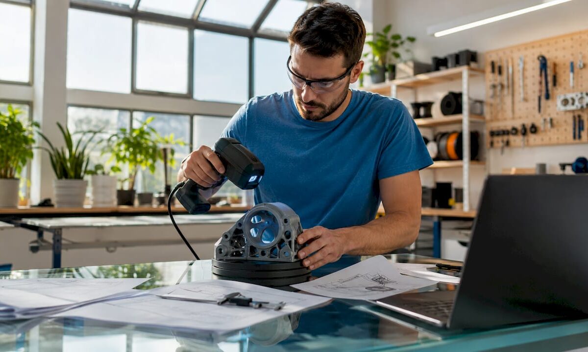
Technician 3D scanning aircraft part in workshop

Types of Industries Using 3D Scan Data: 2026 Guide


TL;DR:

  • D scan data captures precise physical geometry to improve quality, speed, and accuracy across industries. Its adoption enhances workflows in automotive, construction, healthcare, manufacturing, and cultural preservation by enabling real-time measurement and digital integration. Success depends more on software connectivity and post-processing automation than on hardware capabilities.

3D scan data is defined as the digital capture of physical geometry, converting real-world objects into precise point clouds or mesh models used for analysis, design, and production. The types of industries using 3D scan data now span automotive, aerospace, construction, healthcare, manufacturing, and cultural preservation. Each sector adopts 3D scanning, the recognized industry term for this technology, to replace slow manual measurement with full-surface digital capture. The result is faster decisions, fewer errors, and tighter tolerances across every stage of a product’s life.

CAD engineer working with 3D scan data at desk

1. Types of industries using 3D scan data: automotive and aerospace

Automotive and aerospace teams use 3D scanning for quality inspection, reverse engineering, and maintenance, repair, and overhaul (MRO). The shift from traditional coordinate measuring machines (CMMs) to handheld 3D scanners is the single biggest change in industrial metrology over the past decade.

  • Stamped part inspection: 3D scanners capture full surface geometry in minutes. CMMs measure discrete points and miss deformation patterns like springback in sheet metal.
  • Deviation maps: Real-time chromatic deviation maps show exactly where a part drifts from CAD nominal, giving production line operators immediate feedback.
  • Reverse engineering: Engineers scan legacy components with no surviving drawings and reconstruct parametric CAD models for redesign or replacement part production.
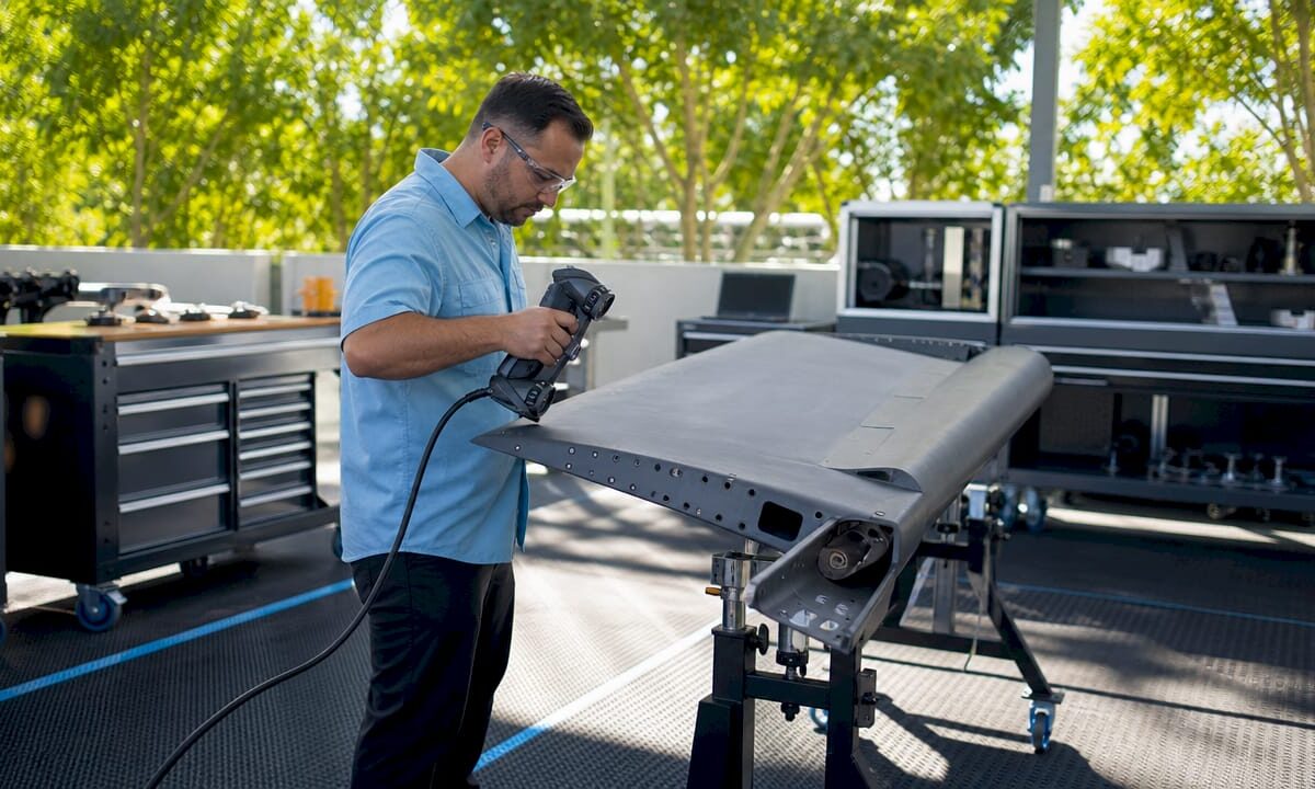
  • In-situ aerospace measurement: Aerospace scanning without disassembly captures engine inlet lip geometry at sub-0.03 mm accuracy, delivering certified digital inspection reports without pulling the engine.
  • Timeline compression: Replacing a two-month manual gauge design and build process with minutes-long 3D scanning reduces project timelines by at least 33%.

That 33% reduction is not a rounding estimate. It represents the difference between a gauge shop consuming two months of calendar time and a technician walking the shop floor with a handheld scanner the same afternoon.

Pro Tip: Before scanning stamped metal parts, apply matte reference targets to reflective surfaces. Shiny metal scatters laser light and degrades point cloud density, which forces expensive rescan sessions.

2. Architecture, construction, and facility management

Construction is one of the clearest examples of how 3D scan data benefits an entire project lifecycle, from design coordination through ongoing facility management.

3D LiDAR scanning reduces rework by up to 50% by catching clashes between mechanical, electrical, and plumbing (MEP) systems before installation begins. That number matters because rework is the single largest hidden cost in commercial construction.

How construction teams apply scan data

  1. As-built documentation: Scan the site at each major milestone and compare point clouds against the BIM model to confirm work matches design intent.
  2. Clash detection: Overlay scan data with MEP drawings to find pipe and duct conflicts before crews install anything.
  3. Renovation planning: Scan existing structures to get accurate geometry when original drawings are missing or outdated.
  4. Digital twin creation: Combine successive scans into a living model that facility managers use for space planning, maintenance scheduling, and emergency response.
  5. Quality assurance: Use scan-to-BIM comparison to generate deviation reports that satisfy owner inspection requirements.

The table below shows how scan data changes key construction metrics.

Workflow stage Traditional approach With 3D scan data
As-built verification Manual tape measure and sketches Point cloud vs. BIM comparison in hours
Clash detection 2D drawing review Automated spatial conflict flagging
Rework rate Industry baseline Reduced by up to 50%
Facility handover Paper drawings Accurate digital twin model

For teams managing large facilities, the archival scanning guide from Cc3dlabs covers how to structure scan data for long-term asset management.

3. Healthcare and medical fields

Healthcare uses 3D scanning to capture patient anatomy with a level of accuracy that traditional casting and manual measurement cannot match. Digital workflows replace casting sessions, cutting appointment time and improving fit for prosthetics and orthotics.

  • Prosthetics and orthotics: Clinicians scan residual limbs or affected anatomy, then send the mesh directly to a CAD workstation for socket design. The patient skips the plaster cast entirely.
  • Surgical planning: Surgeons import patient-specific scan data into simulation software to rehearse complex procedures on a digital replica before entering the operating room.
  • Dental and orthodontic labs: Intraoral scanners produce digital impressions that replace physical molds. Labs receive files, not trays of alginate, and produce crowns, aligners, and retainers from the digital model.
  • Bioprinting research: Scan data of tissue structures feeds into bio-printing workflows for research into custom implants and scaffolding.

Pro Tip: For prosthetic socket design, scan the contralateral limb as a symmetry reference. Designers use it to mirror geometry and reduce the number of fitting iterations the patient needs.

The speed advantage in healthcare is real. A scan session takes minutes. A traditional casting session takes 30 minutes or more, requires drying time, and still produces a static model that cannot be digitally modified.

4. Industrial manufacturing and reverse engineering

Manufacturing is where 3D scan data has its deepest roots and its most measurable financial impact. The core shift is from sampling-based CMM inspection to full surface geometry capture that reveals deformation patterns no point measurement can detect.

  • Reverse engineering: Scan a physical part, align the point cloud in CAD software, and reconstruct a parametric model. This is the standard path for legacy tooling with no surviving drawings.
  • Quality control integration: Real-time integrated scanning generates deviation maps on the production line, replacing end-of-shift inspection reports with live feedback.
  • PLM and quality system integration: The true value of 3D scanning comes from connecting scan data to PLM and CAD software, forming a digital ecosystem rather than treating the scanner as a standalone tool.
  • Post-processing management: Data alignment, mesh cleanup, and parametric CAD conversion can equal scanning time without automation. Teams that underestimate this step lose the efficiency gains they expected.

Transitioning to real-time integrated metrology reduces inspection costs by over 50% in high-precision manufacturing. Traditional inspection can account for more than half of a qualified metal component’s total production cost. That figure alone justifies the capital investment for most production managers.

For a practical breakdown of how to structure scan-to-CAD workflows, the scan to CAD workflow guide at Cc3dlabs covers the full process from raw point cloud to production-ready file. Teams dealing with industrial measurement challenges will also find that real-time scan integration directly improves process control at the machine level.

5. Cultural heritage, entertainment, and emerging fields

3D scanning extends well beyond factories and hospitals. Cultural heritage and entertainment industries use scan data to document, preserve, and recreate physical reality at a level of detail that photography cannot achieve.

  • Historic landmark preservation: Scan teams capture full building geometry before restoration work begins. If a structure is damaged, the scan record supports accurate reconstruction.
  • Museum archiving: Institutions scan artifacts to create digital records for research access, reducing physical handling of fragile objects.
  • Art restoration: Conservators use scan data to document surface condition before treatment and verify results afterward.
  • VFX and gaming: Studios scan actors, props, and environments to create photorealistic digital assets for film and game production. The scan replaces weeks of manual modeling.
  • VR and AR content: Scan-based environments give users accurate spatial context that hand-modeled scenes cannot replicate.
  • Biotech and emerging applications: Researchers scan anatomical structures to inform bio-printing and custom implant design, pushing 3D scan data into territory that did not exist as a commercial application five years ago.

The entertainment industry’s adoption of 3D scanning is a useful signal for other sectors. When a technology becomes standard practice in a field as cost-sensitive as film production, the hardware and software costs have dropped to a point where most professional organizations can justify the investment.

Key takeaways

3D scan data delivers the greatest value when integrated directly into existing CAD, PLM, and quality management systems rather than used as a standalone measurement tool.

Point Details
Automotive and aerospace lead adoption Handheld scanning cuts project timelines by at least 33% over traditional manual gauging.
Construction rework drops sharply LiDAR-based scan-to-BIM comparison reduces rework by up to 50% on commercial projects.
Healthcare replaces physical casting Digital anatomy capture speeds prosthetic design and eliminates plaster casting sessions.
Manufacturing gains real-time control Integrated scanning cuts inspection costs by over 50% by replacing batch post-process reports.
Software integration drives ROI Connecting scan data to PLM and CAD systems creates a digital ecosystem that multiplies scanner value.

What I’ve learned about 3D scan data adoption across industries

The conversation about 3D scanning almost always starts with hardware. Which scanner has the best resolution? Which one is fastest? That is the wrong question, and I have seen it derail more than a few adoption projects.

The hardware is good enough. It has been good enough for years. What separates teams that get real results from teams that buy expensive equipment and underuse it is software integration. If your scan data cannot talk to your CAD system, your PLM platform, or your quality management workflow, you have a very expensive ruler.

The second thing professionals consistently underestimate is post-processing time. Scanning a part takes minutes. Aligning the point cloud, cleaning the mesh, and converting it to a usable CAD format can take just as long without the right automation tools in place. Plan for that time before you promise your stakeholders a turnaround.

The trend I find most significant right now is real-time integrated metrology. Moving inspection from the end of a production run to the machine itself changes the economics of quality control entirely. You stop making bad parts instead of sorting them out afterward. That shift is what will push 3D scanning from a specialty tool to a standard production asset across every sector covered here.

My advice to any decision-maker evaluating 3D scanning: audit your data ecosystem first. Know exactly where scan outputs will live, who will access them, and how they connect to downstream decisions. The scanner is the easy part.

— Justin

Cc3dlabs supports your 3D scanning and production workflow

Cc3dlabs operates a professional 3D scanning lab near Philadelphia that handles professional handheld 3D scanning (accuracy to ~0.1 mm) for parts, prototypes, and complex assemblies. The lab’s outputs connect directly to CAD modeling and filament-based 3D printing, so your team moves from physical object to production-ready file without switching vendors.

https://cc3dlabs.com

Whether you need a single prototype scanned and printed or a batch production run built from scan-derived CAD data, Cc3dlabs covers the full workflow. The 3D printing services page lists current capabilities, turnaround options, and how to request a free estimate. Local pickup is available, and shipping serves clients across the country.

FAQ

What industries use 3D scan data most extensively?

Automotive, aerospace, construction, healthcare, and industrial manufacturing are the primary sectors. Each uses 3D scanning for quality control, reverse engineering, or documentation workflows that require full-surface geometry capture.

How does 3D scanning reduce construction rework?

LiDAR scanning compares physical site conditions against BIM models in real time, catching clashes and deviations before installation. This process reduces rework by up to 50% on commercial construction projects.

What is the difference between CMM inspection and 3D scanning?

CMMs measure discrete points on a surface. 3D scanning captures millions of points per second across the full surface, revealing deformation patterns and deviations that point measurements miss entirely.

How does healthcare benefit from 3D scan data?

Clinicians use scan data to design prosthetics, plan surgeries, and produce dental restorations without physical casting. Digital workflows are faster, more accurate, and produce files that labs can modify without a new patient appointment.

What should teams plan for before adopting 3D scanning?

Plan for post-processing time alongside scanning time. Data alignment, mesh cleanup, and CAD conversion require dedicated software and trained staff. Teams that skip this planning consistently underdeliver on the efficiency gains they projected.
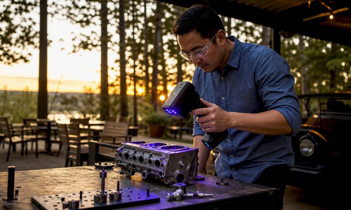
Engineer scanning a legacy car part with 3D scanner

Scanning for Legacy Part Reproduction: A 2026 Guide


TL;DR:

  • D scanning transforms physical legacy parts into detailed digital models for reproduction and inspection. It uses various methods, including structured light, laser, photogrammetry, and CT scanning, depending on the required accuracy and internal complexity. Proper workflow integration and documentation are essential to qualify reproduced parts in regulated industries and maximize the value of scan data.

3D scanning is the foundational step in legacy part reproduction, converting physical components into accurate digital models that engineers can inspect, modify, and manufacture from. The process, formally called reverse engineering through digitization, captures geometry down to fractions of a millimeter. This makes it possible to reproduce parts that have no surviving drawings, no original CAD files, and no active supplier. The role of scanning in legacy part reproduction goes beyond simple copying. It creates a verified digital record that supports future redesign, quality inspection, and regulatory traceability.

What scanning technologies are used in legacy part reproduction?

Four primary technologies drive 3D scanning in reproduction workflows: structured light scanning, laser scanning, photogrammetry, and industrial Computed Tomography (CT) scanning. Each method captures different types of geometry with different levels of accuracy and cost.

Structured light scanners project a grid pattern onto a surface and measure how the pattern deforms. This method captures external geometry with high resolution and works well for machined metal parts, housings, and connectors. Laser scanning uses a similar principle but projects a laser line instead of a grid, making it effective for larger parts and freeform surfaces.

High-resolution photogrammetry offers non-invasive, accurate 3D documentation that preserves surface details with minimal human intervention. It works by processing overlapping photographs through algorithmic pipelines. Photogrammetry is best suited for capturing texture and surface character rather than tight mechanical tolerances.

Industrial CT scanning stands apart from the other three methods. CT scanning generates non-destructive 3D volumetric models that reveal internal features, hidden cavities, and wall thicknesses without disassembling or damaging the original part. This makes CT the only viable option when internal geometry drives the function of the component.

Technology Best for Accuracy Key limitation
Structured light External surfaces, small parts Very high Limited to line of sight
Laser scanning Large parts, freeform surfaces High Surface reflectivity issues
Photogrammetry Texture, surface character Moderate Lower dimensional accuracy
Industrial CT Internal features, assemblies Very high High cost, slow throughput

Pro Tip: For parts with both complex external geometry and critical internal channels, combine structured light scanning for the exterior with CT scanning for internal features. This gives you a complete digital model without destroying the original part.

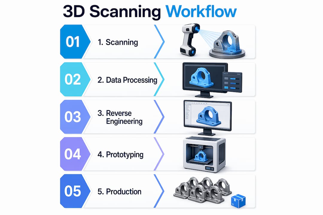
Infographic illustrating 3D scanning process steps

How does scanning integrate into the reverse engineering workflow?

Scanning is one step inside a larger reverse engineering process. Getting that step right requires a structured approach from the moment the physical part arrives.

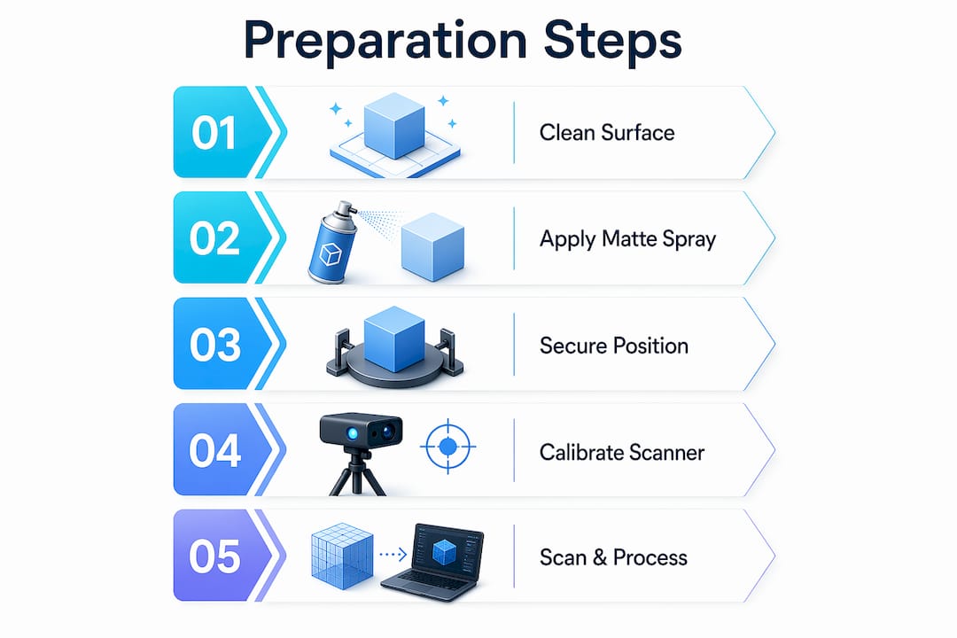
  1. Initial assessment. Examine the part for damage, wear, and surface condition. Identify which features are functional and which are cosmetic. This determines which scanning method to use and where to focus resolution.
  2. Scan execution. Set up the scanner according to part size, material reflectivity, and required accuracy. For shiny metal surfaces, apply a temporary matte spray to reduce noise. Capture multiple passes to cover all angles.
  3. Data processing. Raw scan data often contains noise and incomplete surfaces. Dedicated software such as Geomagic Design X or Artec Studio processes the point cloud into a clean mesh. Skilled operators are required at this stage. Version control of scan files starts here.
  4. CAD reconstruction. Convert the mesh into a parametric CAD model using tools like SolidWorks or CATIA. This step requires engineering judgment, not just geometry tracing. The engineer must decide which features are nominal and which reflect wear or damage.
  5. Validation. Compare the reconstructed CAD model against the original scan data. Deviation maps highlight where the model diverges from the physical part. Acceptable tolerances depend on the application.

Pro Tip: Document engineering intent at every step. Note why a feature was modeled a certain way, especially when the physical part shows wear. That reasoning becomes part of the evidence chain needed for qualification in regulated industries.

Establishing a traceable qualification workflow that links part assessment, material identification, and scan data version control is the defining challenge in regulated sectors. Aerospace, defense, and medical manufacturers cannot simply reproduce geometry. They must prove the reproduction meets the original performance standard.

What are the benefits and challenges of 3D scanning for legacy parts?

The benefits of part scanning are concrete and measurable. professional handheld 3D scanning (accuracy to ~0.1 mm) captures accurate, watertight geometry,, capturing fine surface details and complex mechanical interfaces that manual measurement cannot reliably document. That level of accuracy eliminates the guesswork that comes with calipers and hand sketches.

Key benefits include:

  • Geometry capture without contact. Scanning preserves fragile or worn parts during the documentation process.
  • Speed. A structured light scanner can capture a full part surface in minutes. Manual measurement of the same part could take hours.
  • Complex feature documentation. Freeform surfaces, compound curves, and organic shapes that are impossible to measure manually are captured completely.
  • Digital twin creation. The scan becomes a permanent digital record for future inspection, redesign, or reproduction.

The challenges are equally real. Many reverse engineering projects stall because teams treat the work as a scanning task rather than a full data, compliance, and workflow integration effort. Geometry capture is necessary but not sufficient.

Specific challenges engineers face:

  • Data volume. High-resolution scans generate large point cloud files that require significant computing resources and organized storage.
  • Engineering intent. A scan captures what the part looks like now, not what it was designed to be. Worn features, corrosion, and deformation all appear in the scan data.
  • Material validation. Additive manufacturing material behavior differs from original manufacturing methods. Geometry matching alone does not qualify a reproduced part for service.
  • Audit trails. Regulated industries require documented evidence chains linking every decision from scan to final part.

Pro Tip: Build your evidence chain from day one. Log the scan date, operator, equipment calibration record, software version, and every processing decision. Retrofitting this documentation after the fact is expensive and often incomplete.

How do manufacturers apply scanning in practical production workflows?

The practical applications of digitization for legacy parts extend well beyond creating a one-time reproduction. Manufacturers use scan data across multiple production and maintenance scenarios.

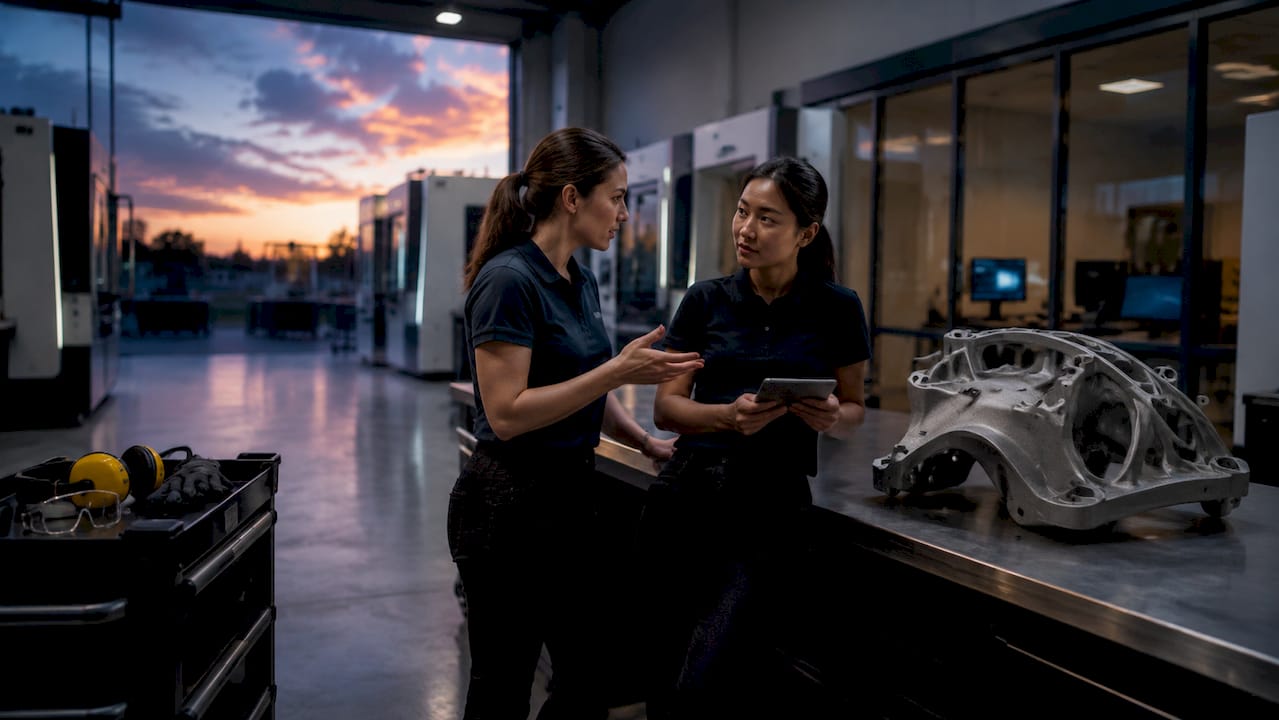
Technicians discussing 3D printed spare part on factory floor

High-fidelity scanning combined with additive manufacturing connects classical part geometry with modern digital production methods. A scanned digital twin can feed directly into a 3D printer for rapid prototyping, or into a CNC machining center for subtractive production. The same scan data supports both paths, which reduces lead time when a manufacturer needs to evaluate multiple production options quickly.

You can also use scan-derived digital twins for design accuracy and prototyping improvements. Engineers overlay the scan of a worn part against the original CAD model to measure how the part has changed in service. This data informs redesign decisions and helps predict future failure modes.

Application Scanning input Outcome
Spare part reproduction Full surface scan Replacement part manufactured to original geometry
Wear analysis Scan vs. nominal CAD Quantified deviation map for maintenance planning
Rapid prototyping Scan to mesh to print Physical prototype in hours for fit and function testing
Aftermarket servicing Scan of discontinued part New supplier tooling created without original drawings
Quality inspection Scan of produced part Automated comparison against design intent

Aftermarket and legacy vehicle servicing represent one of the highest-value applications. When a manufacturer discontinues a component and the original tooling no longer exists, a high quality 3D scan of a surviving example becomes the only path to reproduction. This is common in aerospace MRO (maintenance, repair, and overhaul), classic vehicle restoration, and industrial equipment servicing.

The production efficiency gains are direct. Eliminating manual measurement and manual redrawing removes two of the most error-prone steps in legacy part reproduction. Scan data feeds manufacturing equipment directly, which reduces the number of iterations needed to achieve a conforming part.

Key Takeaways

Scanning is the critical first step in legacy part reproduction, but traceable workflow integration, material validation, and engineering documentation determine whether a reproduced part qualifies for service.

Point Details
Scanning precision matters professional handheld scanners capture geometry to roughly 0.05–0.1 mm (50–100 microns), far beyond manual measurement capability.
Technology selection is part-specific CT scanning is required for internal features; structured light works best for external surfaces.
Workflow integration is non-negotiable Reverse engineering projects fail when teams treat scanning as the only task rather than one step in a documented process.
Material validation is separate from geometry A geometrically accurate scan does not automatically qualify a reproduced part, especially in regulated industries.
Digital twins extend value beyond reproduction Scan data supports wear analysis, quality inspection, and future redesign, not just one-time part replication.

Why scanning alone will not save your legacy part program

Most manufacturers I work with come to scanning with the right instinct but the wrong expectation. They assume that once the scan is done, the hard part is over. The opposite is true.

The scan gives you geometry. What it does not give you is engineering intent, material specification, or a qualification record. A worn part scanned at high accuracy still gives you a worn part. The engineer has to decide which dimensions represent the design and which represent 40 years of service. That judgment call is not in the scan file.

The manufacturers who succeed with legacy reproduction treat the scan as the beginning of a documented evidence chain, not the end of a measurement task. They track every decision, every software version, and every material substitution. In aerospace and defense, that chain is what gets a part approved. In commercial manufacturing, it is what prevents a costly recall.

The shift I see in 2026 is toward combined workflows where scanning, CAD reconstruction, additive manufacturing, and inspection all share the same data thread. Tools like Authentise and similar manufacturing execution platforms are making this more accessible. But the discipline of documentation still comes from the engineering team, not the software. If you are starting a legacy part program, build the process before you buy the scanner.

— Justin

Cc3dlabs scanning and reproduction services for legacy parts

Cc3dlabs operates a professional 3D scanning lab near Philadelphia that supports manufacturers, engineers, and product developers with professional handheld 3D scanning (accuracy to ~0.1 mm) and scan-to-CAD processing. The team handles structured light scanning for external geometry and works with clients on full reverse engineering workflows from initial scan through digital twin creation.

https://cc3dlabs.com

For manufacturers who need to move from scan data to physical parts, Cc3dlabs connects scanning directly to 3D printing and production services that support both rapid prototyping and functional part reproduction. Whether you need a single replacement component or a documented reproduction workflow for a regulated application, Cc3dlabs provides the precision and traceability support the job requires. Request a free online estimate to get started.

FAQ

What is the role of scanning in legacy part reproduction?

3D scanning converts a physical legacy part into an accurate digital model that engineers can use to reproduce, inspect, or redesign the component. It is the foundational step in reverse engineering when no original drawings or CAD files exist.

Which scanning method is best for internal part features?

Industrial CT scanning is the correct method for internal features. It generates non-destructive 3D volumetric models of hidden cavities, wall thicknesses, and internal assemblies without altering the original part.

Does scanning alone qualify a part for reproduction in regulated industries?

Scanning alone does not qualify a part. Regulated industries require a traceable qualification workflow that documents part assessment, material identification, scan data version control, and material validation alongside the geometric scan data.

How accurate is professional handheld 3D scanning (accuracy to ~0.1 mm)?

professional handheld 3D scanning (accuracy to ~0.1 mm) captures accurate, watertight geometry,. That level of accuracy captures fine mechanical interfaces and complex surface details that manual measurement methods cannot reliably document.

What software is used to process raw scan data into CAD models?

Tools like Geomagic Design X and Artec Studio process raw point cloud data into clean meshes. Engineers then use parametric CAD platforms such as SolidWorks or CATIA to reconstruct manufacturable models from the processed scan data.

Engineer scanning mechanical part with 3D scanner

What Is Scan to CAD? A 2026 Workflow Guide


TL;DR:

  • Scan to CAD transforms raw 3D scan data into editable, parametric models for manufacturing and design purposes. The process involves scanning, data export, alignment, feature extraction, and exporting the final CAD file, with reconstruction being the most time-consuming step. Advanced tools and AI-assisted software help streamline the workflow, but operator skill remains essential for accuracy and usability.

Scan to CAD is the process of converting raw 3D scan data into editable, parametric CAD files used for design, manufacturing, and prototyping. Formally called reverse engineering from scan data, this workflow transforms millions of captured spatial points into structured models in formats like STEP, SLDPRT, or OBJ. Tools like Geomagic, Autodesk Fusion 360, and Creaform Metrology Suite sit at the center of this process. Whether you are recreating a broken part, building a custom fixture, or digitizing a physical object for redesign, scan to CAD gives you a precise, modifiable starting point that raw scan files simply cannot provide.

What is the scan-to-CAD workflow, step by step?

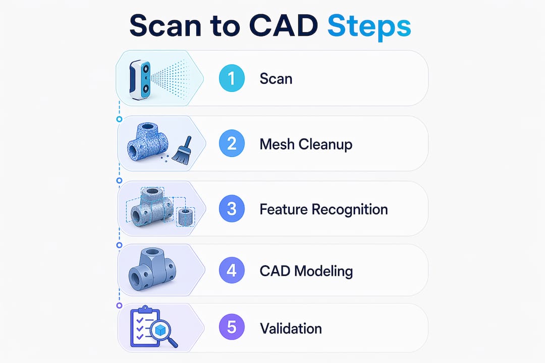
The scan-to-CAD process follows a five-step lifecycle: scanning, data export and import, alignment, feature extraction, and exporting parametric files. Each stage builds on the last, and skipping any one of them produces unreliable results downstream.

  1. Capture the object with a 3D scanner. Structured light scanners, laser scanners, and photogrammetry rigs all capture surface geometry as a point cloud. The output is a dense collection of XYZ coordinates that represents the physical object’s shape.

  2. Export the scan in a compatible file format. OBJ files carry color and texture, STL files carry geometry only, and STEP files carry parametric engineering data. Choosing the right format at this stage saves significant rework later. STL works for geometry checks; STEP is the target for fully editable engineering models.

  3. Import and align the mesh in CAD software. Once inside a tool like Autodesk Fusion 360 or Autodesk ReCap, the mesh must be oriented correctly. Misalignment in this step causes design errors that compound through every subsequent modeling decision.

  4. Extract features and reconstruct geometry. This is the most demanding step. You identify planes, cylinders, fillets, and other geometric primitives in the mesh, then model them as parametric features. Auto-surfacing the raw mesh almost always creates unmanageable files. Fitting primitives to the mesh produces clean, editable CAD geometry.

  5. Export the finished parametric model. The final output is a native CAD file, typically STEP or a format like SolidWorks SLDPRT, ready for modification, simulation, or direct manufacturing.

Pro Tip: A basic scan-to-CAD project can be completed in roughly 24 hours with the right hardware and software combination. Plan your scanning session carefully so you spend that time on modeling, not on fixing scan data.

Which tools are used for scan to CAD in 2026?

Designer editing 3D mesh in CAD software

The scan-to-CAD software and hardware market has matured significantly. The right combination depends on your accuracy requirements, budget, and the complexity of the part you are working with.

Professional-grade scanners:

  • Creaform HandySCAN and the Creaform Metrology Suite handle high-accuracy industrial scanning and include a dedicated Scan-to-CAD module that automates several post-processing steps.
  • Artec 3D scanners, including the Artec Eva and Artec Leo, are widely used for medium-complexity parts and organic shapes.

Mobile and accessible options:

  • iPhones and iPads equipped with LiDAR sensors (iPhone 12 Pro and later) provide a low-cost entry point for less demanding projects. Apps like Polycam export directly to formats compatible with Fusion 360.
  • AI-assisted tools reduce turnaround times by automating manual stages like point-cloud tracing, making mobile LiDAR a practical option for concept work and reference modeling.

CAD and post-processing software:

The trend in 2026 is toward AI-assisted mesh cleanup and feature recognition. These tools do not replace engineering judgment, but they cut the time spent on repetitive cleanup tasks by a meaningful margin. For complex organic shapes, Geomagic still leads. For prismatic mechanical parts, Fusion 360 with a clean STL import is often the fastest path.

What challenges do users face when converting scan data to CAD?

The biggest misconception in scan to CAD is treating the scan data as a finished model. A 3D scan is a visual reference blueprint. It shows you what the object looks like, not how it was designed. Getting an editable CAD model requires reconstruction, not conversion.

“A 3D scan is only a visual reference blueprint; manual reconstruction is needed to get an editable CAD model.” — Einstar Reverse Engineering Guide

Auto-surfacing raw scan meshes often leads to unmanageable files with thousands of irregular faces. The correct approach is to use the mesh as a dimensional reference and fit parametric features, like cylinders, planes, and fillets, on top of it. This takes more time but produces a model you can actually modify.

Mesh cleanup and alignment are the other major friction points. Dirty meshes with holes, noise, or overlapping faces cause feature extraction to fail or produce inaccurate geometry. Tools like Autodesk ReCap help orient and clean scans before they enter the CAD environment, but mesh cleanup and point cloud alignment still require operator attention and judgment.

Infographic detailing scan to CAD workflow steps

The post-scan processing phase consistently takes more time than the scanning itself. Experienced practitioners budget two to four times as much time for reconstruction as for data capture. If you are new to the CAD modeling workflow, that ratio is often surprising and worth planning for from the start.

Pro Tip: Not every scan needs to become a fully parametric solid model. For fit-check or reference work, using the scan mesh as an overlay inside Fusion 360 is faster and often sufficient. Match your modeling effort to the actual project goal.

How is scan to CAD applied in real prototyping and design workflows?

Scan to CAD has three primary applications in practical design and manufacturing work: reverse engineering broken or legacy parts, creating custom fixtures and enclosures, and accelerating product iteration.

Reverse engineering broken or legacy parts

When a part breaks and no drawing exists, a 3D scan gives you the geometry you need to recreate it. Editable scan-to-CAD files enable modifications like thickening ribs, adjusting tolerances, or changing materials before the part goes back into production. This is far faster than measuring by hand and rebuilding from scratch.

Custom fixture and enclosure design

Designers scan an existing assembly or environment, then model a new part directly around the scan data. A custom bracket, housing, or adapter can be designed to fit perfectly because the scan captures the actual geometry of the mating surfaces, not a nominal drawing that may not reflect real-world tolerances.

Accelerating product iteration with 3D printing

The combination of scan to CAD and 3D printing creates a tight iteration loop. You scan a physical prototype, modify the CAD model, print a revised version, and test it. Each cycle takes hours instead of days. This workflow is especially effective for ergonomic parts, consumer products, and any design where fit and feel matter as much as function.

Application Primary benefit Typical output format
Reverse engineering legacy parts Recreate geometry without original drawings STEP, SLDPRT
Custom fixture design Fit new parts to existing assemblies STEP, STL for printing
Product iteration with 3D printing Rapid physical testing of design changes STL for FDM or SLA printing
Digital asset creation Preserve physical objects as editable models OBJ, STEP

The 3D modeling process for businesses follows a similar logic: scan data provides the dimensional foundation, and CAD modeling adds the engineering intent. The two together produce results that neither can achieve alone.

Key takeaways

Scan to CAD converts physical objects into editable parametric models by combining accurate scan data with deliberate CAD reconstruction, and the quality of the output depends entirely on the operator’s modeling skill and process discipline.

Point Details
Scan data is a blueprint, not a model Raw scans require manual reconstruction to become editable CAD geometry.
Five-step workflow Scanning, export, alignment, feature extraction, and parametric export define every successful project.
Tool selection matters Geomagic Design X leads for organic shapes; Fusion 360 works well for prismatic mechanical parts.
Post-processing takes the most time Budget two to four times more time for reconstruction than for the scan itself.
Match effort to project goals Reference overlays in Fusion 360 can replace full solid modeling when fit-check is the only requirement.

Why scan to CAD is harder than it looks, and worth it anyway

I have seen a lot of people come into scan-to-CAD projects expecting the software to do the heavy lifting. They scan an object, import the mesh, hit a button, and expect a clean parametric model to appear. That is not how it works, and that gap between expectation and reality is where most projects stall.

The value of scan data is tied entirely to the operator’s ability to interpret and reconstruct design intent accurately. A mesh tells you where the surface is. It does not tell you whether that surface is supposed to be a 25mm cylinder or a 24.97mm cylinder with manufacturing variation. That judgment call is yours, and it requires both CAD skill and domain knowledge about the part you are modeling.

What I find genuinely exciting about the current state of the tools is that AI-assisted feature recognition in software like Geomagic Design X is starting to close that gap. It does not eliminate the need for engineering judgment, but it handles the tedious parts of mesh cleanup and primitive fitting faster than any manual workflow. For someone learning the process, that means you can focus your attention on the decisions that actually matter.

My honest recommendation: start with a simple prismatic part, something with flat faces, clear holes, and obvious geometry. Get that workflow clean before you attempt organic shapes or complex assemblies. The skills transfer directly, and you will build confidence in the process before the difficulty ramps up.

— Justin

Take your scan-to-CAD projects further with Cc3dlabs

If you are working on a project that requires precise scan data or professional CAD modeling support, Cc3dlabs offers professional handheld 3D scanning (accuracy to ~0.1 mm) and full CAD modeling services from its facility near Philadelphia. Whether you need a single part scanned and reconstructed or a full reverse engineering workflow for a production component, the team brings the equipment and expertise to deliver accurate, print-ready files.

https://cc3dlabs.com

From scan capture through to on-demand 3D printing of the finished model, Cc3dlabs handles the complete workflow. Local pickup is available, and shipping options cover clients across the United States and internationally. Request a free online estimate directly from the website to get started.

FAQ

What is scan to CAD in simple terms?

Scan to CAD is the process of taking a 3D scan of a physical object and converting that scan data into an editable CAD model. The result is a parametric file you can modify, manufacture, or 3D print.

What file formats are used in the scan-to-CAD process?

OBJ is preferred for color and texture, STL for geometry-only 3D printing, and STEP for parametric engineering models. STEP is the standard output format for fully editable scan-to-CAD results.

How long does a scan-to-CAD project take?

A basic project can be completed in roughly 24 hours with the right hardware and software. More complex parts with organic geometry or tight tolerances require significantly more time, primarily in the reconstruction phase.

Is scan to CAD the same as reverse engineering?

Scan to CAD is the primary method used in reverse engineering, but reverse engineering is the broader discipline. Reverse engineering can also involve manual measurement, teardown analysis, and functional testing beyond what scan data alone provides.

What is the hardest part of the scan-to-CAD workflow?

Feature extraction and parametric reconstruction are consistently the most demanding steps. Auto-surfacing raw meshes produces messy, uneditable geometry. Fitting geometric primitives manually to the mesh takes skill but delivers clean, usable CAD models.

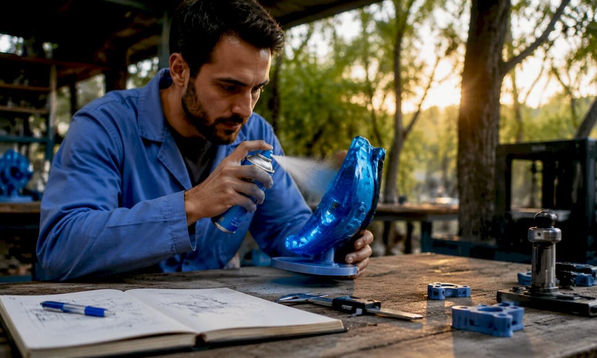
Technician applying matte spray on model

How to Prepare Models for Scanning: Pro Guide


TL;DR:

  • Proper 3D scan model preparation relies on surface control, stable positioning, and proper reference data to ensure a clean, accurate mesh. Applying matte coatings improves data quality on reflective or dark surfaces, while irregular marker placement and secure fixtures prevent tracking errors and model shifts. Effective post-scan processing includes cleaning, decimating, and retopologizing meshes, with appropriate file formats chosen based on the intended use.

Proper 3D scanning model preparation is the single biggest factor separating a clean, usable mesh from a session full of noise and gaps. Knowing how to prepare models for scanning means controlling three variables before the scanner ever fires: surface condition, physical stability, and reference data. Skip any one of them and you will spend more time fixing the mesh than you saved by rushing setup. This guide covers surface treatment with sprays like AESUB Blue, positioning with turntables and adhesive markers, post-scan processing in tools like Blender and MeshLab, and the troubleshooting moves that save a scan session when things go sideways.

How to prepare models for scanning: surface and material basics

The surface your scanner sees determines the quality of the data it captures. Shiny, reflective, transparent, and very dark surfaces all cause the same core problem: the scanner cannot resolve a consistent return signal, so it either skips those areas entirely or fills them with noise.

The surfaces that cause the most trouble are:

  • Highly polished metals (chrome, brushed aluminum, mirror steel)
  • Clear or translucent plastics (acrylic, polycarbonate, glass)
  • Jet-black or very dark matte surfaces (absorb structured light)
  • Organic materials with subsurface scatter (skin, wax, rubber)

The fix for nearly all of these is a temporary matte coating. Professional scanning sprays like AESUB Blue deposit a micron-thin powder layer that gives the scanner a uniform, diffuse surface to read. AESUB Blue is self-sublimating, meaning it evaporates within a few hours without leaving residue. Dry shampoo is a widely used field substitute when a dedicated spray is unavailable. Both work by breaking up specular reflection.

Apply the spray in short, even passes from about 30 centimeters away. The goal is a uniform frost, not a thick coat. Thick coats add measurable material to the surface and obscure fine detail like text, threads, and sharp edges.

Pro Tip: Test your spray on a scrap piece of the same material before coating the actual model. Some plastics react with aerosol propellants and develop a haze that does not sublimate cleanly.

Infographic with step-by-step scanning preparation

Matte gray and light tan surfaces scan without any coating in most cases. If you are working with a high quality scan for manufacturing, confirm the surface finish requirement before applying anything that could alter dimensional accuracy.

How to position and secure models for accurate scanning

Model movement during a scan is the fastest way to destroy data quality. Even a fraction of a millimeter of shift between passes creates misaligned point clouds that no software can fully correct in post-processing.

Follow these steps to lock down your setup before scanning begins:

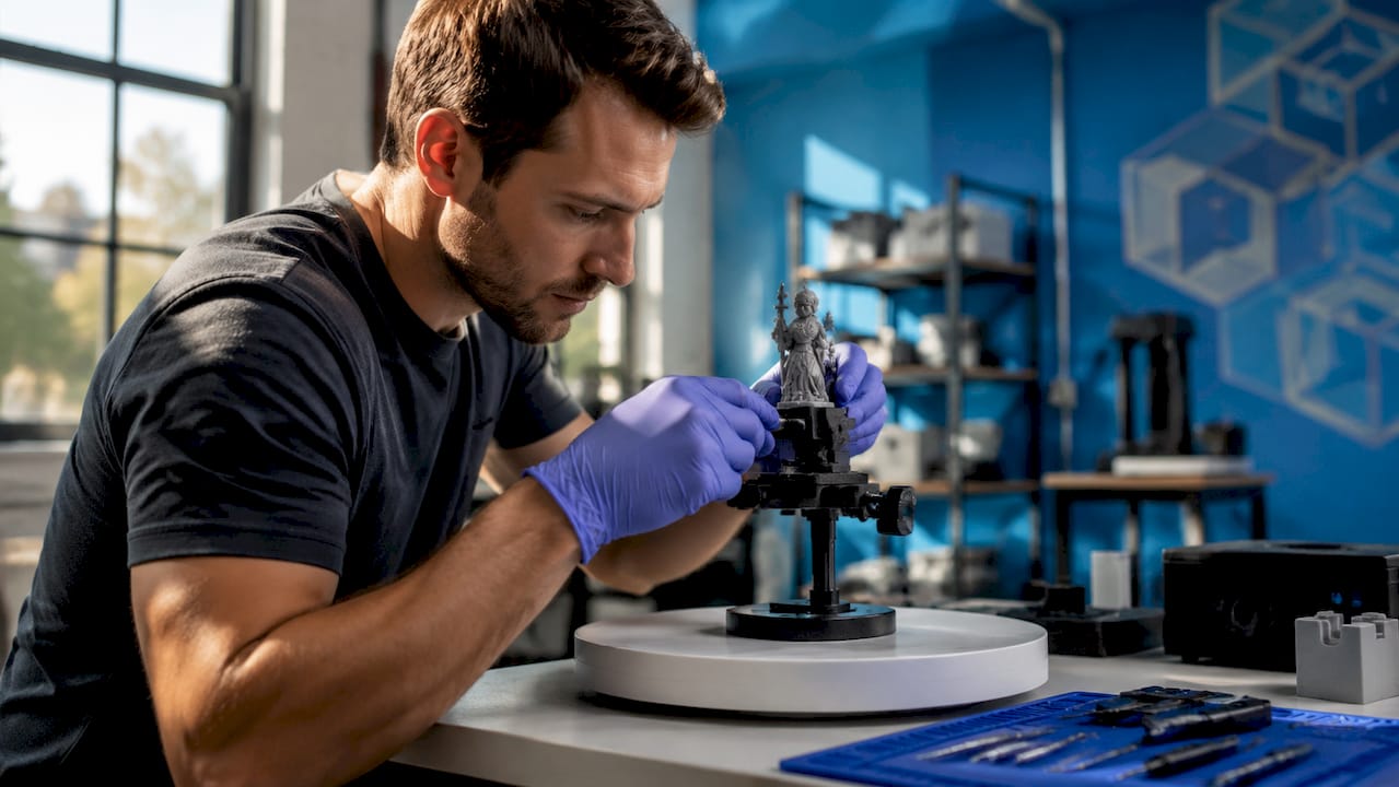
  1. Place the model on a turntable. Motorized turntables let you rotate the object consistently while keeping the scanner stationary. This produces more uniform coverage than moving the scanner around a fixed object.
  2. Use fixtures or clamps for irregular shapes. Flexible arms and foam cradles hold odd geometries without deforming them. Turntables and fixtures prevent the movement that reduces scan accuracy most.
  3. Apply adhesive reference markers before scanning. Place them on flat or featureless areas where the scanner has little natural geometry to track. At least 5 markers must be visible in the scanner’s field of view at all times to maintain positional accuracy.
  4. Distribute markers irregularly. Symmetric or evenly spaced markers confuse the scanner’s feature-tracking algorithm. Irregular marker placement is what enables reliable tracking across featureless geometry.
  5. Plan for deep holes and grooves separately. These areas require dedicated scan passes at oblique angles. Do not expect a single turntable rotation to capture internal geometry.

Pro Tip: Flexible clamps are useful for holding thin or delicate parts, but tighten them only until the part stops moving. Overtightening deforms flexible materials and introduces dimensional error that shows up in the final mesh.

For complex assemblies, consider scanning sub-components separately and merging the point clouds in software. This approach gives you better coverage of internal features and reduces the total number of scan passes needed per session.

Hands securing model with clamp for scanning

Which tools and accessories improve scanning efficiency?

The right accessories reduce setup time and improve first-pass data quality. Here is a comparison of the core tool categories and what to look for in each:

Tool Category Budget Option Professional Option Key Consideration
Scanning spray Dry shampoo AESUB Blue Self-sublimating sprays preserve dimensions
Turntable Manual photography turntable Motorized scanning turntable Motorized units produce consistent rotation speed
Lighting Daylight LED panels Controlled LED ring lights Even lighting without shadows reduces geometric artifacts
Reference markers Generic dot stickers Coded photogrammetry targets Coded targets give software absolute position data
Scanner mount Tripod Articulating arm Arms allow faster repositioning for complex geometry

Lighting deserves more attention than most guides give it. Harsh directional light creates shadows that the scanner reads as geometry. The result is false surface detail baked into your mesh. Use two or more diffuse LED panels positioned at 45-degree angles to the object. This eliminates most shadow artifacts without washing out surface texture.

For photogrammetry workflows specifically, camera settings matter as much as lighting. Shoot at ISO 100–400, use a small aperture (f/8–f/11) for depth of field, and keep shutter speed fast enough to avoid motion blur. Consistent exposure across all frames is what allows photogrammetry software like RealityCapture or Metashape to align images accurately.

What are the key steps in post-scan mesh processing?

Raw scan data is not a finished model. Raw scan meshes can contain several million polygons, which is far more than any downstream workflow needs and too heavy for most software to handle efficiently.

Here is the standard processing sequence:

  1. Clean the raw mesh. Remove floating points, isolated clusters, and obvious scan artifacts. Tools like MeshLab and Blender’s Clean Up functions handle this well for most scan types.
  2. Fill holes selectively. Small holes from marker removal or occluded geometry can be filled. Avoid aggressive hole-filling on scan data destined for CAD. Aggressive smoothing or hole-filling reduces physical accuracy in CAD workflows.
  3. Decimate the mesh. Decimation targets 5–10% of the original polygon count before retopology. A 10-million-polygon raw scan becomes a 500,000 to 1,000,000-polygon working mesh.
  4. Retopologize for your use case. Production models for animation need quad-dominant meshes with proper edge loops. Retopology should combine automated tools and manual refinement for production-ready results. Blender’s Shrinkwrap modifier is a reliable starting point for manual retopology over a decimated base.
  5. Export in the correct format. OBJ and STL work for most 3D printing workflows. STEP or IGES is required for CAD integration. Aligning scan data within CAD software using planes and cross-sections produces the most accurate sketches for modeling.
Processing Stage Recommended Tool Output
Mesh cleanup MeshLab, Blender Clean, artifact-free mesh
Decimation MeshLab, ZBrush Reduced polygon mesh
Retopology Blender, Wrap3 Quad-dominant production mesh
CAD alignment SolidWorks, Fusion 360 Dimensionally accurate CAD model

Before you retopologize, analyze the asset’s intended use to set the right polygon budget. A real-time game asset needs a fraction of the polygons that a film-quality render requires. Getting this decision right before retopology saves hours of rework.

What common challenges arise during scanning preparation?

Even well-prepared scans run into problems. Knowing what to look for before you start saves significant time in post-processing.

The most frequent issues and their fixes:

  • Reflective surfaces still causing noise after spraying. Apply a second thin coat and wait 60 seconds before scanning. If noise persists, the surface may need a different spray chemistry or a physical matte film.
  • Markers not being tracked reliably. Check spacing and pattern. Markers placed in a grid or at equal intervals reduce tracking robustness. Redistribute them in a random, asymmetric pattern.
  • Model shifting mid-scan. Stop the session immediately. Reposition and re-secure the model, then restart. Attempting to merge a shifted scan in software produces unreliable results.
  • Incomplete coverage on complex geometry. Plan additional scan passes at oblique angles before the main session. Undercuts, deep channels, and internal cavities almost always need dedicated capture angles.
  • Noisy or spiky mesh output. This usually points to inadequate lighting or surface coating. Review your lighting setup and check for reflections from nearby surfaces, walls, or equipment.

The most overlooked step in scanning preparation is a dry run. Scan a simple test object with the same surface treatment and lighting before committing to the actual model. This catches lighting and coating problems in minutes rather than hours.

Iterative testing is the professional standard, not a sign of inexperience. Aerospace and precision manufacturing workflows, for example, routinely include test scans of reference geometry before scanning the actual part. This practice validates the entire setup, from lighting to marker placement to scanner calibration, before the critical scan begins.

Key takeaways

Effective 3D scanning model preparation requires surface treatment, stable positioning, and disciplined post-scan processing to produce accurate, usable mesh data.

Point Details
Surface coating is non-negotiable Apply matte sprays like AESUB Blue to reflective, transparent, or dark surfaces before scanning.
Marker placement must be irregular Place at least 5 reference markers in an asymmetric pattern to maintain scanner tracking accuracy.
Secure the model completely Use turntables and fixtures to eliminate movement that corrupts point cloud alignment.
Decimate before retopology Reduce raw meshes to 5–10% of original polygon count before rebuilding topology for production use.
Preserve raw data for CAD Avoid aggressive smoothing or hole-filling on scan data going into CAD workflows to protect dimensional accuracy.

What i have learned preparing models for professional scans

The part of scanning preparation that most guides undervalue is patience at the setup stage. Every minute spent checking marker placement, coating uniformity, and lighting angles saves at least ten minutes of mesh repair. That ratio holds whether you are scanning a small figurine or a full automotive component.

The other thing I have found consistently true: the tools matter less than the process. I have seen clean, usable scans produced with a budget turntable and dry shampoo, and I have seen expensive scanner sessions produce unusable data because nobody checked the lighting. The scan accuracy optimization process is repeatable and learnable. The technology is not magic.

AI-assisted retopology tools are genuinely changing the post-processing side of this work. What used to take a skilled artist several hours of manual retopology can now be roughed out in minutes with tools like Tripo3D’s AI retopology, then refined by hand. The human judgment still matters for edge loops around joints and deformation areas, but the grunt work is increasingly automated.

My honest advice: build a preparation checklist specific to your scanner and your most common object types. Laminate it. Use it every session. The professionals who produce the most consistent scan data are not the ones with the best equipment. They are the ones with the most disciplined setup habits.

— Justin

Get professional scanning results with Cc3dlabs

Preparation expertise only goes so far when the geometry is complex or the tolerances are tight. Cc3dlabs operates a full 3D scanning lab near Philadelphia, handling professional handheld 3D scanning (accuracy to ~0.1 mm), surface preparation, and complete post-scan processing for prototypes, functional parts, and production components.

https://cc3dlabs.com

Whether you need a single part scanned and converted to a CAD-ready model or a batch of components processed for manufacturing, Cc3dlabs manages the full workflow from physical model to finished file. The team also provides 3D printing services to take your scan data directly into production. Request a free estimate online or arrange local pickup to get started.

FAQ

What surfaces are hardest to scan accurately?

Highly reflective metals, clear plastics, and jet-black surfaces cause the most scanning problems because they scatter or absorb the scanner’s light source. Apply a temporary matte coating like AESUB Blue to resolve most surface-related scan failures.

How many reference markers do i need for a scan session?

At least 5 adhesive reference markers must be visible in the scanner’s field of view at all times. Place them in an irregular, asymmetric pattern so the scanner’s tracking algorithm can distinguish individual markers reliably.

What is the right polygon count after decimation?

Target 5–10% of the raw scan’s original polygon count as your working mesh before retopology. The final polygon budget depends on the intended use: real-time assets need far fewer polygons than film or archival models.

Should i fill holes in my scan mesh before importing to CAD?

Avoid aggressive hole-filling on scan data going into CAD workflows. Filling holes can alter surface geometry and reduce dimensional accuracy. Keep the mesh non-watertight and handle geometry reconstruction inside the CAD environment instead.

What file format should i export for 3d printing versus CAD?

Export STL or OBJ for 3D printing workflows. Use STEP or IGES when the scan data needs to integrate with CAD software like SolidWorks or Fusion 360 for precise modeling and assembly work.