
TL;DR:
- Achieving precise and consistent 3D scan data requires thorough object preparation, appropriate scanner selection, and deliberate environmental control. Techniques like multi-angle scanning, slow overlapping passes, and real-time coverage checks significantly improve accuracy. Post-processing, including careful alignment, noise removal, and validation against references, is essential for producing reliable models.
Getting consistent, precise data from a 3D scanner is harder than the product demos make it look. Whether you’re capturing a machined part for reverse engineering, scanning an organic form for product development, or working up a prototype at home, knowing how to optimize 3D scan accuracy separates usable data from a frustrating rebuild. Incomplete geometry, surface noise, and misaligned point clouds are not hardware problems — they’re technique problems. This guide covers every phase from object prep through post-processing so you can get it right the first time.
Table of Contents
- Key Takeaways
- How to optimize 3D scan accuracy before you start
- Step-by-step scanning techniques for better precision
- Post-processing best practices for accurate models
- Common mistakes that compromise scan accuracy
- Verification methods that confirm scan accuracy
- My honest take on mastering 3D scan accuracy
- Get professional-grade 3D scanning and printing with Cc3dlabs
- FAQ
Key Takeaways
| Point | Details |
|---|---|
| Prepare surfaces before scanning | Apply matte spray to reflective or dark objects to significantly improve point cloud quality. |
| Multi-angle scanning closes data gaps | Scanning horizontally and vertically captures crevices and undercuts a single pass will miss. |
| Slow, overlapping movement is non-negotiable | Erratic scanner movement causes tracking loss and leaves data holes that are hard to repair later. |
| Post-processing must be methodical | Align, then clean noise, then fill holes in that order to avoid compounding errors in your mesh. |
| Verify accuracy against a reference | Compare your scan output against physical measurements or a CAD model before committing to production. |
How to optimize 3D scan accuracy before you start
Most accuracy problems are baked in before the scanner ever powers on. Preparation is where you make or break the final result, and it deserves more attention than most guides give it.
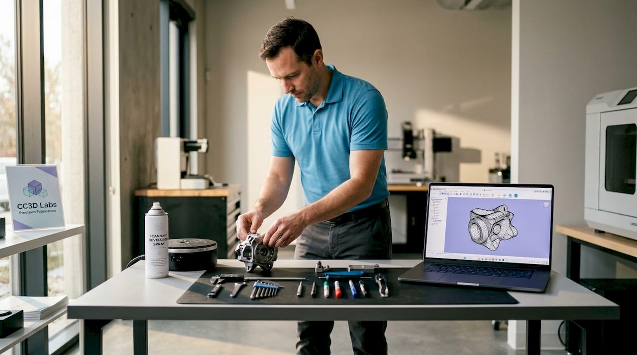
Surface treatment comes first. Objects with reflective, transparent, or very dark surfaces frequently require matte spray to improve scan fidelity. Structured light and photogrammetry-based scanners rely on reading surface texture and light patterns. A polished aluminum bracket or a black rubber gasket gives the sensor almost nothing to work with, producing sparse, noisy point clouds. A quick coat of removable scanning spray gives those surfaces the diffuse reflectivity they need.
Match your scanner to the object. A long-range LiDAR unit designed for architectural capture will not resolve the fine features of a 30mm mechanical component. Conversely, a close-range structured light scanner with a small field of view will lose tracking on a large enclosure. Before you scan, confirm your scanner’s rated accuracy, resolution, and working distance are appropriate for the object’s size and the level of detail you need to capture.
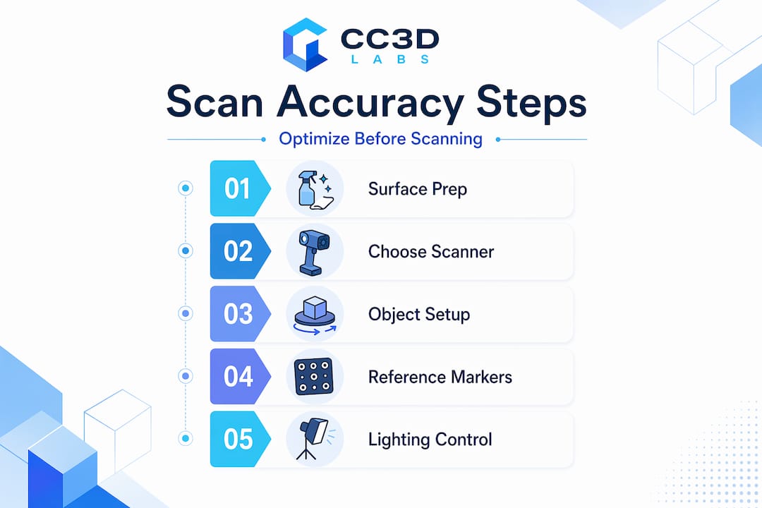
Control your environment deliberately. Harsh shadows and direct sunlight cause errors and reduce model fidelity in ways that post-processing cannot fully recover. Set up in a space with soft, diffuse lighting. Overcast daylight works well outdoors. Indoors, use diffused studio lights or even translucent panels over standard fixtures. Avoid scanning near windows with strong directional sun.
Here’s a pre-scan checklist worth running through every time:
- Clean the object of dust, grease, and fingerprints
- Apply scanning spray to reflective, transparent, or very dark areas
- Stabilize the object on a turntable or non-slip mat so it cannot shift mid-scan
- Confirm ambient lighting is soft and consistent from all angles
- Check that the scanner is fully warmed up and recently calibrated
Pro Tip: Place your object on a lazy Susan turntable with reference markers printed on the mat underneath. The scanner tracks the markers while you rotate the object, giving you automatic alignment across passes without any repositioning guesswork.
Step-by-step scanning techniques for better precision
With prep complete, what you do during the scan determines how much cleanup you create for yourself afterward. These techniques directly support improving 3D scanning precision.
-
Move slowly and use overlapping passes. Slow, steady movement with overlapping passes prevents tracking loss and gaps in data. A general rule: each new pass should share at least 30% overlap with the previous one. Think of it like mowing a lawn rather than driving across a field.
-
Alternate between horizontal and vertical scanner orientations. Rotating the scanner vertically reveals hidden crevices and undercuts that horizontal scanning misses entirely. This is one of the most underused techniques for capturing complex objects. Run a full horizontal pass, then tilt the scanner 90 degrees and make a dedicated vertical pass over any concave areas, threads, or slots.
-
Apply markers to challenging or symmetrical surfaces. Markers improve scan stability and reduce tracking loss for objects with uniform color, repetitive geometry, or large featureless flat sections. Stick retro-reflective targets in irregular patterns across the object’s surface. The scanner uses these as fixed reference points when natural texture is insufficient.
-
Adjust exposure and resolution settings for each object. A shiny metallic surface needs lower exposure than a matte plastic part to avoid overblown returns. Reduce resolution slightly on large, simple forms to keep file sizes manageable. Max out resolution only when fine surface detail genuinely matters for your downstream workflow.
-
Scan from multiple orientations to ensure full coverage. Combining scans from different positions produces more complete coverage of hard-to-reach areas. For most freeform objects, plan for at least three to five distinct scan positions: top, front, back, and both sides at minimum.
-
Monitor tracking feedback in real time. Most scanning software shows a live tracking indicator. If it starts to drop, stop and back up slightly rather than pushing forward. Recovering lost tracking mid-scan is almost always cleaner than trying to repair the resulting gap in post.
Pro Tip: For symmetrical objects like cylindrical parts or spherical housings, break the symmetry artificially by taping a small piece of masking tape in an irregular position. This gives the scanner a unique reference point to track across the full rotation.
Post-processing best practices for accurate models
Raw scan data is never the finished product. The post-processing phase is where you turn a rough point cloud into a dimensionally accurate mesh, and how you approach it matters as much as the scan itself.
Align before you clean. When working with multiple scan passes, register and align all scans first before touching noise removal or mesh operations. Trying to merge passes after you’ve already modified one of them creates mismatches that can be nearly impossible to reconcile.
Post-processing steps like noise removal, mesh alignment, and hole filling are critical to preserving model accuracy. The order matters:
- Alignment and registration. Use your software’s global registration function after doing a rough initial alignment. Software with advanced point cloud registration can significantly improve results, particularly when scans have limited overlap. Displacement-corrected geometric consistency algorithms are now making their way into commercial tools and dramatically improve reliability in low-overlap conditions.
- Noise and outlier removal. Use statistical outlier filters with conservative settings. Aggressive noise removal destroys fine surface detail. Run the filter once at low strength, then visually inspect before applying again.
- Hole filling and mesh repair. Fill small holes automatically, but handle large holes manually. Automated tools will often interpolate surface curvature incorrectly across wide gaps, creating geometry that was never actually scanned.
- Export format selection. Export in formats appropriate to your workflow. OBJ and STL are standard for 3D printing and CAD import. PLY retains color and per-point metadata if you need it for inspection or archival. STEP or IGES are better for direct CAD environments when your software supports scan-to-CAD conversion.
Pro Tip: Before you export, run a quick visual inspection by cross-sectioning the mesh in your software. Slicing through the model at several planes reveals internal voids, duplicate geometry, and inverted normals that won’t be obvious from the outside.
Common mistakes that compromise scan accuracy
Even experienced operators repeat these errors. Knowing what to watch for saves you a full rescan.
-
Ignoring environmental factors. Environmental vibrations, temperature swings, or air movement degrade scan quality by introducing noise and tracking errors. A large HVAC unit cycling on and off near your scan table is enough to introduce measurable error over a long scan session. Scan in a stable, quiet environment whenever precision is critical.
-
Scanning too fast. Speed feels productive but erratic or rapid movements cause incomplete or misaligned scan passes. The scanner needs time to process and register each frame. Double the time you think you need for any object with complex geometry.
-
Skipping regular calibration. Skipping calibration leads to inaccurate dimensions and misaligned scans, especially in engineering applications where tolerances are tight. Calibrate at the start of each session, after transport, and any time the scanner has been exposed to significant temperature change.
-
Not checking coverage in real time. On-site quality checks during scanning reduce rework and improve model completeness. Discovering a missing area when you’re back at your desk means setting up the whole scan again. Spend 30 seconds reviewing coverage before you move the object.
“The single most expensive mistake in 3D scanning is assuming you got it. Verify before you move anything.” This is worth repeating every time you scan a critical part.
Verification methods that confirm scan accuracy
Producing a mesh is not the same as producing an accurate mesh. These techniques help you know which one you have.
| Verification method | What it checks | When to use it |
|---|---|---|
| Physical measurement comparison | Key dimensions against calipers or CMM data | Before any manufacturing commitment |
| CAD overlay deviation map | Color-coded deviation between scan and CAD | Reverse engineering and inspection workflows |
| Point cloud overlap analysis | Percentage of coverage and alignment error | After merging multiple scan passes |
| Reference target residuals | Error values from marker-based alignment | Whenever markers are used during scanning |
For high-stakes applications, compare your scan against a physical measurement reference at multiple checkpoints, not just the overall bounding dimensions. A scan can look dimensionally correct at the extremes while carrying localized errors in complex features. CAD overlay tools in software like Geomagic or Polyworks generate heat maps that visualize exactly where deviation is occurring and by how much.
Advanced algorithms like displacement-corrected geometric consistency significantly improve point cloud registration accuracy, particularly in low-overlap conditions. If your scanning software has registration quality scoring, pay attention to it. A high alignment error at the merge stage means your final model carries that error everywhere downstream.
Pro Tip: Scan a known reference object, such as a calibrated sphere or gauge block, at the start of each session. Measure it in software and compare to its certified dimensions. This gives you a real-world accuracy baseline for that specific scan session, not just the manufacturer’s spec sheet.
My honest take on mastering 3D scan accuracy
In my experience, the biggest gap between mediocre scans and exceptional ones is not hardware. I’ve watched engineers with top-tier scanners produce unusable data because they were in a hurry, and I’ve seen hobbyists with mid-range units capture engineering-grade geometry because they were patient and methodical.
Real-time verification changed how I work. I used to finish a full scan session and find missing coverage back at the workstation. Now I treat verification as part of the scanning workflow, not a step after it. That single habit cut my rescan rate dramatically.
The other thing I’ve learned: multi-angle scanning is not optional on anything with undercuts, threads, or deep pockets. A single-pass horizontal scan of a threaded housing looks complete until you try to use the mesh and realize all the thread geometry is missing. Adding a dedicated vertical pass takes five extra minutes and saves an hour of repair work.
The myth I push back on hardest is that a better scanner solves accuracy problems. It doesn’t. Technique, environment, and patience solve accuracy problems. The scanner is just the measurement tool. How you use it determines everything.
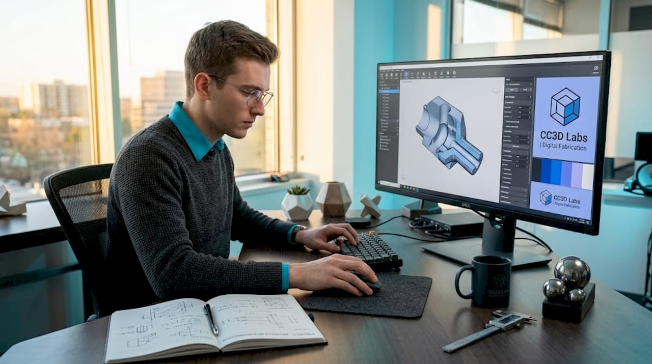
Get professional-grade 3D scanning and printing with Cc3dlabs

If you’re working on a project where accuracy genuinely matters, whether it’s a functional prototype, a reverse-engineered component, or a production part series, the DIY path has real limits. Cc3dlabs offers metrology-grade scanning services alongside full-cycle 3D printing for engineers and product developers who need results they can trust. The team near Philadelphia handles everything from scan capture through final print, so your data quality is validated at every step. You can also explore the scanning accuracy checklist on the site to cross-reference your current workflow against professional standards. Get a free estimate online or reach out directly if you have a complex part that’s been giving you trouble.
FAQ
What causes poor accuracy in 3D scans?
Poor accuracy most often comes from environmental issues, surface conditions, and scanning technique rather than hardware. Reflective surfaces, harsh lighting, rapid scanner movement, and skipped calibration are the leading causes.
How many scan passes do I need for a complete model?
Most objects require at least three to five distinct scan orientations to achieve full coverage. Complex parts with undercuts, crevices, or internal features need more, and a dedicated vertical-orientation pass is often required.
Do I need scanning spray for every object?
Not every object needs it, but any surface that is highly reflective, transparent, or very dark should be treated. These surface types cause sparse or noisy point clouds that are difficult to repair in post-processing.
How often should I calibrate my 3D scanner?
Calibrate at the start of every scan session, after transporting the scanner, and after any significant temperature change. Skipping calibration introduces dimensional drift that accumulates across a session.
What file format should I export for engineering use?
OBJ and STL work well for most 3D printing applications. For CAD integration and inspection workflows, STEP or IGES formats preserve geometric data more reliably when your software supports scan-to-CAD conversion.