

TL;DR:
- The STL file format describes 3D surface geometry as a mesh of triangles, mainly used for 3D printing. It stores only geometric data, with binary format being the most common for faster processing. Proper mesh integrity and verified scale are crucial for successful printing, as the format lacks unit or material information.
The STL file format is defined as a method for representing 3D surface geometry as a tessellated mesh of triangles, and it serves as the primary exchange format between 3D modeling software and 3D printers worldwide. STL stands for Stereolithography, a name inherited from the printing technology it was created to support. The format stores only geometric data: no color, no texture, no material properties, and no unit specification. Understanding what is STL file format means understanding its strengths and its hard limits, both of which directly affect whether your print succeeds or fails.
What is the STL file format and how does it work?
The STL format was developed by 3D Systems in 1987 to support the first commercial stereolithography 3D printers. That origin explains both its design and its limitations. The format was built for one job: describing the outer surface of a 3D object so a machine could build it layer by layer.
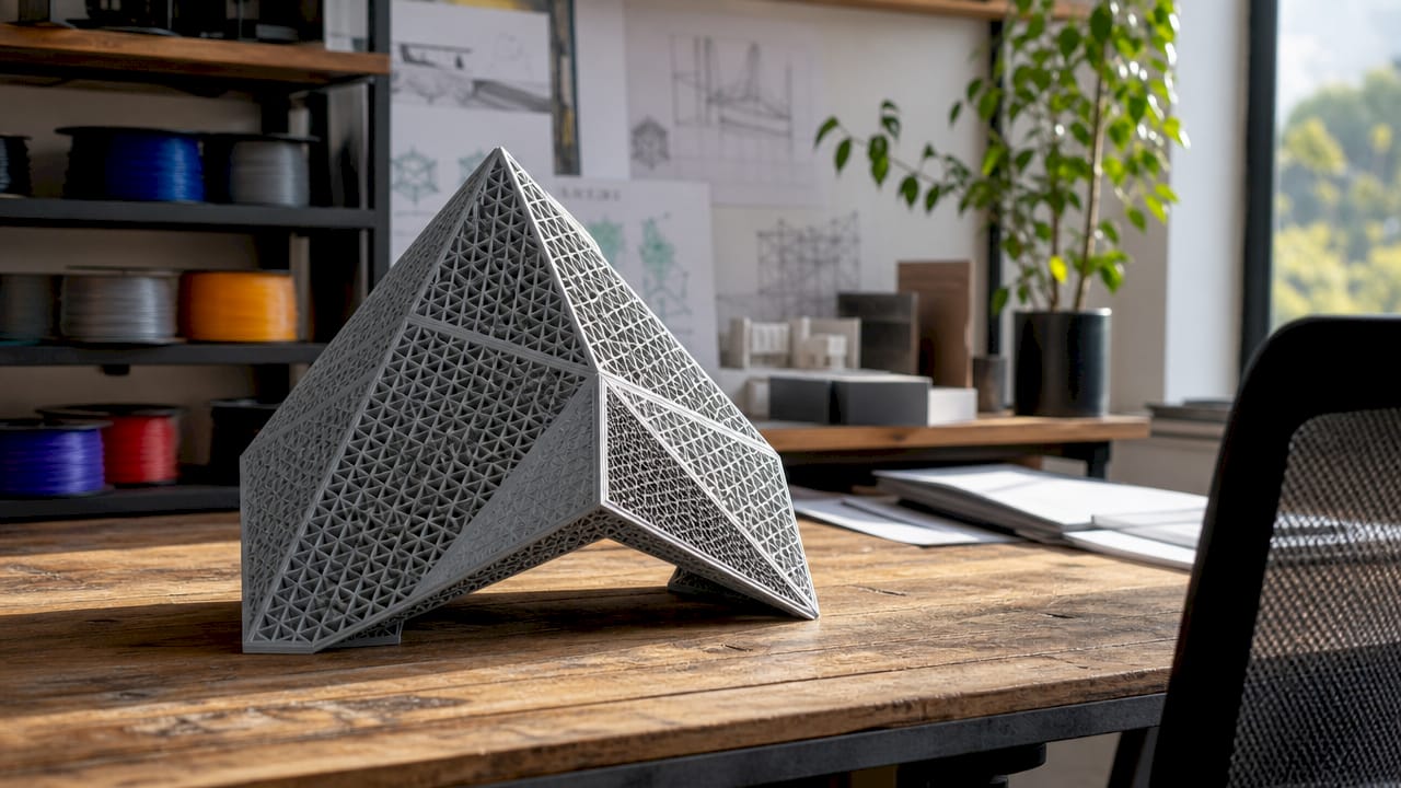
Every STL file encodes a 3D model as a collection of triangular facets. Each triangle is defined by three vertices and one outward-pointing normal vector. The normal vector tells the software which side of the triangle faces outward, which matters for determining the inside and outside of a solid object. Thousands or millions of these triangles combine to approximate any curved or complex surface.
ASCII vs. binary: two ways to store the same data
STL files come in two formats: ASCII and binary. ASCII STL writes every coordinate as human-readable text, which makes it easy to inspect but produces very large files. Binary STL stores the same data as raw numbers. Binary STL files are roughly 5 to 10 times smaller than their ASCII equivalents and load significantly faster. That size and speed advantage explains why approximately 95% of STL files in active use are binary.
The binary structure follows a fixed layout. Each file begins with an 80-byte header, followed by a 4-byte integer that records the total triangle count. After that, each triangle facet uses exactly 50 bytes: 12 bytes for the normal vector, 36 bytes for the three vertices, and 2 bytes for an attribute field that most software ignores. This deterministic layout is why binary STL loads so fast. Software can calculate exactly where each triangle starts without scanning the entire file.
| Property | ASCII STL | Binary STL |
|---|---|---|
| File size | Large (text-based) | 5–10x smaller |
| Human readable | Yes | No |
| Load speed | Slow | Fast |
| Industry usage | Rare | ~95% of files |
| Header structure | Text keywords | 80-byte fixed header |
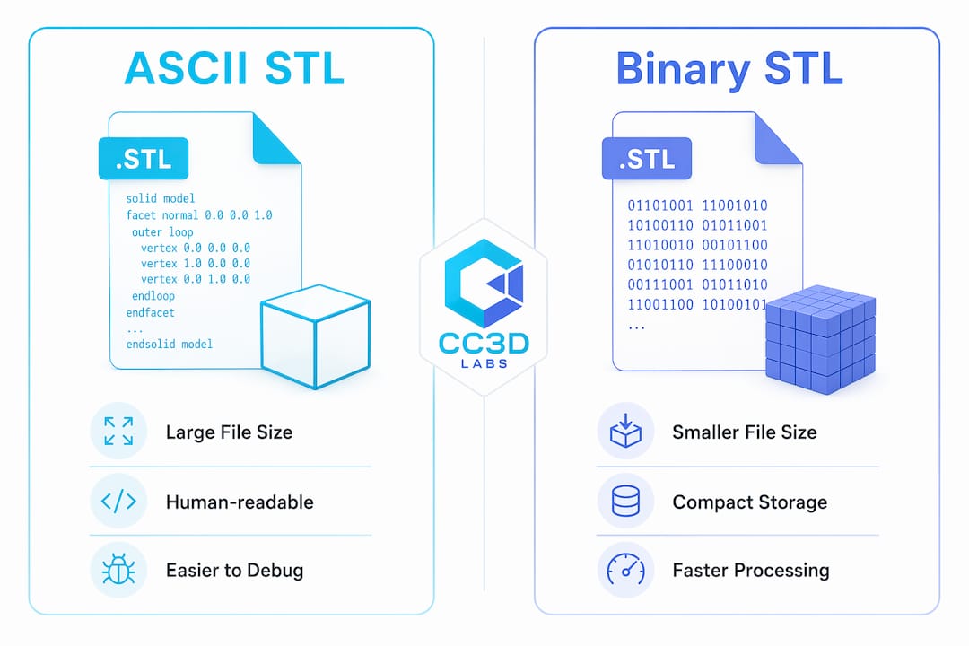
Pro Tip: When exporting from CAD software, always choose binary STL unless you specifically need to inspect the raw file data. Binary files transfer faster, load faster in slicers, and cause fewer memory issues with high-polygon models.
How do STL files interact with 3D printers?
STL files do not control 3D printers directly. A printer cannot read an STL file and start printing. Instead, slicing software converts the geometry into machine-specific instructions called G-code, which tells the printer’s motors and extruder exactly where to move and when to deposit material. The STL file is the input; G-code is the output.
This two-step process has a major practical consequence. The STL file carries no print settings. Layer height, infill density, support structures, print speed, and material type are all decided inside the slicer, not stored in the STL. Two people can take the same STL file and produce completely different physical parts depending on their slicer settings.
The format’s compatibility is its greatest strength. Nearly every 3D printer on the market, from desktop FDM machines to industrial SLA systems, accepts STL files. Nearly every slicer program reads them without conversion. That universal support is why STL remains the default format for sharing and submitting 3D models, even as newer formats have emerged.
The 3MF format, created in 2015 by a consortium that included 3D Systems, addresses many of STL’s gaps. 3MF files can store color, material assignments, print settings, and multi-part assemblies in a single file. For multi-color or multi-material prints, 3MF is the better choice. For standard single-material prints, STL’s simplicity and universal compatibility still make it the practical default.
- STL files store geometry only. No color, texture, material, or print settings travel with the file.
- Slicing software reads the STL and generates G-code for the specific printer.
- STL is compatible with virtually all consumer and professional 3D printers.
- 3MF supports richer data but requires software that can read and write the format.
- OBJ files carry UV maps and color data, making them better suited for visual rendering than for printing.
- For CAD file format selection, the right choice depends on whether you need geometry only or full manufacturing data.
What are the most common STL file problems?
The single most disruptive property of STL files is that they are unitless. The format records coordinates as numbers with no attached unit. A value of “25” could mean 25 millimeters, 25 inches, or 25 centimeters. A common scaling error produces prints that are 25.4 times too large or too small because the slicer assumed millimeters while the CAD software exported in inches. Always verify the model’s dimensions inside your slicer before sending a job to print.
The second major problem is mesh integrity. A printable STL file must be “watertight,” meaning the mesh has no holes, no overlapping faces, and no inverted normals. Non-manifold geometry causes slicers to fail or produce incorrect toolpaths, which leads to print failures. A mesh with a single missing triangle can make an entire model unprintable.
Mesh errors are common because they are easy to create and hard to spot visually. A model can look perfect on screen while containing dozens of internal errors that only appear when the slicer tries to process it.
- Check scale first. Open the STL in your slicer and confirm the dimensions match your design intent before adjusting any other settings.
- Run a mesh validation. Use mesh repair tools available in most professional slicers or dedicated programs to identify holes, inverted normals, and non-manifold edges.
- Fix errors before slicing. Repair tools can close holes and correct normals automatically, but review the result to confirm the geometry still matches your design.
- Re-export cleanly from CAD. If errors are extensive, the most reliable fix is correcting the source model and re-exporting rather than patching the STL.
- Validate again after repair. Run a second check after any repair to confirm no new errors were introduced during the fix.
Pro Tip: Mesh validation is not optional for production parts. A model that prints successfully once can fail on the next run if the slicer interprets ambiguous geometry differently. Validate every file before every production batch. For a structured approach, the 3D design validation guide at Cc3dlabs covers this in detail.
STL vs. OBJ and 3MF: which format should you use?
STL’s simplicity is both its strength and its constraint. The format does one thing well: it describes surface geometry. That focus makes it universally readable but limits what information travels with the file. Understanding when to use STL versus alternative formats saves time and prevents avoidable errors.
OBJ is the most common alternative for visual work. OBJ files support UV texture maps, vertex colors, and material libraries, which makes them the standard for game assets, film rendering, and visual design. For 3D printing, OBJ’s extra data is largely irrelevant unless the printer supports full-color output. Most FDM printers ignore color data entirely.
3MF is the format most likely to replace STL for manufacturing workflows over the next decade. It stores geometry, color, materials, print settings, and multi-part assemblies in a single compressed file. 3MF was created in 2015 specifically to address the gaps that STL left open. The format is gaining adoption in professional environments, particularly for multi-material and multi-color printing.
| Format | Color/Texture | Print settings | Multi-part | Best use case |
|---|---|---|---|---|
| STL | No | No | No | Single-material printing, universal sharing |
| OBJ | Yes | No | No | Visual rendering, color models |
| 3MF | Yes | Yes | Yes | Multi-material, full manufacturing data |
STL remains the backbone of single-material 3D printing because its simplicity guarantees compatibility. No slicer or printer rejects an STL file. That guarantee matters in production environments where reliability outweighs features. For printable templates and ready-to-print geometry, resources like CacheWerk’s 3D print files demonstrate how STL’s universal format makes sharing models across platforms frictionless.
Key Takeaways
The STL file format remains the most universally supported method for sharing 3D geometry for printing, but its lack of units, color, and material data makes mesh quality and slicer settings the true determinants of print success.
| Point | Details |
|---|---|
| STL stores geometry only | No color, texture, material, or unit data travels with the file. |
| Binary format dominates | ~95% of STL files are binary, which is 5–10x smaller than ASCII. |
| Slicers bridge the gap | Slicing software converts STL geometry into printer-specific G-code. |
| Unitless files cause errors | Always verify model dimensions in your slicer to avoid 25.4x scaling mistakes. |
| Mesh integrity is critical | A watertight, manifold mesh is required for a successful print. |
Why STL’s simplicity is still its superpower
After working with 3D files across dozens of production runs, I’ve come to a conclusion that surprises most people new to the field: the format matters far less than the mesh. I’ve seen beautifully structured 3MF files fail on the print bed because the underlying geometry had inverted normals. I’ve also seen bare-bones STL files produce flawless functional parts because the mesh was clean and the scale was verified.
The instinct to blame the format when a print fails is understandable but usually wrong. Print failures trace back to poor mesh health, not to STL’s age or feature set. The format is a container. What you put inside it determines the outcome.
That said, I do think the industry is at a genuine inflection point. 3MF adoption is accelerating in professional shops, and for good reason. Embedding print settings directly in the file eliminates a whole category of human error. When a client sends a 3MF with verified settings, the margin for misinterpretation shrinks considerably.
My recommendation for professionals: master STL handling first. Understand the binary structure, validate every mesh, and build a habit of checking scale before every job. Once those fundamentals are solid, adding 3MF to your workflow is straightforward. Skipping the fundamentals and jumping to richer formats just moves the problem around. The step-by-step 3D printing guide at Cc3dlabs is a good reference for building that foundation systematically.
STL will not disappear. Its universality is too valuable for everyday single-material work. But the professionals who thrive will be the ones who treat it as a precision instrument, not a default checkbox.
— Justin
Cc3dlabs handles your STL files from upload to finished part
Working with STL files at a professional level requires more than a clean mesh. It requires experience with how geometry behaves across different materials, layer heights, and printer configurations.

Cc3dlabs, based near Philadelphia, reviews every submitted STL file for mesh integrity, scale accuracy, and printability before a single layer is deposited. The team handles custom 3D printing services for prototypes, functional parts, and batch production, serving clients locally and internationally. Whether you need a single prototype or a production run, Cc3dlabs brings the technical depth to get your geometry off the screen and into your hands accurately. Request a free online estimate directly from the website.
FAQ
What does STL stand for in 3D printing?
STL stands for Stereolithography, the 3D printing technology developed by 3D Systems in 1987 for which the format was originally created. The name has since become synonymous with the file format itself across all 3D printing technologies.
What data does an STL file contain?
An STL file contains only surface geometry encoded as a mesh of triangular facets, each defined by three vertices and a normal vector. It stores no color, texture, material properties, unit specification, or print settings.
How do I open an STL file?
STL files open in any 3D slicer program, most CAD applications, and dedicated mesh viewers. Common options include slicer programs used for FDM and SLA printing, as well as browser-based viewers that require no software installation.
What is the difference between STL and OBJ files?
STL files store only surface geometry and are optimized for 3D printing workflows. OBJ files add UV texture maps, vertex colors, and material libraries, making them better suited for visual rendering than for manufacturing.
Why do STL files cause scaling errors?
STL files have no unit specification, so the same coordinate value can be interpreted as millimeters or inches depending on the software. A mismatch between the exporting CAD tool and the importing slicer produces prints that are 25.4 times too large or too small.