TL;DR:
- CAD design decisions directly influence print quality, strength, and success in 3D printing.
- Properly optimized CAD models reduce failures caused by mesh issues, overhangs, and unsupported geometries.
- Mastering CAD workflows is more impactful for quality and efficiency than investing in expensive printers.
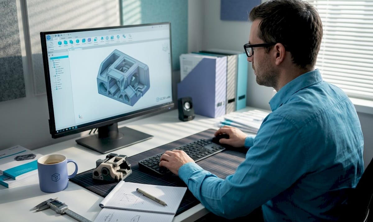
Even the most expensive FDM printer on the market cannot compensate for a poorly built CAD file. That counterintuitive reality catches a lot of product developers off guard, especially those who assume hardware upgrades are the fastest path to better prints. The truth is that CAD is the foundational step in every 3D printing workflow, converting your concept into a precise digital model that gets exported, sliced, and ultimately printed. Every tolerance, wall thickness, and mesh decision you make in CAD ripples forward into the physical part. Understanding that connection is what separates teams that iterate quickly from those stuck reprinting the same prototype three times.
Table of Contents
- How CAD shapes the 3D printing process
- Key CAD methodologies for print success
- Optimizing CAD files for stronger, more efficient parts
- Advanced considerations: Anisotropy, lattices, and hybrid processes
- Our take: Why great CAD still trumps expensive printers
- Ready to leverage pro-level CAD and 3D printing?
- Frequently asked questions
Key Takeaways
| Point | Details |
|---|---|
| CAD is foundational | Every 3D print project’s success begins and ends with how well you design and optimize your digital CAD model. |
| Follow DfAM best practices | Design for Additive Manufacturing rules like correct wall thickness and support planning prevent failed prints. |
| Optimize for performance | Tweaking orientation, infill, and mesh within CAD boosts strength and reduces production time and cost. |
| Account for advanced issues | Factoring in anisotropy and potential hybrid machining from the CAD stage yields better functional parts. |
| Invest in CAD expertise | Skillful CAD work typically enables more innovation and reliability than investing in costly printers alone. |
How CAD shapes the 3D printing process
CAD, or computer-aided design, is the software environment where your idea becomes a geometric, measurable model. It is not simply a drawing tool. In the context of 3D printing, CAD determines whether a part is even printable, and at what level of accuracy it will come out of the machine.
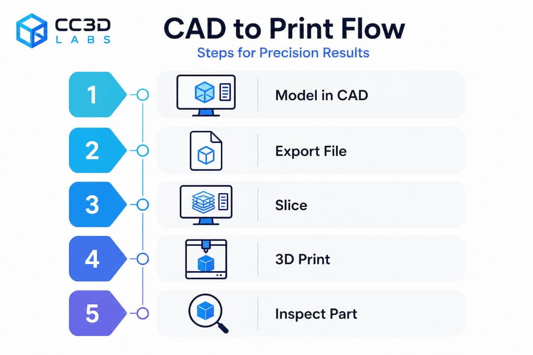
The workflow runs like this: you design a 3D model in CAD, export it as a machine-readable file, feed that into slicing software, and the slicer generates the toolpath your printer follows. The most common export format is STL (stereolithography), which approximates curved surfaces using triangular mesh facets. Higher triangle density produces smoother curves but inflates file size. Other formats like 3MF and STEP carry additional metadata such as color, scale, and assembly information, making them increasingly preferred for complex production jobs.
Here is why this matters in practice. An STL file with too-low resolution will print visible faceting on a curved medical enclosure or an aerodynamic intake. A mesh with non-manifold edges, gaps, or overlapping surfaces creates ambiguous geometry that slicers interpret incorrectly, leading to missing walls or hollow sections in a part that was supposed to be solid. Understanding the best CAD file formats for your specific workflow prevents a whole category of upstream errors before you ever hit print.
What CAD controls in 3D printing:
- Part geometry, including all wall thicknesses and internal features
- Surface topology and mesh quality
- Assembly fit and tolerancing
- Export format and resolution
- Whether geometry is valid and printable without repair
“CAD directly impacts print quality, precision, and success. The wrong design decisions create failures that no printer setting can fix.”
The key shift in mindset is treating CAD not as a design tool but as a manufacturing specification tool. Every decision you make in the model is a decision about how the printer will behave layer by layer.
Key CAD methodologies for print success
Design for additive manufacturing, commonly called DfAM, is the discipline of shaping CAD decisions around the specific constraints and advantages of 3D printing. It is distinct from design for injection molding or machining, and applying the wrong framework causes obvious problems.
The
core DfAM practices every engineer should internalize include minimum wall thickness guidelines, overhang management, hole geometry, stress-relief features, and watertight meshes. These are not aesthetic preferences. They are parameters grounded in how filament or resin behaves during deposition or curing.
Critical DfAM parameters for FDM and SLA:
- Minimum wall thickness: 1.0 to 2.0mm for FDM, 0.5 to 1.0mm for SLA
- Overhang angle: Keep overhangs under 45 degrees from vertical to avoid drooping without supports
- Teardrop holes: Orient vertical holes as teardrops to eliminate bridging failure at the top
- Fillets and chamfers: Add internal fillets to corners to reduce stress concentrations and delamination risk
- Mesh integrity: All surfaces must form a closed, watertight volume with no holes, gaps, or non-manifold edges
| DfAM Parameter | FDM Guideline | SLA Guideline |
|---|---|---|
| Minimum wall thickness | 1.2 to 2.0mm | 0.5 to 1.0mm |
| Overhang angle | Less than 45° | Less than 30° |
| Minimum hole diameter | 2.0mm | 0.5mm |
| Fillet radius | 0.5mm minimum | 0.3mm minimum |
| Mesh type | Watertight, manifold | Watertight, manifold |
When designing reliable prints, overhang management is often where teams stumble first. A bracket arm designed without awareness of the printer’s 45 degree threshold will require heavy supports that are time-consuming to remove and often leave cosmetic or dimensional defects on the contact surface. Redesigning the arm with a chamfer instead of a perpendicular face eliminates the support entirely.
Pro Tip: When your geometry calls for a hole parallel to the build plate, model it as a teardrop shape pointing upward. The slicer will bridge the flat underside cleanly, and you end up with a more accurate bore than a standard circle produces.
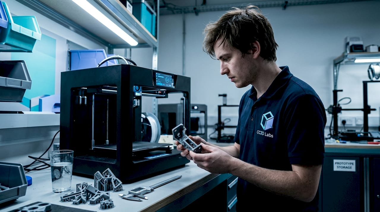
Watertight meshes deserve special attention because this is where many imported or converted models fail silently. A mesh that looks correct in CAD may contain microscopically open surfaces. Slicers either crash or generate malformed toolpaths from non-manifold geometry. Running a mesh repair check inside your CAD tool or a validator like Meshmixer before export is not optional on mission-critical parts. For more on how these rules translate into real outcomes, explore the print accuracy tips that guide our own production process.
Optimizing CAD files for stronger, more efficient parts
Once your model is geometrically sound and DfAM-compliant, the next layer of optimization focuses on performance. This is where CAD decisions directly affect mechanical strength, print time, and material cost simultaneously.
Step-by-step CAD optimization for production-ready parts:
- Analyze part orientation in the slicer before finalizing the model. The axis of greatest load should align with the XY build plane, not the Z axis.
- Identify all surfaces that would require supports and explore geometry modifications to minimize them.
- Choose between solid and lattice infill based on the part’s function. Load-bearing parts often need solid infill; structural housings can use gyroid or honeycomb lattice patterns without sacrificing rigidity.
- Set layer thickness based on your precision requirements. Thinner layers produce stronger, more accurate parts at the cost of print time.
- Confirm mesh resolution is high enough to accurately represent curves without over-bloating file size.
- Validate thermal settings in your CAD metadata or production notes if you are working with engineering-grade filaments like Nylon or PETG.
CAD pre-processing optimization analyzes part orientation to minimize supports, cut material use, and reduce print time. Tools like Siemens NX with DfAM modules can compare solid versus lattice infill configurations computationally, letting you evaluate structural performance before a single gram of filament is consumed.
The data on this is compelling. Empirical research on FDM shows that optimized CAD-printed PLA cubes reach compressive strength values around 31.4 MPa. Layer thickness is the single most influential parameter: a low layer thickness of 0.15mm combined with a high extruder temperature of 225 degrees Celsius produces the maximum combined performance index across strength and surface quality.
| Configuration | Layer Thickness | Extruder Temp | Compressive Strength |
|---|---|---|---|
| Optimized | 0.15mm | 225°C | ~31.4 MPa |
| Standard | 0.2mm | 210°C | ~24 MPa |
| Low quality | 0.3mm | 200°C | ~18 MPa |
This is not trivial. A 30 to 40 percent difference in part strength comes from CAD and process settings, not from switching to a more expensive printer. When you are developing functional prototypes or end-use parts, refer to manufacturing-grade methods to understand how these optimization principles apply at production scale. For teams new to this level of detail, a step-by-step prototype guide can bridge the gap between concept and validated part.
Advanced considerations: Anisotropy, lattices, and hybrid processes
For engineers pushing the mechanical limits of 3D printed parts, three topics demand serious CAD-level attention: anisotropy, lattice structure design, and hybrid manufacturing workflows.
Anisotropy refers to the directional variation in mechanical properties that FDM parts exhibit by default. Because material is deposited in layers, bonds between layers are inherently weaker than bonds within a layer. FDM anisotropy can result in a strength drop of up to 70 percent in the Z axis compared to the XY plane. In CAD terms, this means that a part carrying tensile loads in the Z direction will fail at a fraction of the force a same-geometry machined metal part would tolerate.
The CAD response to anisotropy is deliberate orientation strategy. You map the dominant load vectors onto the XY plane during the design phase, not as an afterthought during slicing. In some cases, this means splitting a part into two components that are printed separately and bonded, rather than printing a single piece in an unfavorable orientation.
Lattice structures offer compelling advantages for weight reduction in aerospace, robotics, and medical devices. A gyroid lattice can maintain 70 to 80 percent of a solid part’s stiffness at 40 percent of the material volume. However, internal lattices create a support removal challenge that most standard post-processing tools cannot address cleanly.
Key points for CAD-level lattice design:
- Define lattice cell size relative to nozzle diameter. Cells too small for the nozzle diameter will not print accurately.
- Avoid lattice regions adjacent to mating surfaces that require dimensional precision.
- Include drain holes in enclosed lattice zones to allow powder or resin evacuation in SLS and SLA processes.
- Simulate load distribution before committing to a cell pattern. Not all lattice geometries perform equally under all load types.
Pro Tip: If you are designing a lattice for structural lightweighting, run an FEA (finite element analysis) pass inside your CAD tool before exporting. Topology optimization outputs combined with lattice infill give you a data-backed starting point instead of an educated guess.
Hybrid manufacturing recognizes that 3D printing alone does not always achieve the tight tolerances that functional parts require. Post-print CNC machining on bearing surfaces, threaded holes, and mating faces is increasingly common in precision applications. This means your CAD model needs to include machining allowances, datum references for fixturing, and feature flags that differentiate printed surfaces from machined surfaces. Planning these details in CAD from the start avoids costly reprints and setup errors downstream. For guidance on balancing print complexity with production volume, the tips for low-volume production are directly applicable here.
Our take: Why great CAD still trumps expensive printers
We work with product developers and engineers across a wide range of industries, and one pattern shows up consistently: teams that struggle with print quality are almost always struggling with CAD quality first. The printer is rarely the problem. A printer running with a well-optimized, DfAM-compliant file will outperform a top-shelf machine running a poorly constructed model every single time.
The uncomfortable reality is that most 3D print failures, including warping, delamination, dimensional inaccuracy, and weak mechanical performance, are downstream effects of decisions made in CAD, not printer malfunctions. Engineers who understand DfAM, mesh integrity, orientation strategy, and material behavior at the design stage spend dramatically less time troubleshooting and iterating. Their first print is often their last prototype before production.
There is also an important counterargument worth naming honestly. As hybrid manufacturing research makes clear, 3D printing excels at prototyping and low-volume production, but scaling to true production volumes for complex, precision-critical parts often still requires integration with traditional machining. CAD skills become even more valuable in that hybrid context because you are designing simultaneously for two very different manufacturing constraints.
Our recommendation is this: invest the time to master your CAD workflow before you consider upgrading your printer. The return on that investment is higher, more transferable, and more immediately visible in print outcomes. Understanding why quality matters at the design stage is what gives you repeatable results, not a more expensive machine.
Ready to leverage pro-level CAD and 3D printing?
Putting these CAD principles into practice requires both expertise and the right production environment. At CC 3D Labs, we specialize in bridging the gap between your digital design and a precisely printed physical part, whether you are developing a functional prototype or moving into batch production.

Our team works directly with professional 3D printing services optimized for engineering-grade accuracy, reviewing CAD files for DfAM compliance before a single layer is printed. Whether you need on-demand prototypes with fast turnaround or guidance on production-ready part design, we bring the technical depth to make your designs work the first time. Browse our CAD project gallery to see the range of complex, precise parts we produce for clients across industries, and reach out for a free estimate when you are ready to move from concept to part.
Frequently asked questions
Why is CAD so important in 3D printing?
CAD provides the exact digital blueprint that determines whether a part is printable, how accurate it will be, and whether it will meet mechanical requirements. As foundational workflow research confirms, poor CAD decisions lead directly to failed or inaccurate prints regardless of printer quality.
Which CAD features matter most for strong 3D printed parts?
Wall thickness, mesh watertightness, part orientation, and well-placed fillets are the most critical design factors. DfAM practice guidelines specify minimum wall thickness of 1 to 2mm for FDM, with overhangs kept under 45 degrees and fillets applied at all internal corners to reduce stress.
How does CAD affect print time and material use?
Part orientation and infill strategy are the two biggest levers. Pre-processing optimization tools can compare solid versus lattice infill configurations and evaluate orientation options to minimize support structures, material consumption, and total print time before the job starts.
Do I always need to redesign parts in CAD for 3D printing?
Nearly always, yes. Parts designed for injection molding or machining often include geometry that is unprintable or structurally weak when 3D printed. Adapting designs to 3D printing-specific rules in CAD is essential for achieving reliable dimensional accuracy and mechanical performance.
What are the biggest challenges with CAD in 3D printing?
The most common challenges are managing anisotropic mechanical properties through orientation strategy, ensuring fully watertight mesh geometry, and designing parts that account for hybrid post-print machining. FDM anisotropy alone can reduce Z-axis strength by up to 70 percent when load alignment is not addressed in CAD.