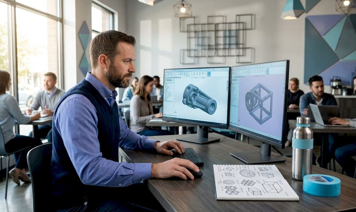
Engineer working on 3D drafting model at drafting table

Drafting Standards in 3D Modeling: Engineer’s Guide


TL;DR:

  • Drafting standards in 3D modeling establish rules for communicating design intent, geometry, and tolerances across workflows. They enable precise, unambiguous data exchange and prevent costly manufacturing errors by ensuring models are inspection-ready and organized properly. Enforcing these standards through software tools and workflow integration is essential for reliable, production-ready 3D models.

Drafting standards in 3D modeling are defined rule sets that govern how design intent is communicated, measured, and verified across every stage of a production workflow. These standards cover geometric dimensioning and tolerancing (GD&T), CAD data organization, and interoperability protocols. The two most referenced frameworks are ASME Y14.5, which defines symbolic tolerancing language for manufacturing, and ISO 10303 (STEP), which governs cross-platform data exchange. Without these standards, a model that looks correct on screen can produce parts that fail inspection on the shop floor.

What are drafting standards in 3d modeling?

Drafting standards in 3D modeling are the formal rules that define how geometry, dimensions, tolerances, and annotations are structured inside a CAD file. The industry term for this discipline is model-based definition (MBD), and it represents a shift away from 2D drawing packages toward fully annotated 3D models. CAD standards cover both appearance conventions such as layers, dimension styles, and symbols, and data organization rules that determine how files are named, structured, and exported.

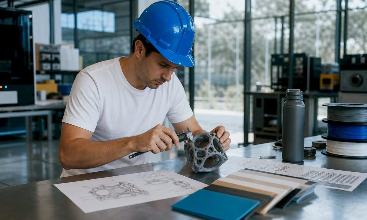
Hands examining 3D modeling drafting standards documents

A common misconception is that these rules are primarily about visual consistency. The real value lies in precise, unambiguous communication of size, shape, and tolerances that enables reliable manufacture and inspection. When a machinist or a coordinate measuring machine (CMM) reads a model, every symbol must carry exactly one interpretation. Ambiguity at this stage translates directly into scrap, rework, and cost overruns.

For 3D designers and engineers, understanding drafting standards means recognizing two parallel layers of rules. The first layer is semantic: GD&T symbols, datum references, and tolerance callouts. The second layer is structural: file naming, layer organization, metadata, and export format. Both layers must be correct for a model to move cleanly through a CAD modeling workflow.

Gd&t, data structure, and annotations explained

Geometric dimensioning and tolerancing (gd&t)

GD&T is the symbolic language that turns design intent into quantifiable requirements. ASME Y14.5 is the dominant standard in North America, and it defines symbols for flatness, cylindricity, true position, runout, and more than a dozen other geometric characteristics. Each symbol attaches a specific, measurable meaning to a feature. That specificity is what allows a CMM to verify a part automatically without a human interpreter.
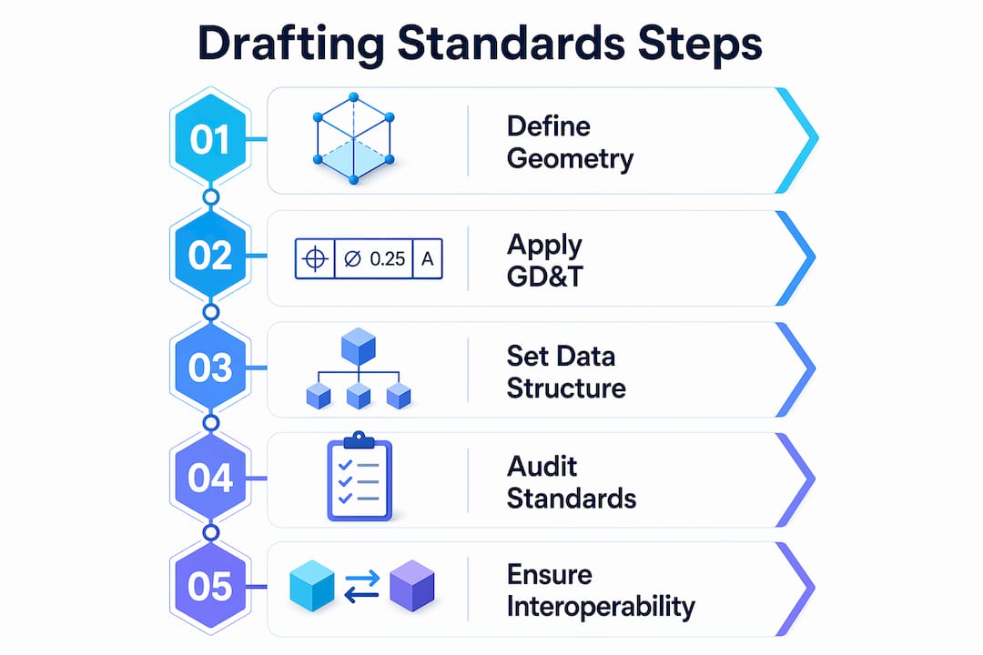
Infographic illustrating key steps in drafting standards process

MBD workflows embed these GD&T annotations directly into the 3D model as Product Manufacturing Information (PMI). Embedding PMI in 3D models enables CAD, PLM, CAM, and metrology systems to read design intent identically without intermediate translation. This eliminates the version-control problem that plagues organizations still maintaining parallel 2D drawing sets.

Pro Tip: When setting up PMI in software like Siemens NX or PTC Creo, attach every tolerance to a named datum reference frame from the start. Retrofitting datum structure onto a finished model costs far more time than building it correctly upfront.

CAD data structure and naming conventions

Data structure rules govern how a model is organized inside the file and across a project directory. Standard conventions include layer naming schemas, block or component naming, line weight assignments, and metadata fields like revision number and material specification. The National CAD Standard (NCS) and ISO standards both provide frameworks for these conventions, improving consistency and enabling data exchange between organizations.

Poorly organized CAD data passes visual checks but fails downstream. A model with correct geometry but misnamed layers or missing metadata will break automated manufacturing and inspection pipelines. Splitting standards into semantic rules (GD&T) and data-structure rules prevents this failure mode.

How CAD software enforces drafting standards

CAD platforms provide built-in tools to apply and audit drafting guidelines for 3D workflows. The enforcement mechanism matters as much as the standard itself. A style guide that lives in a PDF and is never checked produces inconsistent results across a team.

Autodesk AutoCAD uses standards files with the .DWS extension to enforce layer names, text styles, dimension styles, and line type properties. CAD standards auditing checks active drawings against these files and flags or automatically corrects any deviation. This workflow prevents standards drift in multi-user environments where individual designers make local modifications over time.

Here is how a typical CAD standards enforcement workflow runs in AutoCAD:

  1. A standards administrator creates a .DWS file that defines approved layers, styles, and properties for the project.
  2. The .DWS file is distributed to all team members and linked to active drawing files.
  3. Designers run the CHECKSTANDARDS command to audit their work before submission.
  4. AutoCAD flags non-conforming elements and offers automatic fixes where the correction is unambiguous.
  5. A project lead reviews the audit report and approves the file for release.

Pro Tip: Schedule automated standards checks as part of your file-save routine using AutoCAD’s notification settings. Catching a layer naming error at save time takes seconds. Catching it after a file has been handed to manufacturing takes hours.

The real power of drafting standards comes from enforceability through software auditing and team discipline, not from style guides alone. Organizations that rely on documentation without automated checks consistently produce non-conforming files.

Why interoperability standards matter for 3d collaboration

ISO 10303 (STEP) and cross-platform data exchange

ISO 10303, universally known as STEP, is the international standard for exchanging product model data across CAD, CAM, CAE, and PDM systems. STEP subdivides into approximately 700 standards and supports long-term archival as well as system-independent 3D model exchange. That breadth makes it the default format for aerospace, automotive, and defense supply chains where multiple organizations use different CAD platforms.

STEP preserves both geometry and topology, but semantic data preservation requires additional care. A model exported from CATIA and imported into SolidWorks may retain its surfaces while losing PMI annotations if the application protocol (AP) does not support that data scope. Interoperability depends on exporter and importer behavior and must be verified at each step in the toolchain.

Comparing key interoperability standards

Standard Primary Use Data Preserved Industry Focus
ISO 10303 (STEP) Cross-platform CAD exchange Geometry, topology, PMI (AP-dependent) Aerospace, automotive, defense
IFC (ISO 16739) Building and infrastructure models Geometry, spatial relationships, metadata Architecture, engineering, construction
IGES Legacy geometry exchange Geometry only General manufacturing (legacy)
OBJ / FBX Visualization and rendering Geometry, color, UV maps Media, gaming, visualization

For architecture, engineering, and construction (AEC) workflows, IFC (Industry Foundation Classes) fills the same role that STEP fills in mechanical engineering. IFC carries spatial relationships, component metadata, and building system data that STEP does not address. Choosing the wrong format for your industry means losing the semantic layer that makes a model useful beyond simple geometry.

Validating standards compliance at every handoff point is non-negotiable. Run format validation tools before sending files to partners or manufacturers. A translation error discovered after a part is machined is far more expensive than one caught during file review. For a practical look at CAD file format selection, the format choice directly affects how much of your standards-compliant data survives the transfer.

Best practices for production-ready 3d models

Drafting standards address how design intent is communicated. Production modeling standards address whether the geometry itself is manufacturable and pipeline-ready. Both sets of rules must be satisfied for a model to move from design to physical output without rework.

Professional 3D modeling standards emphasize clean topology, polygon efficiency, consistent edge flow, proper UV unwrapping, and the elimination of non-manifold geometry. These requirements apply whether the output is a rendered animation, a CNC toolpath, or a 3D print. Non-manifold geometry, for example, causes slicer software to fail silently, producing prints with missing walls or internal voids.

A production-ready model checklist covers the following areas:

  • Topology: Use quads as the primary polygon type. Triangles are acceptable at termination points. N-gons cause shading artifacts and should be resolved before export.
  • Scale and units: Set the correct real-world scale before modeling begins. A part modeled at the wrong unit system will print at the wrong size even if the geometry is perfect.
  • Naming conventions: Name every component, material, and UV channel descriptively. Generic names like “Mesh001” create confusion in assembly files and pipeline handoffs.
  • Non-manifold geometry: Run a manifold check in tools like Meshmixer, Netfabb, or the slicer’s built-in repair function before finalizing any model intended for physical production.
  • File organization: Group components logically, purge unused assets, and save in the format required by the downstream tool.
Quality Check Tool Pass Criteria
Manifold geometry Meshmixer, Netfabb Zero open edges or non-manifold faces
Scale verification CAD software ruler Matches engineering drawing dimensions
Naming convention Manual review or script All objects follow project naming schema
PMI completeness CAD PMI manager All features have tolerance callouts

These production standards integrate directly with drafting standards. A model with correct GD&T annotations but broken topology will still fail at the manufacturing stage. End-to-end quality assurance requires both layers to be correct. For engineers focused on tolerances in 3D printing, the connection between GD&T callouts and physical print accuracy is direct and measurable.

Key takeaways

Drafting standards in 3D modeling require both semantic precision (GD&T and PMI) and structural discipline (data organization and interoperability) to produce models that are reliable from design through manufacturing.

Point Details
GD&T is the core semantic layer ASME Y14.5 symbols turn design intent into machine-readable, verifiable requirements.
MBD replaces 2D drawings Embedding PMI directly in 3D models eliminates ambiguity and version-control problems.
Software enforcement is mandatory AutoCAD .DWS auditing and similar tools prevent standards drift across multi-user teams.
STEP governs data exchange ISO 10303 preserves geometry and PMI across platforms, but AP compliance must be validated.
Production standards complete the picture Clean topology, correct scale, and organized assets are required alongside drafting rules for production-ready output.

Where standards break down in real projects

Most standards failures I see at Cc3dlabs do not come from ignorance of ASME Y14.5 or ISO 10303. They come from the gap between knowing a standard and enforcing it consistently across a team under deadline pressure. A designer who understands GD&T perfectly will still skip datum references when a project is running late. That shortcut costs far more time downstream than it saved upfront.

The shift toward MBD is real and accelerating, but it creates a new failure mode. Teams that move tolerances and annotations from 2D drawings into 3D PMI sometimes assume the software handles validation automatically. It does not. PMI that is geometrically attached but semantically incomplete passes visual inspection and fails CMM verification. I have seen this exact problem delay production runs by days.

My practical recommendation is to treat standards enforcement as a workflow step, not a final review. Build .DWS checks, manifold validation, and PMI completeness reviews into the save and submit process. Make them automatic and non-optional. The teams that do this consistently produce fewer non-conforming files and spend less time on rework. The teams that treat standards as a checklist item at the end of a project spend a disproportionate amount of time fixing problems that were created weeks earlier.

The future of 3D design drafting rules points toward tighter integration between CAD, 3D printing, and metrology. As CAD integration drives printing precision, the standards embedded in your model become the direct input to both the printer and the inspection system. Getting those standards right is not a documentation exercise. It is the foundation of a reliable production process.

— Justin

How Cc3dlabs supports standards-compliant 3d production

When your model meets drafting and production standards, the path from file to finished part is fast and predictable. Cc3dlabs works with engineers and product developers near Philadelphia and worldwide to turn standards-compliant CAD files into precise, functional parts. The team reviews incoming models for production readiness, flags geometry issues before printing begins, and delivers parts that match the tolerances specified in your design.

https://cc3dlabs.com

Whether you need a single prototype or a batch production run, Cc3dlabs’ 3D printing services are built around the same quality standards covered in this guide. From filament-based FDM parts to professional handheld 3D scanning (accuracy to ~0.1 mm), every project starts with a free online estimate and direct design support. Submit your file and get a quote today.

FAQ

What are drafting standards in 3d modeling?

Drafting standards in 3D modeling are formal rule sets that govern how geometry, dimensions, tolerances, and annotations are structured in a CAD file. They include GD&T frameworks like ASME Y14.5 and data organization conventions that ensure models are clear, consistent, and production-ready.

What is gd&t and why does it matter for 3d models?

GD&T (Geometric Dimensioning and Tolerancing) is a symbolic language defined by ASME Y14.5 that communicates exact size, shape, and tolerance requirements for manufactured parts. It matters because it replaces ambiguous notes with machine-readable symbols that CMMs and CAM software can interpret without human interpretation.

What is the difference between STEP and IGES for CAD data exchange?

STEP (ISO 10303) preserves geometry, topology, and PMI annotations depending on the application protocol used, making it the current standard for cross-platform exchange. IGES is a legacy format that transfers geometry only and lacks support for semantic data like tolerances and metadata.

How does model-based definition (MBD) change drafting workflows?

MBD embeds GD&T annotations and PMI directly into the 3D model, eliminating the need for separate 2D drawing packages. This reduces ambiguity and allows CAD, CAM, and metrology systems to read design intent from a single source of truth.

What tools enforce CAD drafting standards across a team?

AutoCAD uses .DWS standards files to audit layer names, text styles, and dimension properties against approved project standards. Running the CHECKSTANDARDS command flags and corrects non-conforming elements before files are released to manufacturing or shared with collaborators.
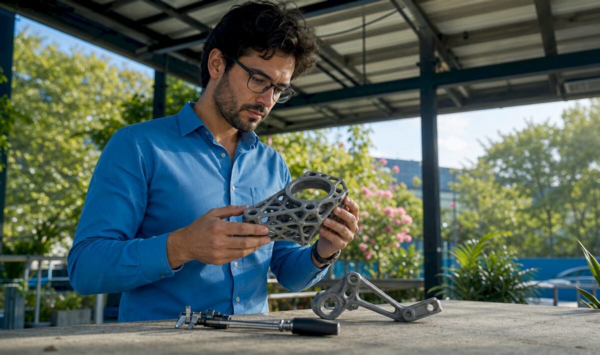

Engineer working on CAD modeling at drafting table

CAD Modeling Workflow 2026: Engineer’s Optimization Guide


TL;DR:

  • A modern CAD workflow in 2026 relies on disciplined parametric modeling, PLM-enforced version control, and 3MF exports to produce print-ready parts efficiently. Consistently sequencing assembly, validation, and detail features prevents costly rework and ensures reliable manufacturing outcomes. Process discipline, rather than software upgrades, remains the key to optimizing design and production efficiency.

A modern CAD modeling workflow is a structured sequence of design operations that, when executed correctly, reduces iteration time and produces print-ready geometry with fewer errors. For product developers and engineers targeting 3D printing efficiency in 2026, the difference between a functional workflow and a chaotic one comes down to three disciplines: parametric modeling in tools like SOLIDWORKS or CATIA, data management through PDM/PLM systems, and export practices built around the 3MF file format. Get those three right, and every downstream step from CAE validation to physical print becomes faster and more predictable.

What are the essential tools for a CAD modeling workflow in 2026?

The foundation of any efficient CAD design process in 2026 is software that supports parametric, feature-based modeling. SOLIDWORKS, CATIA, and Solid Edge are the three platforms most widely used in professional product development because each supports full constraint-driven geometry, assembly management, and direct integration with simulation and manufacturing tools. Choosing between them depends on industry context: CATIA dominates aerospace and automotive, SOLIDWORKS leads in mechanical product design, and Solid Edge offers strong sheet metal and frame capabilities.

Hands using graphic tablet for CAD design

Hardware matters more than most engineers admit. Complex assemblies with hundreds of components demand workstations with high single-core clock speeds, 32–64 GB of RAM depending on assembly size, and certified graphics cards from NVIDIA Quadro or AMD Radeon Pro lines. Running a 400-part assembly on an underpowered machine does not just slow you down. It introduces instability that corrupts rebuild sequences and forces manual intervention.

PDM/PLM systems replace shared folders as the backbone of file management. They enforce check-in/check-out protocols, maintain full version history, and apply naming conventions automatically. Without them, teams routinely work on outdated geometry and produce conflicting revisions that cost days to reconcile.

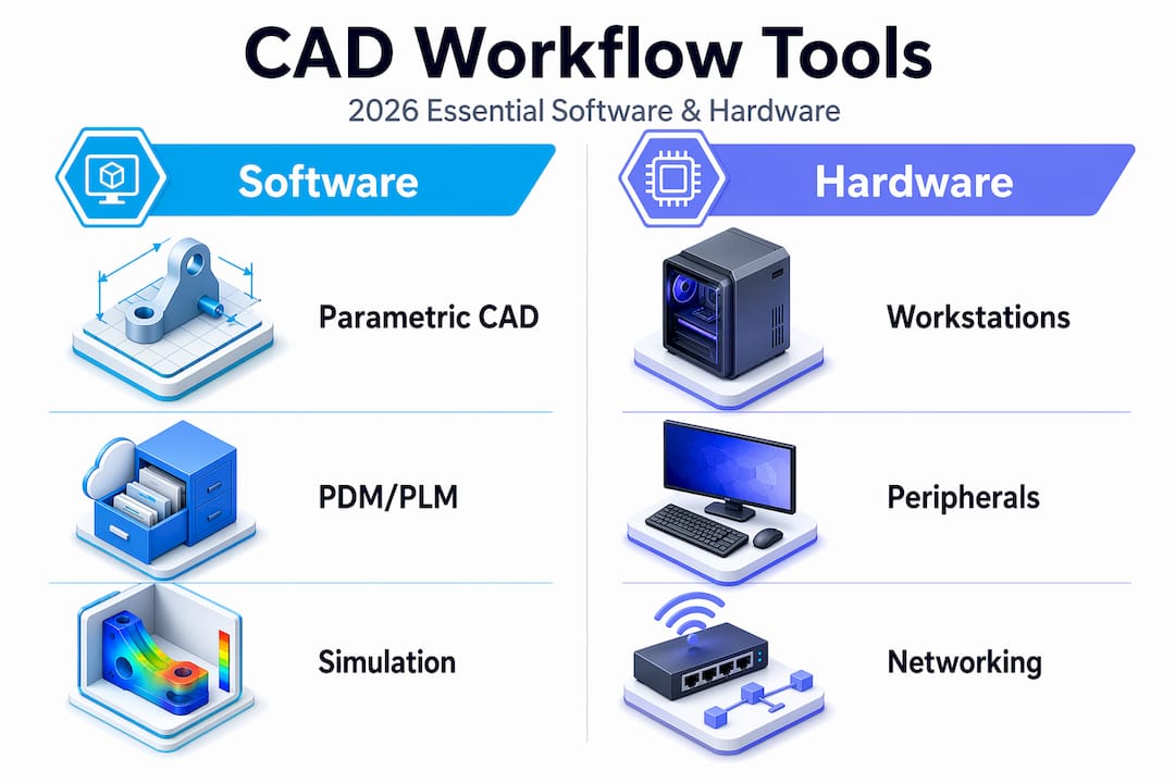
Tool category Recommended options Primary benefit
Parametric CAD SOLIDWORKS, CATIA, Solid Edge Constraint-driven design and assembly management
PDM/PLM SOLIDWORKS PDM, Windchill, Teamcenter Version control and change management
Simulation (CAE) ANSYS, Abaqus, SOLIDWORKS Simulation Structural, thermal, and fluid validation
Slicing/export PrusaSlicer, Bambu Studio, Chitubox 3MF and G-code generation for printing

Infographic comparing CAD software and hardware tools

Pro Tip: Keyboard shortcuts and templates can improve productivity by 20 to 30% in professional CAD environments. Build a custom startup template with your standard units, material libraries, and drawing formats before starting any new project.

How to structure your CAD workflow steps for 3D printing projects

A well-structured CAD workflow follows a deliberate sequence. Skipping steps or reordering operations to save time upfront almost always creates larger problems during validation and export. The following sequence applies to parametric solid modeling for additive manufacturing projects.

  1. Define the assembly structure first. Before modeling a single part, map out the functional subassemblies. Identify which components move, which are fixed, and where the critical interfaces are. This prevents structural rework later when parts fail to mate correctly.

  2. Create master sketches to drive parametric design. A master sketch is a 2D layout sketch at the assembly level that defines key dimensions, reference planes, and spatial relationships. Changes to the master sketch propagate through all dependent parts automatically, which is the core advantage of parametric modeling.

  3. Model base volumes before adding detail features. Build the primary solid geometry first: extrusions, revolves, and lofts that define the overall shape. Leave fillets, chamfers, threads, and surface textures for later. Applying fillets too early creates large rebuild penalties and should be postponed until base volumes are fully validated.

  4. Validate geometry before detailing. Run interference checks and confirm wall thicknesses meet your printer’s minimum requirements before adding any cosmetic or functional detail features. Catching a wall thickness violation at this stage takes minutes. Catching it after threading and filleting takes hours.

  5. Add detail features in a controlled sequence. Apply threads, fillets, chamfers, and surface finishes only after base geometry passes validation. Group similar operations together to minimize rebuild cycles.

  6. Embed review steps throughout, not just at the end. Formal review steps embedded throughout the process reduce rework iterations and drawing errors significantly. Schedule a peer review after step 3 and again after step 5.

Pro Tip: For complex assemblies, use a top-down modeling approach where the master sketch lives at the assembly level. For simpler parts, bottom-up modeling is faster and easier to manage.

Workflow approach Best for Key trade-off
Top-down (master sketch driven) Complex multi-part assemblies Higher setup time, lower rework risk
Bottom-up (independent parts) Simple parts and small assemblies Faster start, harder to propagate global changes
Hybrid Mid-complexity products with modular subassemblies Balances speed and control

How does CAD integrate with CAM, CAE, and PLM for manufacturing?

CAD is the source of truth for geometry and tolerances. Every downstream system, whether it is a simulation solver or a CNC toolpath generator, reads from the CAD model. That dependency makes the quality of the CAD model the single largest variable in manufacturing outcome. CAD-CAM-CAE integration through PLM coordination ensures that only validated designs proceed to production.

The integration loop works as follows:

  • CAD defines geometry, tolerances, and material specifications.
  • CAE (tools like ANSYS or SOLIDWORKS Simulation) validates structural, thermal, and fluid performance against design requirements.
  • CAM (tools like Mastercam or Fusion 360 CAM) generates toolpaths and manufacturing instructions from validated CAD geometry.
  • PLM (Windchill, Teamcenter, or SOLIDWORKS PDM) coordinates the gating between each phase, controls who can approve transitions, and triggers re-validation when edits occur after approval.

The gating function of PLM is what most teams underuse. Without formal gates, engineers edit geometry post-CAE without triggering a new simulation run. That gap between the validated model and the manufactured model is where costly field failures originate. Every geometry change after CAE sign-off must restart the validation cycle. PLM enforces that rule automatically when configured correctly.

Phase Primary tool Output
Geometry definition SOLIDWORKS, CATIA Parametric solid model with tolerances
Performance validation ANSYS, Abaqus Simulation report and pass/fail status
Manufacturing prep Mastercam, Fusion 360 CAM Toolpaths, G-code, or print instructions
Change control Windchill, Teamcenter Approved revision with audit trail

What file formats optimize CAD models for 3D printing?

3MF is the preferred format for additive manufacturing in 2026. Unlike STL, which stores only surface triangles with no color, material, or metadata, 3MF packages geometry, slicer settings, color assignments, material specifications, and project information inside a single ZIP/XML container. That means a 3MF file sent to a printer or service bureau carries everything needed to reproduce the design intent without a separate specification document.

STL remains common because legacy workflows depend on it, but its limitations create real problems. STL files carry no unit information, no material data, and no tolerance context. A print service receiving only an STL file must make assumptions about scale, orientation, and material that the designer never intended. Those assumptions cause the “mysterious” print failures that engineers spend hours diagnosing.

The right export package for any serious 3D printing project includes three files. First, the 3MF for the printer or service bureau. Second, a STEP file for cross-software review and manufacturing quotes, since STEP preserves solid geometry and works across all major CAD platforms. Third, a 2D drawing with GD&T callouts that documents tolerances, critical surfaces, and inspection requirements.

Pro Tip: Before exporting, run a mesh quality check inside your CAD tool or a dedicated utility like Netfabb or Meshmixer. Look for non-manifold edges, inverted normals, and gaps in the mesh. These defects are invisible in the CAD environment but cause slicer failures that are hard to trace back to their source. Learn more about optimizing CAD file formats for additive manufacturing.

What common mistakes slow down CAD modeling efficiency?

The most expensive mistake in parametric CAD is applying heavy operations too early. Moving fillets and threads to the end of the feature tree is not just a style preference. Reversing detail and main shape operations causes considerable time loss. For complex models with 400 or more cavities, restructuring the feature order has reduced computation time from over an hour to seconds.

Version control failures are the second most common source of rework. Engineers working from shared folders without PDM often edit the wrong revision, overwrite a colleague’s changes, or submit geometry that was superseded two days earlier. Strong data management practices like templates, naming conventions, and version control underpin sustainable workflow efficiency. There is no software feature that compensates for absent version discipline.

GD&T errors are subtler but equally damaging. Tolerance attachments and derived datum controls are often not automatically validated by CAD constraint solvers, which means incorrect or missing GD&T semantic attachments require engineering review even in automated workflows. Choosing between ISO 1101 and ASME Y14.5 is not a minor formatting decision. It directly affects inspection outcomes and manufacturing conformance, particularly for aerospace and medical applications.

  • Apply fillets, chamfers, and threads only after base geometry validation passes.
  • Use PDM check-in/check-out for every file, even on solo projects.
  • Verify GD&T callouts against the applicable standard (ISO 1101 or ASME Y14.5) before releasing drawings.
  • Run interference analysis at the assembly level before detailing individual parts.
  • Automate repetitive exports with macros to eliminate manual errors and save time.

“Most CAD workflow efficiency gains come from disciplined process improvements rather than solely new software features.” — Efficient modeling workflow guide

Key takeaways

An optimized CAD modeling workflow in 2026 requires parametric discipline, PLM-enforced version control, and 3MF-based exports to produce reliable, print-ready geometry at speed.

Point Details
Structure before modeling Define assembly hierarchy and master sketches before creating any part geometry.
Delay detail features Apply fillets, threads, and chamfers only after base volumes pass interference checks.
Use PDM/PLM for all files Version control through Windchill or SOLIDWORKS PDM prevents costly revision conflicts.
Export 3MF plus STEP Send 3MF for printing and STEP with 2D drawings for manufacturing quotes and review.
Gate every phase PLM must trigger re-validation after any geometry edit post-CAE approval.

Why process discipline beats software upgrades every time

I have watched teams spend significant budget on new CAD seats and simulation licenses, then wonder why their iteration cycles did not shorten. The answer is almost always the same. The software was not the bottleneck. The process was.

The most impactful change I have seen in any CAD environment was not a software upgrade. It was a team that committed to top-down assembly structuring and master sketch discipline. Their rebuild times dropped from hours to minutes on assemblies that had previously been nightmares to modify. The tools were the same. The sequence changed.

What I tell every product developer I work with is this: map your current workflow on paper before touching any settings. Identify where you are applying operations out of order, where files live outside PDM, and where GD&T callouts are being added as afterthoughts. Those three areas account for the majority of rework in most teams I have seen.

The future CAD workflows that will define 2026 and beyond are not defined by AI-assisted sketching or cloud rendering. They are defined by teams that treat their modeling sequence as a living process, review it regularly, and enforce it consistently. Technology amplifies discipline. It does not replace it.

— Justin

How Cc3dlabs supports your CAD-to-print workflow

When your CAD model is ready for production, the transition from file to physical part should be frictionless. Cc3dlabs specializes in handling complex CAD files optimized for additive manufacturing, accepting 3MF, STEP, and native formats to preserve your design intent from model to print.

https://cc3dlabs.com

Whether you need a single functional prototype or a batch of production parts, Cc3dlabs’ professional 3D printing services near Philadelphia cover multi-color printing, professional handheld 3D scanning (accuracy to ~0.1 mm), and design support for engineers who need accurate, durable results fast. If you want to see how 3D printing drives product innovation in 2026, the Cc3dlabs team is ready to take your optimized CAD files and turn them into parts that perform.

FAQ

What is a CAD modeling workflow?

A CAD modeling workflow is a structured sequence of design steps that takes a product from concept geometry to a validated, export-ready model. It includes assembly structuring, parametric modeling, simulation validation, and file export for manufacturing or 3D printing.

What is the best CAD software for 3D printing in 2026?

SOLIDWORKS and Fusion 360 are the most widely used platforms for 3D printing-focused design because both support parametric modeling and direct 3MF export. CATIA and Solid Edge are preferred in aerospace and automotive contexts where tighter PLM integration is required.

Why is 3MF better than STL for 3D printing?

3MF stores geometry alongside colors, materials, slicer settings, and project metadata inside a single ZIP/XML package, while STL stores only surface triangles with no unit or material information. That metadata gap in STL files causes scale errors and print failures that 3MF eliminates by design.

How does PLM improve CAD workflow efficiency?

PLM systems like Windchill and Teamcenter gate each design phase, enforce re-validation after geometry edits, and maintain a full audit trail of approved revisions. Without PLM, teams routinely manufacture from outdated or unapproved geometry, which is the leading cause of costly production rework.

When should you apply fillets and chamfers in a CAD model?

Apply fillets, chamfers, and threads only after base geometry has passed interference checks and wall thickness validation. Adding detail features too early creates rebuild penalties that can extend computation time from seconds to over an hour on complex assemblies.

3D modeler working in bright studio

What Is Advanced 3D Modeling: Techniques and Applications


TL;DR:

  • Advanced 3D modeling involves precision parametric design, organic sculpting, and AI workflows that ensure models are production-ready. It relies on geometric representations like polygon meshes, NURBS, and parametric constraints to create models that survive manufacturing, animation, and visualization processes. Mastering topology, UV mapping, and hybrid workflows enables professionals to produce high-quality models efficiently across industries.

Advanced 3D modeling is far more than placing shapes on a digital canvas. When you ask what is advanced 3D modeling, the real answer involves precision parametric design, organic sculpting, intelligent topology management, and AI-assisted workflows that together produce models ready for manufacturing, animation, and architectural visualization. At its core, 3D models represent shape, size, and texture through polygon meshes and mathematical surfaces. This article breaks down the techniques, tools, real-world applications, and emerging trends you need to understand if you want to apply advanced modeling skills to serious design and prototyping work.

Table of Contents

Key Takeaways

Point Details
Beyond basic shapes Advanced 3D modeling combines parametric precision, sculpting, and AI workflows rather than simple geometry creation.
Technique diversity matters Professionals merge CAD, NURBS, and freeform sculpting in hybrid workflows to solve complex spatial and artistic problems.
AI assists but does not replace AI tools accelerate base modeling and texturing while skilled artists handle refinement and production standards.
Applications span industries Manufacturing, gaming, architecture, and virtual production all rely on advanced modeling for prototyping and visualization.
Fundamentals drive AI success Mastering topology and UV mapping remains critical even when AI-generated assets enter the pipeline.

What advanced 3D modeling actually means

Most people associate 3D modeling with creating a rough shape and slapping a texture on it. Advanced 3D modeling sits in a completely different category. It is the discipline of constructing digital geometry with intentional precision, structural logic, and production readiness baked into every decision you make from the first polygon to the final export.

The mathematical foundation matters here. Advanced models rely on three primary geometric representations:

  • Polygon meshes: Grids of vertices, edges, and faces that define surface geometry. Fast to render but require careful topology management to deform cleanly and print accurately.
  • NURBS (Non-Uniform Rational B-Splines): Mathematically smooth curves and surfaces used heavily in industrial CAD. They produce watertight, precise geometry ideal for engineering tolerances.
  • Parametric constraints: Rules and relationships embedded in the model so that changing one dimension automatically updates dependent features throughout the entire design.

The gap between basic and advanced 3D modeling is not just about software complexity. It is about whether your model can survive a real production pipeline. An advanced model transfers cleanly between software environments, holds up under manufacturing tolerances, animates without mesh artifacts, and can be iterated without rebuilding from scratch.

Advanced modeling software today covers a spectrum from parametric CAD platforms to freeform sculpting environments. Each serves a different purpose, and understanding when to use which is part of what separates professionals from beginners. AI’s emerging role in this field is shifting artists from manual geometry creation toward high-level prompt engineering and iterative refinement, but the underlying principles of good modeling have not changed.

Pro Tip: If you are evaluating whether your modeling skills qualify as “advanced,” ask yourself this: can your models survive a file format conversion, a topology audit, and a manufacturing review without significant rework? If the answer is no, that is your learning roadmap.

Advanced 3D modeling techniques and workflows

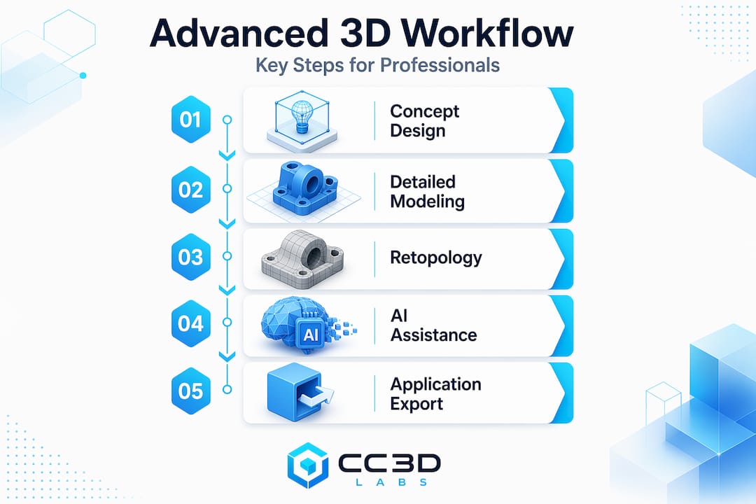
The techniques that define professional-grade advanced 3D modeling are not learned in isolation. They layer on top of each other in workflows that combine structure, detail, and artistic expression. Here is how the major techniques build on each other in practice:

  1. Parametric modeling. You define geometry through constraints and relationships rather than direct manipulation. Change the wall thickness of a housing component and every connected feature updates automatically. This is the backbone of product design and engineering work, where parametric and generative design solve spatial problems with precision rather than aesthetic guesswork.

  2. Freeform sculpting. Digital sculpting tools let you manipulate virtual clay-like geometry using symmetry, layers, and dynamic remeshing. The priority at this stage is artistic freedom before technical constraints. Characters, organic products, and architectural details all benefit from sculpting workflows that capture nuance no parametric tool can match.

  3. Hybrid CAD-sculpt integration. This is where advanced workflows get genuinely complex. Hybrid workflows use CAD for structural precision and sculpting tools for high-detail organic surfaces, requiring careful translation between NURBS and polygon mesh formats. A product designer might build the structural shell in a CAD environment, export to a sculpting tool for surface detailing, and then retopologize before returning to CAD for final manufacturing prep.

  4. Topology and UV mapping. Clean topology means your mesh deforms predictably for animation and prints without internal geometry conflicts. UV mapping unfolds the 3D surface into a 2D space so textures apply correctly without stretching. These two disciplines are unglamorous but are the difference between a model that works and one that causes problems downstream.

  5. Texture baking and iterative refinement. Baking transfers high-resolution surface detail from a dense sculpt onto a lighter mesh, preserving visual quality without the polygon count that would slow rendering or fail in a game engine. Iterative refinement means reviewing the model at each stage, catching problems before they compound.

Pro Tip: Learn retopology before you need it urgently. Most professionals wish they had learned proper edge flow earlier. Bad topology is the most common reason a client’s model gets rejected at the manufacturing or rigging stage.

AI tools are now entering every step of this workflow. AI-assisted features like automated retopology and intelligent mesh deformation compress timelines significantly. Tools like Meshy.ai produce multiple model variations rapidly for stylized and mid-polygon assets, making iteration faster than ever for the right project types.

Designer using AI retopology tools on 3D mesh

Benefits and practical applications

Understanding the benefits of advanced 3D modeling is straightforward once you see where it connects to real project outcomes. Advanced modeling is not a luxury skill. It is how serious design and manufacturing work gets done.

Here is where the practical value shows up most clearly:

  • Product prototyping. Advanced modeling improves manufacturing and design processes by enabling precise, adaptable, high-fidelity models. Instead of discovering a fit problem during physical assembly, you catch it in the parametric model and update the design in minutes.
  • Architecture and spatial design. Architects using parametric tools can test structural configurations and aesthetic variations within the same model file, reducing costly design revisions. Digital tools in construction can reduce project costs measurably when modeling accuracy drives early-stage decisions.
  • Gaming and virtual production. Character artists combine sculpting for hero detail and retopology for real-time game engines. The same pipeline feeds into virtual production environments where physical accuracy and visual fidelity both matter.
  • Manufacturing visualization. Engineers use advanced 3D models to simulate assembly sequences, stress test components virtually, and communicate design intent across global teams before a single physical part is produced.
Application Area Primary Modeling Approach Key Benefit
Product design Parametric CAD Precise tolerances, fast iteration
Character and creature art Freeform sculpting Organic detail, artistic control
Architecture Hybrid parametric and mesh Spatial problem solving, visualization
3D printing and prototyping CAD to mesh pipeline Printable geometry, manufacturing accuracy
Gaming and real-time environments Retopologized sculpts Optimized poly count, clean deformation

The creative freedom argument is real too. Sculpting gives artists control that box-modeling never could. But the most powerful outcome of advanced 3D modeling is speed with quality. When your workflow is solid, you can go from concept to print-ready or render-ready file faster than any earlier generation of designers.

Challenges and what comes next

Advanced 3D modeling is not a skill you pick up over a weekend. The challenges are genuine, and the field is changing fast enough that even experienced modelers need to keep adapting.

The persistent technical challenges include:

  • Topology cleanup. AI-generated models often require significant retopology before they are production ready. Post-generation cleanup includes retopology and fixing non-manifold geometry to ensure compatibility with rendering engines and 3D printing workflows.
  • Format interoperability. Moving models between CAD, sculpting, and rendering environments often introduces data loss or geometry errors. Managing NURBS and polygon meshes without losing design intent is one of the most technically demanding aspects of hybrid workflows.
  • Skill gaps in texture pipelines. Junior artists often need mentorship to master topology, UV mapping, and texture pipelines even when they are working with advanced software. The tools do not teach the judgment.

“AI effectively lowers the skill floor and compresses timelines significantly, but the ceiling is still defined by the human who refines and directs the work.”

Looking forward, the field is moving toward real-time sculpting in collaborative cloud environments, spatial computing interfaces that let designers manipulate geometry physically, and AI that can handle increasingly complex base model generation. The artists who will succeed are those treating AI as a skilled collaborator rather than a replacement for foundational knowledge.

My take on mastering advanced 3D modeling in 2026

Infographic showing main steps in advanced 3D modeling workflow

I have watched a lot of people approach advanced 3D modeling the same way. They jump to the most sophisticated software they can find, spend weeks learning its interface, and then produce work that falls apart the moment a client needs it to be printable or rigged. What I have learned is that the fundamentals are not the boring part. They are the part that makes everything else possible.

The most capable modelers I know are not the ones who adopted AI tools first. They are the ones who understand why topology flows a certain way, what happens when geometry is non-manifold, and how UV seams affect texture quality. Because they understand those things, they can direct AI tools effectively and fix what the automation gets wrong. My honest advice: spend real time on topology, spend real time on the math behind your surfaces, and then let AI speed up the work you already understand. The 3D modeling and CAD project gallery at Cc3dlabs is a good place to see what production-ready advanced modeling actually looks like in practice.

— Justin

Turn your advanced models into physical reality with Cc3dlabs

https://cc3dlabs.com

Advanced 3D modeling is where precision design begins. But the real test of any model is whether it survives contact with the physical world. Cc3dlabs, located near Philadelphia, works directly with designers, engineers, and product developers to take advanced 3D models through to high-quality printed parts. Their 3D printing services cover everything from single prototypes to batch production runs, with filament-based printing capable of meeting tight tolerances for functional parts. They also offer professional handheld 3D scanning (accuracy to ~0.1 mm), which feeds directly into advanced modeling workflows when you need to capture existing geometry accurately. If you are ready to validate your design in the real world, Cc3dlabs offers free online estimates and local pickup for Philadelphia-area clients.

FAQ

What is advanced 3D modeling?

Advanced 3D modeling is the practice of creating production-ready 3D geometry using parametric constraints, freeform sculpting, and topology management techniques that go beyond basic shape creation. It encompasses both CAD-driven precision and artistic sculpting workflows, often combined in hybrid pipelines.

How is advanced 3D modeling different from basic 3D modeling?

Basic 3D modeling produces simple geometry for visualization purposes. Advanced 3D modeling produces models with clean topology, accurate tolerances, proper UV mapping, and the structural integrity needed for animation, manufacturing, or 3D printing.

What software is used for advanced 3D modeling?

Professionals use a range of advanced modeling software depending on the application, including parametric CAD platforms for engineering and sculpting tools for organic design. Many advanced workflows combine multiple software environments, translating between NURBS-based and polygon-based geometry.

How does AI fit into advanced 3D modeling workflows?

AI tools generate base models and automate tasks like retopology and mesh deformation, but post-generation cleanup is still required for production-ready assets. AI shifts the artist’s role toward high-level direction and refinement rather than eliminating the need for technical skill.

How do I learn advanced 3D modeling?

Start by building a strong foundation in topology, UV mapping, and at least one parametric CAD platform. Then layer in sculpting tools and hybrid workflows. Working with real production constraints, such as preparing models for 3D printing, accelerates learning faster than purely artistic projects.

3D designer working on office CAD workstation

3D modeling process for businesses: a step-by-step guide


TL;DR:

  • Flawed 3D models incur high costs and delays when errors are discovered late in manufacturing. Implementing a structured workflow, including validation gates and proper file formats, ensures geometry integrity and reduces rework. An integrated PLM system connects design stages, enabling simultaneous processes and maintaining a single source of truth for efficient product development.

Flawed 3D models are expensive. A geometry error caught after parts are machined can set a product launch back weeks and cost thousands in rework. Yet most manufacturing businesses still treat the 3d modeling process for businesses as an informal, tool-by-tool activity with no standardized handoffs, no validation gates, and no version control. The result is predictable: duplicate revisions, miscommunication between design and manufacturing teams, and prototypes that fail on the first print run. This guide gives you a structured, stage-by-stage workflow to fix that.

Table of Contents

Understanding the 3D modeling workflow for manufacturing businesses

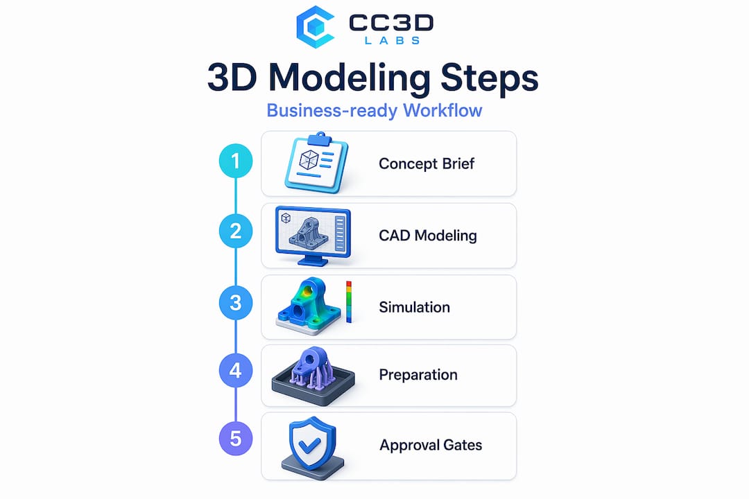
Every reliable product development cycle runs on a defined sequence of stages. The business-ready 3D modeling workflow follows this structure: Concept and brief, CAD geometry design, CAE (computer-aided engineering) simulation and validation, CAM (computer-aided manufacturing) planning, then manufacturing with ERP cost tracking. Product lifecycle management (PLM) sits above all of it as the system of record, connecting every tool and every team.

Without PLM as the connective layer, these stages operate in silos. A CAD designer updates a wall thickness. The CAE analyst runs stress simulations on the old version. The CAM programmer generates toolpaths from a model that no longer exists. That chain of disconnected handoffs is where most manufacturing delays originate.

The five core stages at a glance:

Stage Tool Primary output
Concept and brief Requirements docs, sketches Design intent and constraints
CAD geometry design SOLIDWORKS, Fusion 360, Creo Solid 3D model files
CAE validation ANSYS, Nastran, SimScale Simulation reports
CAM planning Mastercam, HSMWorks Toolpaths and G-code
Manufacturing and cost tracking ERP, PLM Production records and BOM

Infographic with 3D modeling workflow steps

Approval gates between each stage are not bureaucratic overhead. They are cost-control mechanisms. A model that fails CAE validation should never reach CAM programming. Enforcing that boundary through PLM approval workflows eliminates the most expensive class of rework: discovering structural problems after tooling has already been produced.

For businesses scaling toward production, reading a manufacturing-grade 3D printing guide alongside this workflow will clarify how design decisions upstream affect print quality and production yield downstream.

Preparing 3D models for manufacturing: ensuring geometry validity and quality

A valid workflow means nothing if the geometry inside your models is broken. Before any model reaches slicing software or a CNC controller, it must pass two geometric tests: it must be watertight and it must be manifold.

Engineer examining 3D printed part for issues

Watertight means the model has no holes or gaps in its surface. Think of it as a sealed container. If you filled it with water, nothing would leak. Manifold means every edge in the mesh is shared by exactly two faces and no more. These are not cosmetic requirements. A model that fails either condition causes slicer failures including missing layers or infinite calculation loops, because the slicing software cannot determine where the inside of the object begins and ends.

Non-manifold edges and open shells create ambiguous topology, which forces slicers into undefined states. The practical consequences range from incomplete prints to parts with internal voids that only reveal themselves under load testing.

Common geometry problems that cause manufacturing failures:

  • Open shells and gaps at seams between joined bodies
  • Non-manifold edges where three or more faces share one edge
  • Inverted surface normals pointing inward instead of outward
  • Self-intersecting faces that overlap within the mesh
  • Zero-thickness walls generated from Boolean subtractions
  • Duplicate faces at assembly join points

The best time to catch these issues is immediately after modeling, before texturing, rigging, or any downstream processing. Run automated mesh analysis using tools built into your CAD platform or dedicated repair software. Then manually inspect high-risk areas like Boolean unions, imported geometry from external sources, and complex joint intersections.

Pro Tip: Boolean operations (cutting one solid from another) are the single most common source of non-manifold geometry in mechanical CAD. After every Boolean, run a quick geometry check before moving forward. It takes 30 seconds and saves hours.

For a structured approach to validating 3D designs for manufacturing or guidance on designing reliable 3D prints from the ground up, those resources will take you deeper into the practical side of geometry quality.

Choosing the right CAD file formats for your 3D modeling process

Geometry validity matters. File format selection matters just as much, and most businesses get this wrong until a manufacturer sends their file back with a rejection notice.

The two formats you will encounter most often are STEP and STL. They are not interchangeable. STEP files carry full solid geometry and are the preferred format for CNC machining because CAM software needs parametric surface data to generate accurate toolpaths. STL files describe geometry as a mesh of triangles, which is exactly what 3D printing slicers need but is fundamentally incompatible with CNC workflows.

STEP vs. STL: when to use each

Property STEP STL
Geometry type Solid (B-rep) Triangle mesh
Best use case CNC machining, injection molding FDM, SLA, SLS 3D printing
Carries tolerances Yes No
CAM software support Universal Limited
File size Larger Compact

Export best practices to follow every time:

  1. Confirm your model is in the correct unit system (millimeters for most manufacturing) before exporting.
  2. Export individual parts rather than full assemblies unless the manufacturer has explicitly requested an assembly file.
  3. Set STEP export options to AP214 or AP242 for maximum compatibility with downstream CAM systems.
  4. For STL exports, increase the triangle resolution (chord height and angular deviation settings) to reduce faceting on curved surfaces.
  5. Open the exported file in a separate viewer to confirm it looks correct before sending it to a manufacturer.

Pro Tip: Always export a fresh STEP file directly from your finalized CAD model. Never send a STEP that was converted from an STL. That conversion path destroys solid geometry data and produces triangle-mesh pseudo-solids that most CAM software handles poorly.

Understanding the full landscape of CAD file formats for 3D printing is worth the time investment if your team is managing multiple manufacturing processes simultaneously.

Managing 3D model iterations and approvals with PDM workflows

Version control for 3D models is where most small and mid-size manufacturing teams fall behind. Emailing CAD files back and forth, saving versions as “final_v3_REAL_USE_THIS.sldprt,” and losing track of which drawing revision matches which physical prototype are all symptoms of a missing product data management (PDM) system.

SOLIDWORKS PDM tracks design file states, transitions between states, complete version histories, and access permissions. A typical PDM workflow assigns models to states like “In Work,” “Pending Approval,” and “Released.” Transitions between states (like “Submit for Approval” or “Request Change”) require explicit action and generate an audit trail. No one can accidentally overwrite a released drawing.

What a healthy PDM workflow gives your team:

  • A single source of truth for every file revision
  • Clear accountability for who approved which version and when
  • Automatic notifications when a file moves to a new state
  • Controlled access so machinists see only released drawings
  • Rollback capability if a new revision introduces problems

The efficiency gain from PDM is not just organizational. When a design change is made, PDM flags every file that references the modified part, preventing the scenario where a downstream assembly still references the old geometry. That kind of associativity awareness alone eliminates a significant category of rework.

Keep PDM workflows lean. Four to six states are usually enough for a manufacturing business. Overly complex workflows with a dozen transition rules create friction and encourage teams to work around the system entirely.

For a broader look at how file management fits into the 3D modeling workflow, that guide connects the dots between individual modeling decisions and team-wide processes.

Validating and troubleshooting your 3D models before manufacturing

Running geometry checks during modeling is good practice. Running a formal validation pass before releasing a file to manufacturing is non-negotiable.

Topology validation should function as a release gate, blocking files that fail manifold or watertight checks from reaching slicing or machining workflows. That is not an opinion. It is the only approach that prevents bad geometry from causing tool crashes, failed prints, or scrapped parts.

Recommended validation sequence:

  1. Import the model into a validation tool or use your CAD platform’s built-in diagnostics immediately after finalizing geometry.
  2. Run an automated mesh analysis to flag non-manifold edges, open shells, and self-intersections.
  3. Check surface normals. Inverted normals cause inside surfaces to read as outside surfaces in slicers.
  4. Inspect wall thickness across the entire model and compare against the minimum wall requirements for your chosen manufacturing process.
  5. If errors are detected, repair them in the source CAD file and re-export. Never patch errors only in the exported mesh.
  6. Run the validation sequence again after repair. One fix can expose adjacent problems.

Most common errors found at validation:

  • Non-manifold edges at Boolean operation seams
  • Open shells from imported geometry fragments
  • Inverted normals on mirrored bodies
  • Self-intersecting faces from lofts or sweeps with tight radii
  • Zero-thickness walls from coincident face pairs

Validation pipelines that automatically detect and attempt repairs prevent invalid geometry from ever reaching manufacturing. Investing in that automation, even in a simple form, pays for itself on the first avoided print failure.

“Skipping pre-manufacturing validation is the single most predictable cause of prototype delays. The geometry problems were always there. You just chose the most expensive moment to find them.”

For teams aiming for tight tolerances and repeatable results, the 3D print accuracy guide covers the downstream side of what validation protects.

Why integrated PLM workflows are the game-changer for 3D modeling efficiency

Here is what most articles on this topic avoid saying: the individual best practices covered above, geometry checks, file format selection, PDM workflows, only work reliably when they are connected by a system that enforces sequence and propagates change automatically.

The biggest efficiency struggle in 3D modeling is not bad geometry or wrong file formats. It is disconnected handoffs. A CAD team working in isolation from their CAE colleagues will generate structurally valid-looking models that fail simulation. A CAM team working from a stale STEP file will produce toolpaths for a geometry that no longer reflects the approved design. PLM eliminates both failure modes by ensuring every team works from the same design truth, and that every change to the master model propagates automatically to all downstream consumers.

The advantage most businesses miss is that PLM enables parallel workflows rather than sequential ones. CAE stress analysis and CAM toolpath generation can run simultaneously on the same approved model, cutting development time significantly. Sequential handoffs, where CAM waits for CAE to finish, double the schedule risk.

Associativity is the key word here. Every downstream artifact, simulation setup, toolpath, drawing, BOM line, must be associatively linked to the master CAD geometry. When the geometry changes, everything updates. When it does not update, you get what most teams call “mystery failures”: manufactured parts that do not match drawings that do not match the model everyone approved.

The businesses that see the most from 3D modeling investment are not the ones with the most powerful CAD software. They are the ones with disciplined, integrated workflows that treat geometry as a single source of truth rather than a file that gets emailed around. Adopting that mindset, even at the small business level, is what separates teams that prototype once from teams that prototype six times before getting it right.

For practical guidance on making this work at lower production volumes, the low-volume manufacturing tips resource covers how to scale these principles without enterprise-level tooling budgets.

Explore professional 3D modeling and printing services to accelerate your product development

When internal resources become a bottleneck, working with a professional 3D modeling and printing partner can close the gap between design intent and physical prototype faster than most teams expect.

https://cc3dlabs.com

CC 3D Labs, based near Philadelphia, provides 3D printing services and high-accuracy 3D scanning for design accuracy that integrate directly into manufacturing workflows. Whether your team needs a validated CAD model turned into a functional prototype, a batch of production parts, or scan data from an existing component to reverse engineer, CC 3D Labs delivers with fast turnaround and the geometry precision that manufacturing demands. Explore the full range of 3D printing prototypes and parts to see what is possible for your next product development cycle.

Frequently asked questions

What is the role of PLM in the 3D modeling process for businesses?

PLM integrates CAD, CAE, CAM, and ERP tools by managing design versions and approval gates, ensuring all teams work from the same updated models to prevent errors and costly rework. As the system of record above all tools, PLM enforces consistent design truth and controls when models move between workflow stages.

Why must 3D models be watertight and manifold before printing?

Watertight and manifold geometry ensures 3D printers can unambiguously define the object’s volume to generate correct toolpaths. Non-manifold edges cause slicers to fail by producing incorrect toolpaths or entering infinite processing loops.

Which CAD file format is best for CNC machining?

STEP files are the best choice for CNC machining because they contain full solid geometry and are widely supported by CAM systems. STL is mesh-based and suited for 3D printing only, making it incompatible with accurate CNC toolpath generation.

How do PDM workflows improve 3D model management in teams?

PDM systems manage design file states, track versions, and control access with clear workflows like “Submit for Approval” and “Request Change,” reducing confusion and ensuring design integrity. SOLIDWORKS PDM tracks file states and transitions, giving teams a reliable audit trail for every revision.

What are common issues caught during 3D model validation before manufacturing?

Validation detects non-manifold edges, open shells, inverted normals, and self-intersections, all of which cause failures in slicing, machining, or assembly simulations if not fixed early. Validation pipelines catch topology issues automatically, preventing invalid geometry from reaching manufacturing and triggering costly downstream failures.