
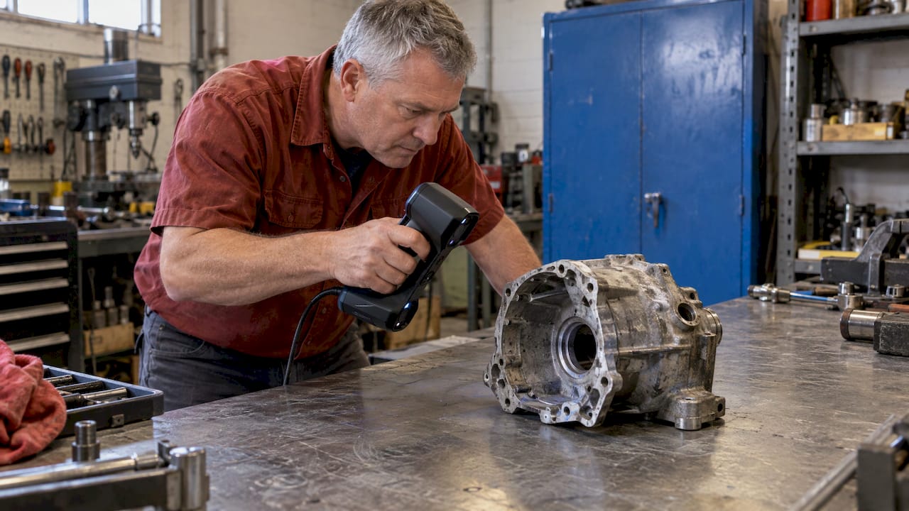
Digitizing a legacy part means capturing a physical component with a 3D scanner, cleaning the scan data, and rebuilding it as an editable CAD model, so you can reproduce, modify, or archive a part that has no drawings or no supplier. For obsolete and undocumented components, this is usually the shortest path from a worn original to a replacement you can fit. The steps below cover the workflow, what limits accuracy, how to verify the model, and what to prepare before you ask for a quote.
TL;DR
- Digitizing a legacy part is a three-stage job: scan the original, clean and align the data, then rebuild it as parametric CAD that you own and can edit.
- Scan accuracy depends on the scanner, but also on surface finish, lighting, temperature, part size and operator technique.
- Verify the CAD model against the scan before you make anything, and verify the printed part against the original before you commit to a batch.
- FDM printing suits low-volume replacement parts because it avoids tooling; typical FDM tolerance is about ±0.2 to 0.5 mm, so mating features need to be designed for it.
- At CC 3D Labs, every production job is quoted individually after a test print of the actual model.
Table of Contents
- What digitizing a legacy part actually involves
- The workflow, step by step
- What limits scan accuracy
- How to check the digital model before you make anything
- Reproducing the part: process and material choices
- What to provide before a digitizing project
- Our perspective
- Get your legacy part digitized
- FAQ
- Sources
What digitizing a legacy part actually involves
A legacy part is a component that is no longer made, no longer documented, or no longer available from anyone who can supply it. Typical cases include a discontinued bracket on a production machine, a trim piece on a restored vehicle, a housing from equipment whose manufacturer closed, or a part whose drawings were lost, never existed, or describe a revision that was later modified in the field.
The Society of Manufacturing Engineers describes 3D scanning of obsolete parts as a non-contact, non-destructive method: the scanner records the surface without touching it, so a fragile or one-of-a-kind original is not put at risk. The result is a dense point cloud that can support design-intent CAD modeling, and it removes the need to buy replacements that may not exist. SME also frames it as insurance against losing essential parts for aging equipment.
Fraunhofer IPK describes the same idea as digital reconstruction: a physical component captured by 3D scanning becomes a precise, editable CAD model, which allows analysis, reproduction, and digital twins even when no design data exists. That distinction matters. A scan alone is a record of one worn example. A CAD model is a design you can correct, scale, tolerance, and reuse.
When digitizing makes sense
Digitizing is worth the effort in these situations:
- The part is obsolete and no aftermarket supplier exists.
- You need more than one copy, or expect to need more later.
- The original is worn or damaged and you need the intended geometry, not the current wear.
- The part must fit or mate with existing components and you want the fit controlled.
- You want a permanent digital record so the part is never lost again.
For a single simple part with two or three measurable dimensions, calipers and a sketch may be faster. Once the geometry includes compound curves, many features, or tight relationships between features, scanning pays for itself.
The workflow, step by step
The same sequence applies whether the part is an automotive trim clip or a machine guard. Our own more detailed write-ups cover the scanning side of legacy part reproduction and the scan-to-CAD workflow.
- Assess and prepare the original. Clean the part, note which surfaces are worn, and decide which features matter for function. Shiny, dark, or transparent surfaces are harder to capture and may need preparation.
- Scan. A handheld scanner records overlapping passes from multiple angles. Complete coverage of the part, including undercuts and internal features that can be reached, prevents holes in the data.
- Clean the data. Fraunhofer IPK’s description of the process includes filtering error points and noise, merging overlapping scans, and optimizing the data before features are segmented and classified.
- Build the CAD model. The cleaned mesh becomes a reference for constructing real solid geometry.
- Verify. Compare the CAD model to the scan, then compare the first physical part to the original.
- Produce. Print, test fit, and then move to a small batch if the part works.
From mesh to editable solid
This is the stage where most of the engineering judgment sits. Autodesk’s scan-to-CAD workflow explains that the mesh is imported into CAD software and serves as a reference. The hardest step is converting the mesh into true solids. For simple parts built from primitives, you model the solid by hand using the mesh as a guide. For complex surfaces and compound curves, cross-sections from the mesh act as templates for spline contours.
A published eight-step process from QUICKSURFACE follows the same logic: import the scan, isolate the relevant part, simplify the mesh, align it to axes and symmetry planes, create reference sections and curves, fit CAD surfaces, convert to solids, validate accuracy with deviation analysis, and export to standard CAD formats.
Two practical points follow from this:
- Design intent beats raw shape. A worn bore is not round, and a worn flat is not flat. The CAD model should represent what the part was meant to be, with a round bore at a nominal diameter and a flat plane, not a copy of the wear. This is why a parametric model is more useful than a converted mesh. More on the conversion step is in our guide to mesh to CAD conversion and our explainer on what scan-to-CAD is.
- Not every feature should be traced. Simple holes, bosses, and pockets are often better redrawn as clean features, with the scan as the position reference.
Pro Tip: Decide before modeling which dimensions are critical (mating faces, hole centers, shaft diameters) and which are cosmetic. Spend the verification effort on the critical ones.
What limits scan accuracy
Our professional handheld 3D scanning is accurate to about 0.1 mm. That figure describes the scanner under good conditions. The result you get on a given part depends on several things at once.
Academic work published in the International Journal of Advanced Manufacturing Technology on noise reduction in handheld scanning groups the influences into three families: environmental factors such as ambient light and temperature gradients, object properties such as reflectivity, color, and texture, and scanner parameters such as configuration, path, and distance. The same source reports that inconsistent illumination introduces random error and that scanning distance affects noise, with one example rising from 30 µm at 585 mm to 80 µm at 1200 mm.
In practice, that translates to:
| Factor | What it does | What helps |
|---|---|---|
| Reflective or dark surfaces | Gaps or noisy data | Surface preparation, adjusted scan settings |
| Lighting changes | Random error | Stable, controlled lighting |
| Temperature swings | Drift in the data | A stable working environment |
| Working distance | More noise farther from the part | Consistent, close scanning passes |
| Part size | Alignment error accumulates | Reference targets, careful registration |
| Wear on the original | Scan is accurate, but of a worn shape | Design-intent modeling |
We cover these in more depth in our guides to achieving a high quality 3D scan for manufacturing and to optimizing 3D scan accuracy.
How to check the digital model before you make anything
Verification happens twice, and skipping either one is how a good scan turns into a bad part.
Stage one: model against scan. Overlay the finished CAD solid on the scan mesh and run a deviation analysis, which produces a color map showing how far each region of the model sits from the scan. The final steps of the QUICKSURFACE process above call for exactly this. Expect deviation where the original was worn, and decide region by region whether the model should follow the wear or the intended geometry.
Stage two: printed part against original. Fit the first printed part to its real mating components. Measure the critical dimensions with calipers or gauges. Where the original is available for comparison, check that the printed part seats, aligns, and moves the way the original did.
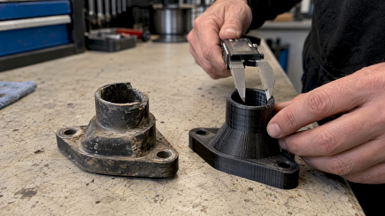
This second stage is why we run a test print on every production job. It tells us how the actual model behaves on the printer before a batch is committed, and it gives you a physical sample to fit. Our article on test printing first for scan-fit replacement parts walks through the process.
Pro Tip: If a feature must fit with a specific mating part, scan that mating part too. Designing the replacement against both surfaces removes guesswork about the clearance.
Reproducing the part: process and material choices
Once the model is verified, the manufacturing method decides cost and risk. NIST’s page on additive manufacturing states that 3D printing changes the economics of low-volume production, including end-of-life and repair parts, by avoiding tooling costs, eliminating inventory and warehousing costs, reducing obsolescence risk, and removing the cost of maintaining older tools. That is the core case for printing legacy parts: you do not build a mold for a part you need eight of, and you do not warehouse spares for equipment that may never need them. The same logic applies to anyone keeping older machinery running, as in this overview of the engine rebuild process.
At CC 3D Labs, replacement parts are produced by FDM printing on a farm of Bambu Lab printers. Material selection follows the working environment of the part:
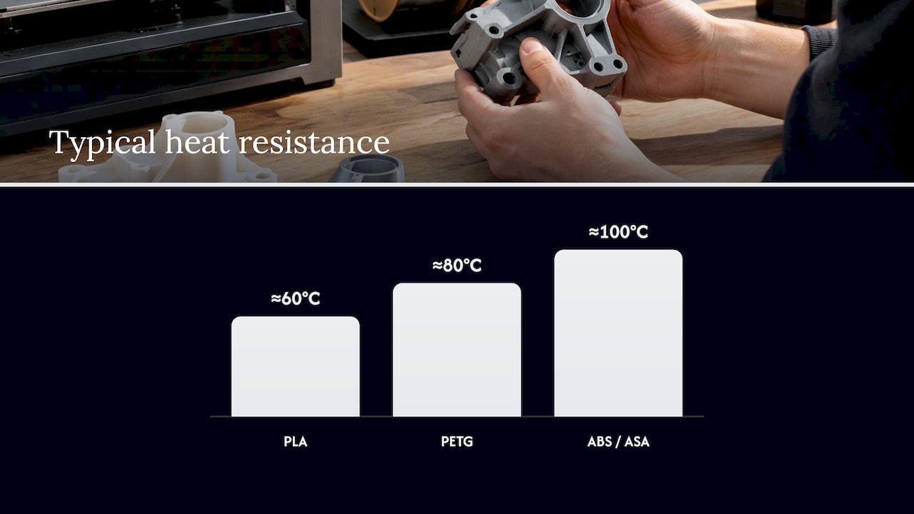
| Material | Typical heat resistance (approx.) | Typical use |
|---|---|---|
| PLA | About 60°C | Fit checks, form models, indoor non-structural parts |
| PETG | About 80°C | Tougher general-purpose parts |
| ABS / ASA | About 100°C | Higher-temperature parts; ASA for outdoor exposure |
| PC | Higher-performance engineering use | Demanding functional parts |
| Carbon-fiber nylon | Engineering-grade stiffness and strength | Structural, load-bearing parts |
These are industry-typical approximations, not guarantees for a specific print, and the right choice depends on load, heat, chemicals, and UV exposure. FDM tolerance is generally about ±0.2 to 0.5 mm, so mating features should be designed with that in mind: clearance on sliding fits, and tested interference for press fits. For parts that will see real service, see our notes on 3D printed end-use parts.
We do not offer metal printing, resin processes, CNC machining, or injection molding. If your part needs one of those, we can still deliver the verified CAD model, which is the portable asset, as well as printed mold masters for workflows that use them.
What to provide before a digitizing project
A clear brief shortens the path to an accurate quote. Gather the following:
- The physical part, or the best available example, plus any mating parts if fit matters.
- Function and load: what the part does, what forces it carries, and what it touches.
- Environment: temperature range, outdoor exposure, oils, fuels, solvents, or cleaners.
- Critical dimensions and features, and any dimension you already know is correct.
- Condition: which areas are worn, broken, or modified, and whether you want original or improved geometry.
- Quantity: one piece, a handful, or a recurring small batch.
- Existing data: any drawings, photos, part numbers, or older CAD, even if incomplete.
- Deliverables: printed parts, CAD files, or both, and the file format your team uses.
Because we quote after a test print of the actual model, there are no fixed prices or blanket turnaround promises. The quote reflects your geometry, material, and quantity. Our guide to getting a quote for a custom 3D print explains what we look at.
Our perspective
Most legacy-part projects fail at the handoff, not at the scan. A clean point cloud is easy to admire, but the part on the shelf has to fit the machine in the shop. That is why we treat scanning, CAD, and printing as one connected job instead of three separate purchases.
We run professional handheld 3D scanning with accuracy to about 0.1 mm, rebuild the geometry as editable CAD, and print on our Bambu Lab FDM farm. Owning each stage lets us catch problems early: a worn surface that should not be copied, a mating feature that needs clearance for FDM tolerances, a material that will not survive the heat near an engine.
We are owner-operated, and we talk to the customer throughout. We take on awkward, fragile, and unusual parts, including ones other shops have turned down, and we test print the actual model before quoting production so the numbers match reality. For automotive shops, restorers, engineers, and small manufacturers who need a dependable supply of a part nobody sells anymore, that is the approach we believe works.
Justin
Get your legacy part digitized
If you have a part that is out of production, undocumented, or too costly to tool, CC 3D Labs can scan it, rebuild it as CAD, and print it in a material suited to the job. We serve the Greater Philadelphia area and Bucks County with residential pickup (we have no walk-in storefront), and completed orders ship anywhere in the United States.
See our scanning, CAD, and printing services, or start with the 3D scanning lab. To request a scan quote, use the 3D scan request form. For printing, use the 3D print quote page, and for CAD-only work, the 3D modeling and CAD quote page.
FAQ
Can you digitize a part that has no drawings at all?
Yes. That is the main use case. The scan captures the physical geometry, and the CAD model is built from it, so the part does not need existing design data. Fraunhofer IPK describes this as reverse engineering that works even without existing design data. Our overview of reverse engineering in 3D covers the basics.
How accurate is the digital model of my part?
Our professional handheld scanning is accurate to about 0.1 mm. The finished CAD model accuracy also depends on surface condition, part size, and how much wear the original has. We verify the model against the scan with deviation analysis, and the printed part is checked against the original.
What materials can the replacement be printed in?
We print FDM in PLA, PETG, ABS, ASA, PC, and carbon-fiber nylon, with multi-color printing available. The right choice depends on heat, load, and exposure. We do not print in metal.
Do you publish prices or turnaround times?
No. Each production job is quoted individually after a test print of the actual model, and we make no blanket turnaround guarantees. Send the part details through the quote form and we will respond with a quote for your specific job.
Sources
- Reverse Engineer Obsolete Parts with 3D Scanning, SME
- Reverse Engineering with 3D Scanning, Fraunhofer IPK
- What is a Scan To CAD Workflow?, Autodesk Fusion Blog
- How to Convert 3D Scan (STL/OBJ) to CAD, QUICKSURFACE
- An industry-oriented workflow for noise reduction in handheld scanning, Queen’s University Belfast
- Additive Manufacturing/3D Printing, NIST