
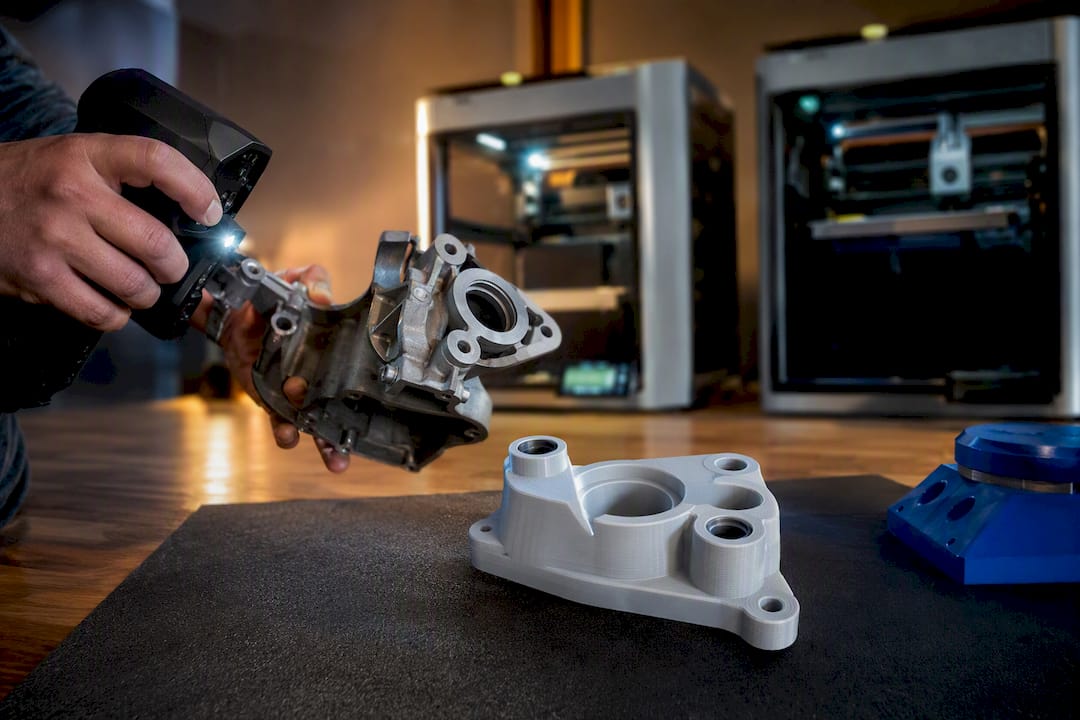
3D-printed replacement parts made from a scan and reverse-engineered CAD file are the fastest practical route for most legacy and low-volume functional spares. That path works reliably for plastic brackets, housings, trim, and small mechanical components, but it depends on correct material selection and real fit-and-function validation, not just a clean scan. CC 3D Labs builds that reliability in through professional high-accuracy 3D scanning and test printing before any final quote.
TL;DR:
- Professional high-accuracy 3D scanning (accuracy within 0.1 mm) ensures the geometric data used for reproducing parts remains precise enough for functional fits and cosmetic details.
- Suitable parts for 3D printing typically include trim, brackets, housings, and prototypes, but the process is not appropriate for load-bearing, high-temperature, or certified components.
- Material choice, such as PETG for impact resistance or ABS for heat resistance, plays a more critical role in part durability than geometric precision alone.
- Validation involves a test print to verify fit and function, with thorough inspection, functional testing, and documentation before final production or installation.
- Accurate reproduction starts with detailed photos, measurements, and a physical sample, with options for professional scanning and reverse-engineering if the part is complex or damaged.
Table of Contents
- When Does 3D Printing Make Sense for Replacement Parts?
- What Does the Scan-to-Print Workflow Look Like?
- Which Materials and Design Rules Actually Matter?
- How Do You Validate a Printed Replacement Part Before Installing It?
- What Should You Send a 3D Printing Service (and What Should You Ask)?
- What We’ve Learned Reproducing Restoration and Small-Batch Parts
- Get a Quote for Your Replacement Part
- Primary Sources and Further Reading
- Sources
- FAQ
When Does 3D Printing Make Sense for Replacement Parts?
Not every broken part belongs on a print bed. The best candidates share a few traits: moderate mechanical load, no exotic certification requirement, and geometry too obsolete or too custom to source off a shelf.
Trim pieces, bezels, clips, brackets, housings, mounting features, jigs, fixtures, and one-off fit-test prototypes all print well and hold up in service. These parts fail gracefully, tolerate the layer lines inherent to FDM, and rarely need anything beyond PLA, PETG, or ABS/ASA to do their job.
The category to avoid is different: critical high-temperature metal load-bearing components, pressure vessels needing certified materials, and anything under a regulatory certification requirement (aerospace hardware, DOT-rated brake components, and similar). FDM plastic isn’t the right tool there, full stop.
Before committing to reproduce obsolete parts this way, run the part through a short mental checklist:
- Function – Is it structural, cosmetic, or somewhere in between?
- Environment – Heat, UV, chemical exposure, or outdoor weathering?
- Tolerance – Does it mate against a precision surface or just clip into place?
- Quantity – One prototype or a small production run of twenty?
- Repairability – Would a failure be a minor inconvenience or a safety issue?
If the answers land on the low-risk side, custom 3D printed parts are usually the quickest and most economical way to get a working replacement in hand.
What Does the Scan-to-Print Workflow Look Like?
Reproducing an obsolete or damaged part is not a single step. It is a short sequence, and skipping any of them is where most reproduction projects go wrong.
- Inspect and document. Photograph the worn or broken part from every angle and record the key measurements by hand. Note where it has degraded versus where it was originally designed.
- Capture the geometry. Professional handheld 3D scanning (accuracy to ~0.1 (mm) handles complex freeform shapes well, portable scanning has become a standard tool in automotive reverse engineering because it captures detail in situ without full disassembly. Photogrammetry suits larger, lower-detail parts, while a CMM earns its place when a datum surface has to be dead accurate.
- Build parametric CAD. Clean and align the raw scan mesh, then reconstruct the part with design intent restored, not its accumulated wear or warp copied over. Reverse-engineering research on rare European car engine components frames this as a function-first process: recover the mating surfaces and interfaces the part was meant to have, then apply FDM-specific adjustments for print orientation, support structure, and wall thickness.
- Print, test, refine, produce. A first-article test print gets checked against the assembly for fit and function, the CAD gets refined based on what that test reveals, and only then does the job move to a small-batch run.
A fog light bezel reconstruction project is a good illustration of step 3 in practice: parametric reconstruction rebuilt the mounting tabs and grille pattern that the physical part had lost to damage, restoring geometry the scan alone couldn’t recover.
Pro Tip: If the part carries a safety-critical datum or an internal feature a handheld scanner can’t see, budget for a CMM or CT pass before finalizing CAD. Skipping that step on the wrong part is how a “quick fix” turns into three redo cycles.
Which Materials and Design Rules Actually Matter?
Material choice, more than geometric precision, decides whether a printed replacement part survives its first season of real use.
- PLA – Fine for low-load, cosmetic, or short-lived parts. Cheap, dimensionally stable, but softens well below typical under-hood temperatures.
- PETG – A strong middle ground: tougher under impact, holds up to outdoor exposure and moisture better than PLA.
- ABS/ASA – Better heat and UV resistance, the usual pick for exterior automotive trim or anything that sits in direct sun.
- PC (polycarbonate) – Higher strength and heat resistance for parts under real mechanical stress.
- Carbon-fiber nylon – The stiffest, most wear-resistant option on this list, at the cost of trickier printability and more aggressive post-processing.
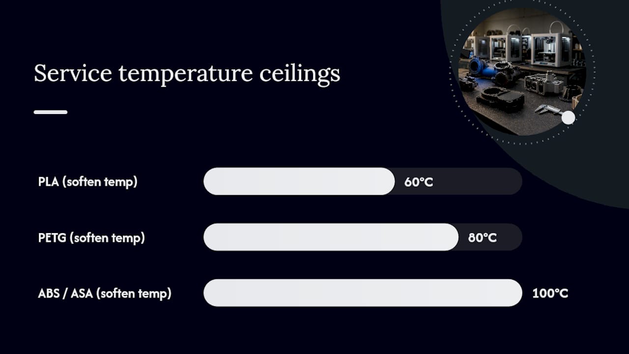
Every FDM material has a rough service ceiling: PLA softens around 60°C, PETG around 80°C, and ABS/ASA around 100°C. A part destined for an engine bay or a sun-baked dashboard needs that ceiling checked against its actual operating temperature, not assumed.
Design rules matter as much as material grade. FDM parts are anisotropic, meaning they’re weaker between layers than along them, so print orientation should follow the load path, not just the easiest support setup. Minimum wall thickness, generous fillets at stress points, reinforcing ribs instead of just thicker walls, and threaded inserts or metal fasteners at load-bearing joints all reduce the odds of a cracked mount six months down the road. One reconstruction case rebuilt thin mounting tabs with a slightly larger engaged surface and local ribs specifically to compensate for FDM’s directional weakness, rather than simply thickening the whole wall. Sealing surfaces, threads, and any mating faces usually need a light sanding or post-machining pass since printed layer lines rarely seal against an O-ring or gasket straight off the bed.
How Do You Validate a Printed Replacement Part Before Installing It?
Skipping validation is the single most common way a promising CAD file turns into a part that doesn’t fit. A first-article print earns its keep here.
Dimensional inspection comes first: compare the printed part against the CAD model and against the critical datums on the actual assembly. A caliper check is enough for most cosmetic or low-load parts; full GD&T inspection is worth the extra step for anything mating against tight tolerances or another manufactured component.
Functional testing follows the same logic. Confirm fit inside the real assembly, run a bench load test if the part carries any mechanical stress, check for leaks or pressure holding where the application calls for it, and cycle moving parts through an accelerated wear test before calling the design final. Practitioner guidance on reproducing obsolete components makes the point plainly: scanning alone isn’t sufficient for functional or safety-relevant parts, and it needs to be paired with material characterization and documented testing.
Ask for a few concrete deliverables before signing off:
- Inspection images or a short report comparing the print to the CAD model
- A deviation map for any features with tight fit requirements
- Written test results for whatever functional check applies to the part
That paper trail is what turns “looks right” into “verified right.”
What Should You Send a 3D Printing Service (and What Should You Ask)?
Getting a usable quote and an accurate part on the first try comes down to what you hand over up front and what you ask in return.
- Send clear photos of the part from multiple angles, including close-ups of any worn, cracked, or missing features.
- Provide reference measurements taken by hand, even rough ones, especially for features a scanner might not resolve cleanly.
- Include the actual sample part whenever possible. A physical part beats photos every time for scan accuracy.
- Note critical interfaces and environmental demands. Say up front if the part sees heat, vibration, chemical exposure, or a tight tolerance fit.
- Attach any assembly drawings you already have, even partial or outdated ones.
On the service side, ask direct questions: Does the shop run a test print before finalizing a quote? What scan accuracy do they actually deliver? What materials and printer platforms do they run? What inspection or validation steps come with the job? And how does shipping or local pickup work?
Pro Tip: A service that quotes a fixed price before ever seeing the part or running a test print is skipping a step that protects you. A test print first means the quote reflects the real job, not a guess.
CC 3D Labs answers all of those the same way every time: professional handheld 3D scanning (accuracy to ~0.1 (mm), a Bambu Lab FDM farm running PLA through carbon-fiber nylon, CAD and reverse-engineering work in house, a test print before any final quote, and residential pickup around Greater Philadelphia and Bucks County with shipping anywhere in the US.
What We’ve Learned Reproducing Restoration and Small-Batch Parts
The biggest mistake we see isn’t a bad scan. It’s copying wear instead of rebuilding design intent, which just reproduces the same failure a few months later. A test print exposes fit problems early, before they cost anyone a wasted production run. Material choice usually decides success more than scan precision does. We work with automotive restorers, engineers, product developers, and small businesses, and the projects that go smoothly are the ones where someone tells us how the part actually gets used.
— Justin
Get a Quote for Your Replacement Part
CC 3D Labs runs the full loop in house: professional handheld 3D scanning (accuracy to ~0.1 mm) to capture a worn or broken part, reverse-engineering CAD to rebuild it around its original design intent, and a Bambu Lab FDM farm printing in PLA, PETG, ABS, ASA, PC, and carbon-fiber nylon.
Every job gets a test print before any final quote goes out. There’s no fixed price list and no blanket turnaround promise, because a bracket and a reconstructed engine housing take genuinely different amounts of work. What you get instead is a quote based on your actual part, not a guess. Local customers in Greater Philadelphia and Bucks County can arrange residential pickup, and finished orders ship anywhere in the US. If you’re ready to move from a broken part to a working reproduction, request a 3D printing quote, start with a 3D scan quote if the part needs to be captured first, or get a CAD reverse-engineering quote if you already have scan data in hand. Our 3D printing services page covers the full range of what we run.
Primary Sources and Further Reading
Readers who want the underlying research behind this workflow can start with the reverse engineering methods study on rare car engine components, the multi-criteria comparison of capture methods for remanufacturing, and the scan-to-CAD production guide from Measurement Solutions. For restoration shops handling classic vehicles, Magic Motorsport’s remap workflow guide offers useful adjacent context.
Sources
- Application of Reverse Engineering Methods for Manufacturing Lost Components of Rare European Car Engines
- A Combined Reverse Engineering and Multi-Criteria Decision-Making Approach for Remanufacturing a Classic Car Part
- Reverse Engineering for Automotive: From 3D Scan to Production-Ready CAD – Measurement Solutions Limited
- Reverse Engineering a Damaged Automotive Fog Light Bezel from 3D Scan
FAQ
How accurate are 3D-printed replacement parts?
FDM parts typically print with good dimensional accuracy, and when the source geometry comes from professional handheld 3D scanning (accuracy to ~0.1 mm), the resulting part matches the original design intent closely enough for most functional and cosmetic applications.
Can 3D printing reproduce obsolete or discontinued parts?
Yes. Scan-to-CAD reverse engineering is one of the most practical ways to reproduce obsolete parts when no OEM replacement or drawing exists, provided the part doesn’t require certified materials or metal strength.
What’s the difference between 3D printing and machining for a replacement part?
FDM printing handles complex geometry and low volumes economically without tooling costs, while machining suits metal parts needing tighter tolerances or higher strength than FDM plastics provide.
How long does it take to get a 3D printed replacement part made?
Timelines vary by part complexity, material, and scan requirements, so CC 3D Labs quotes turnaround individually after reviewing a test print rather than publishing a blanket estimate.
Do I need to send the broken part itself to get it scanned?
Sending the physical sample whenever possible produces the most accurate scan, though clear photos and hand measurements can substitute when the original part is missing or too damaged to capture cleanly.