
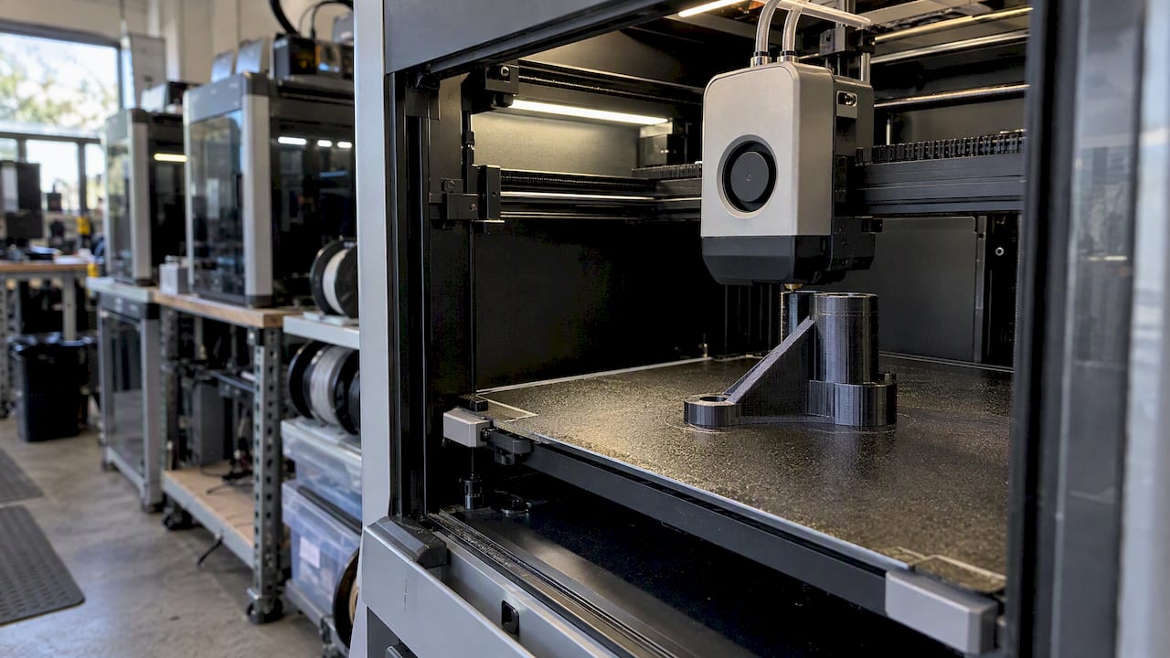
3D printing, and FDM in particular, can reliably produce durable, functional end-use parts for low-volume production, complex geometries, spare parts, and jigs and fixtures, provided the material, process parameters, and testing are matched to the part’s real loads. Success depends on three variables: polymer selection, process control, and qualification testing. As a production partner running a Bambu Lab FDM farm at CC 3D Labs, Justin has watched these three factors separate parts that hold up from parts that fail in the field.
TL;DR:
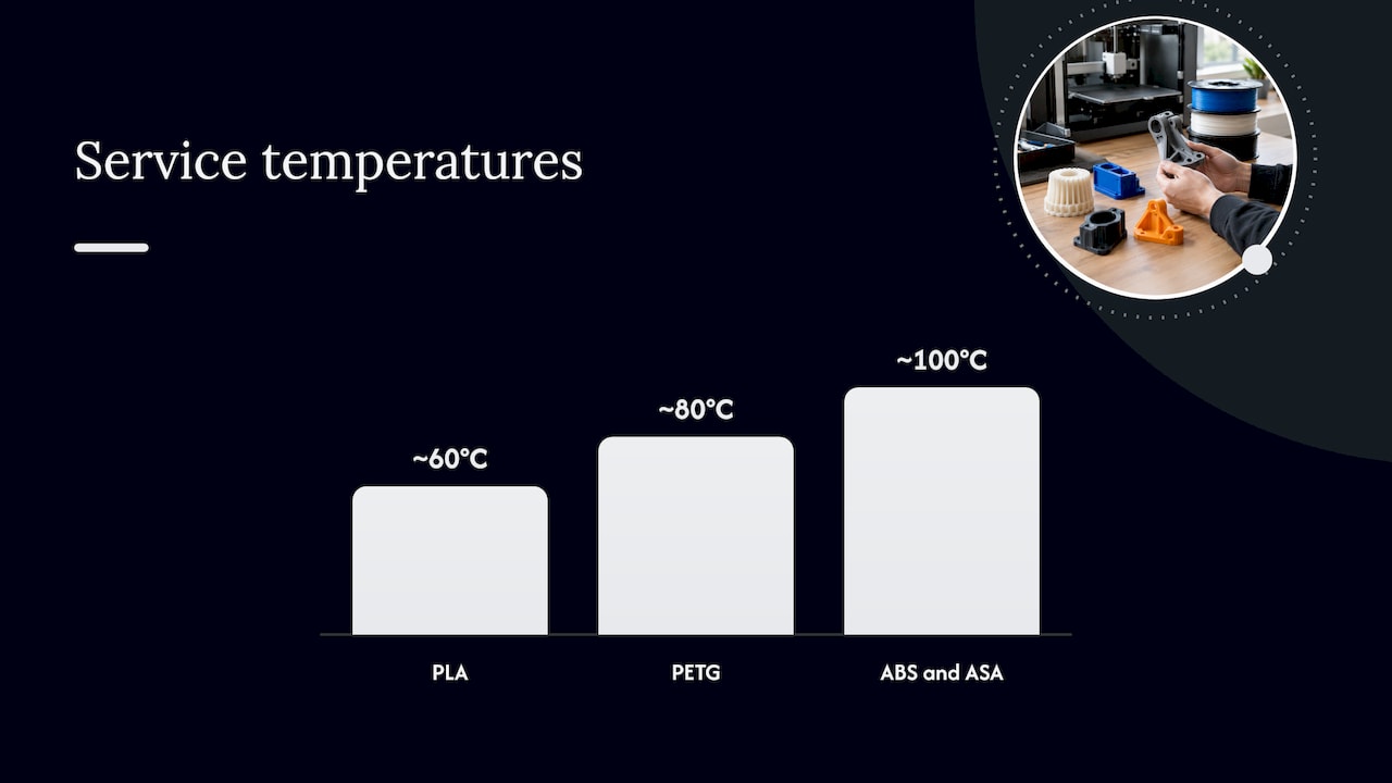
- For outdoor or automotive parts, ASA resists UV better than ABS; both tolerate about 100°C, while PETG suits moderate exposure around 80°C.
- Orient the part so its main load runs parallel to printed layers, then test coupons in that same orientation because cross layer bonds are weakest.
- A material datasheet cannot predict your printer’s results; validate the exact machine, filament lot, and settings with coupons before a pilot batch.
- Use fatigue tests for repeated loading and environmental aging for heat, UV, or chemicals; static strength alone cannot predict service life.
Table of Contents
- Which materials and technologies actually produce end-use parts
- Design and process settings that determine part strength
- How to test and qualify a printed part before it ships
- Post-processing steps that add durability
- Where printed end-use parts fit in a real production plan
- Inside a production-farm workflow for scanning, CAD, and test prints
- Getting from prototype to production without surprises
- Start with a test print before you commit to a production run
- FAQ
- Sources
Which materials and technologies actually produce end-use parts
Additive manufacturing covers several distinct process families, and they are not interchangeable for production work. Material extrusion, commonly known as FDM, builds parts by depositing melted thermoplastic filament layer by layer, and it is the technology we run at our production farm because it scales well for low-volume and small-batch manufacturing in engineering thermoplastics. Other families, such as resin-based photopolymerization or powder bed fusion, serve different jobs entirely, usually where fine surface detail or metal properties matter more than throughput or material cost.
For FDM specifically, material choice drives almost everything about part performance. Each polymer brings a different balance of stiffness, toughness, heat resistance, and chemical resistance:
- PLA prints cleanly and holds tight tolerances, making it suitable for display models, low-stress fixtures, and parts that will not see heat above roughly 60°C.
- PETG adds toughness and moisture resistance over PLA, with a practical service temperature around 80°C, and works well for enclosures, brackets, and outdoor-adjacent parts.
- ABS and ASA tolerate higher heat, around 100°C, and ASA in particular resists UV exposure better than ABS, which makes it a common choice for parts that live outdoors or near a vehicle engine bay.
- Polycarbonate (PC) offers the highest impact strength and heat resistance of the commodity options we print, suited to parts that take repeated mechanical shock.
- Carbon-fiber-reinforced nylon trades some toughness for stiffness and dimensional stability under load, which suits jigs, fixtures, and brackets that need to resist flex.
Feedstock consistency matters as much as the polymer family itself. The UL Blue Card program provides third-party testing of AM feedstock, and frameworks like it exist specifically to reduce variability in how a given filament performs from lot to lot, which matters when a part’s function depends on repeatable mechanical behavior.
Research into next-generation feedstocks shows where commodity polymers are headed. Oak Ridge National Laboratory research on lignin/polymer composites found that engineered formulations can improve tensile strength and resistance to thermal aging in FDM-printed parts, a sign that advanced composite filaments are closing the gap with higher-performance materials. When a part calls for continuous high-temperature service beyond what ABS or ASA can handle, engineering teams typically look to industrial processes built around higher-temperature thermoplastics or metal, which sit outside what a commodity FDM material can deliver.
Design and process settings that determine part strength
FDM parts are inherently anisotropic: they are strongest along the layer lines and weakest across the bond between layers, because the inter-layer interface is where adhesion, rather than polymer continuity, holds the part together. Orienting a part so its primary load runs parallel to the layers, rather than across them, is the single highest-leverage design decision an engineer makes before a file ever reaches the slicer. A review of FDM parts under cyclic loading found that inter-layer delamination remains a common failure mechanism, and that print parameters such as raster angle, infill, and orientation strongly affect both fatigue life and tensile strength.
Several process settings carry outsized influence on mechanical performance:
- Perimeters (wall count) add continuous, strong material around a part’s outer surface, and function-critical parts generally need more than the slicer default.
- Infill density and pattern govern how much internal support a part has against compressive and bending loads, with denser infill trading print time for strength.
- Raster angle changes how the strands within each layer align relative to the load path, and alternating angles between layers helps distribute stress more evenly.
- Layer height affects bond area between layers: thinner layers typically improve inter-layer adhesion at the cost of print time.
- Nozzle and bed temperature control how well each layer fuses to the one below it, and under-extrusion temperature is a frequent, avoidable cause of weak layer bonding.
- Build enclosure reduces drafts and ambient temperature swings that cause warping and uneven layer adhesion, especially relevant for ABS and ASA.
Design-for-additive rules follow directly from these mechanics. Wall thickness should generally be a multiple of nozzle diameter so the slicer can lay down full perimeters without thin, weak gaps. Ribs and gussets reinforce load paths more efficiently than simply thickening a whole section, and fillets at internal corners reduce the stress concentrations that often initiate cracks at sharp edges. Threaded metal inserts, installed with heat, hold up far better under repeated fastening than threads printed directly into plastic. Sharp inside corners, thin unsupported overhangs, and sudden section changes all act as stress raisers and are worth redesigning before they become field failures.
Machine hygiene matters just as much as the design file. Filament that has absorbed moisture prints with visible defects and weaker layer bonds, so dry storage is not optional for anything PETG, nylon, or PC-based. Printers need periodic calibration of extrusion flow, bed leveling, and nozzle condition to hold the tolerances a functional part requires, and we work to a general FDM tolerance of ±0.2 to 0.5 mm on the parts that come off our farm.
Pro Tip: Print your test coupon in the exact orientation planned for the final part. A coupon printed flat on the bed tells you nothing about how the same part will perform standing on edge.
For a deeper look at how these variables interact in practice, our functional parts printing guide for engineers walks through additional parameter trade-offs.
How to test and qualify a printed part before it ships
A manufacturer’s material datasheet describes how a filament performs under controlled, idealized conditions, not how a specific part, printed at a specific orientation with specific settings, will behave in service. NIST’s additive manufacturing part qualification program identifies qualification as one of the major obstacles to using AM parts in high-consequence applications, and recommends either intensive empirical testing or a combined physical-and-digital twin strategy to predict how a part will actually perform.
Practical qualification work usually includes:
- Tensile and flexural testing on coupons printed in the same orientation and settings as the production part, not a generic reference sample.
- Fatigue testing when the part will see repeated loading cycles in service, since static strength alone does not predict how long a part lasts under vibration or flex.
- Environmental aging tests that expose parts to heat, UV, or chemical exposure representative of the real deployment environment.
- A physical twin, a printed sample that mirrors the final part’s geometry, orientation, and process settings, used to validate performance before committing to a production run.
ASME’s work on functional qualification frames this clearly: qualification validates a specific combination of machine, material, and process parameters, not a material in the abstract. A generic datasheet for a given polymer says nothing about whether your specific printer, filament lot, and settings produce a part that performs the same way.
Functional qualification often requires validating a specific machine, material, and parameter combination rather than relying on generic material datasheets.
ASTM F3489 reinforces this by requiring that reported properties for AM polymer parts record the variables that affect them, including material choice, anisotropy, specimen orientation, and test environment, so a logged test campaign should capture all of these before results are trusted. A realistic qualification path runs test coupons first, adjusts orientation or parameters based on failure mode, then moves to a small pilot batch before committing to full production volumes. Our guide to part validation covers how to structure that iteration in more depth.
Post-processing steps that add durability
A part straight off the print bed is rarely the final product for a demanding application. Several post-processing techniques close the gap between as-printed performance and what a function-critical part needs:
- Annealing heats a printed part to just below its polymer’s glass transition temperature, which can reduce inter-layer voids and change strength and ductility. Studies on annealed FDM ABS parts show that loaded annealing variants, where the part is constrained in a mold or fixture during the heat cycle, can control the dimensional shift that unconstrained annealing often causes.
- Surface coatings add abrasion resistance, chemical resistance, or moisture sealing to a porous printed surface, which matters for parts exposed to fuel, solvents, or outdoor weathering.
- Plating or metalizing improves wear resistance and conductivity for select functional needs, though it is chosen less often purely for appearance than for the added surface hardness it brings to a part.
- Bonding and assembly choices, adhesives for permanent joints, fasteners for serviceable connections, or heat-set inserts for threaded hardware, all affect how a multi-part printed assembly holds up under repeated use.
Pro Tip: When annealing a part that must hold a tight tolerance, anneal it inside a mold or jig that constrains its geometry rather than letting it shrink or warp freely in an oven.
Weather-exposed parts carry their own material and finishing considerations, which our guide to outdoor 3D printing materials covers in more detail.
Where printed end-use parts fit in a real production plan
Engineers reach for FDM-printed end-use parts most often in a handful of recurring scenarios, and matching the part to the right scenario avoids wasted qualification effort. Common, realistic applications include replacement parts for discontinued or legacy equipment, custom jigs and fixtures for a specific assembly line, low-volume production runs where tooling costs for other methods would not pay back, and specialized housings or brackets with geometry that would be expensive to machine.
A practical decision path looks like this:
- Define the function and load, including peak force, direction, and whether the load is static, cyclic, or impact-driven.
- Match the environment, checking expected temperature range, chemical exposure, and UV exposure against the candidate material’s known limits.
- Assess regulatory or safety exposure, since a part with no safety consequence needs far less qualification than one tied to a regulated system.
- Weigh cost and lead time against the production volume, since FDM’s advantage shrinks as volumes climb toward what tooling-based methods handle more cheaply per unit.
- Choose the qualification depth, from a simple fit-check print for a low-stakes bracket up to full coupon testing and a pilot batch for a load-bearing part.
A bracket replacing a broken one on a piece of shop equipment might go straight from scan to test print to installed part. A load-bearing fixture used daily on a production line warrants the full coupon-and-pilot-batch path before it goes into service. When volumes grow large or wall sections demand uniform strength that cuts across every layer line, teams often shift toward other manufacturing methods better suited to that scale. For a broader view of what printed parts can realistically cover, see our overview of part classes from prototypes to functional parts.
Inside a production-farm workflow for scanning, CAD, and test prints
Running a Bambu Lab FDM farm day to day means seeing exactly where parts succeed or fail, and that experience shapes how we structure every job. We print in PLA, PETG, ABS, ASA, PC, and carbon-fiber nylon, with multi-color capability for parts that need it, and we pair that with professional handheld 3D scanning accurate to about 0.1 mm for reverse engineering and legacy part reproduction.
Our workflow for an engineer bringing us a functional part typically looks like this:
- Scan or receive CAD, using handheld 3D scanning when a physical reference part exists but no digital file does.
- Test print first, since every job gets quoted individually after we print a test of the actual model rather than from a generic price list.
- Validate fit and function before committing to a batch, catching orientation or tolerance issues on one part instead of a whole run.
- Scale to small-batch production once the test print confirms the design holds up, with printed mold masters available for parts that need a secondary molding step.
We work from Bucks County, Pennsylvania, with residential pickup for local customers and shipping available anywhere in the United States, and we make no blanket turnaround promises since every job’s timeline depends on its own complexity.
Getting from prototype to production without surprises
The engineers who get through qualification fastest are the ones who test function-critical coupons early and iterate on orientation and parameters before committing to a full part. If your application involves cyclic loading or outdoor exposure, plan fatigue and environmental aging tests into the schedule from the start rather than discovering the need for them after a failure. A test-first vendor relationship shortens this process considerably, because every iteration tells you something concrete instead of leaving you to guess from a datasheet.
— Justin
Start with a test print before you commit to a production run
We print functional parts on our Bambu Lab FDM farm and quote every job individually after a test print of your actual design, so you see real performance before committing to volume. Request a 3D printing quote to start that test print, or request a 3D scanning quote if you’re starting from a physical part instead of a file.
Research consistently flags part qualification as a major open challenge for additive-manufactured components in demanding applications, which is exactly why testing your own part before scaling up matters more than trusting a generic spec sheet.
FAQ
Can FDM-printed parts replace machined or molded parts?
For low-volume runs, complex geometries, and parts without extreme continuous heat or precision requirements, FDM can replace machined or molded parts once the design is tested in the intended orientation and load case. For high-volume production or parts needing uniform strength across every axis, teams typically choose tooling-based methods instead.
What makes a 3D printed part weak compared to a molded one?
FDM parts are anisotropic, meaning they are stronger along the printed layers and weaker across the bond between them, so a load applied across layer lines can cause delamination before the polymer itself would fail. Orientation, infill, and temperature settings during printing all affect how close that inter-layer bond comes to the material’s full strength.
Which FDM materials hold up best for outdoor or automotive parts?
ASA generally outperforms ABS outdoors because of its UV resistance, and both tolerate service temperatures around 100°C, while PETG suits moderate exposure around 80°C. Carbon-fiber-reinforced nylon adds stiffness for brackets and fixtures that need to resist flex under vehicle vibration.
How do engineers test whether a printed part is strong enough?
Engineers print test coupons in the same orientation and settings planned for the final part, then run tensile, flexural, or fatigue tests depending on the expected load, following guidance such as ASTM F3489 for recording the variables that affect results. A physical twin, a sample part built to mirror the production geometry, is a common way to validate performance before a pilot run.
Does annealing actually improve a printed part’s strength?
Annealing can improve strength and ductility by reducing inter-layer voids, though it also risks dimensional shift if the part isn’t constrained during the heat cycle. Studies on loaded annealing of FDM ABS parts show that annealing inside a mold or fixture helps control that shrinkage.
Sources
- NIST — Additive Manufacturing part qualification
- ASME — Functional qualification in additive
- UL — Blue Card plastics additive manufacturing
- ORNL — 3D printed lignin/polymer composite with enhanced mechanical and anti-thermal-aging performance