
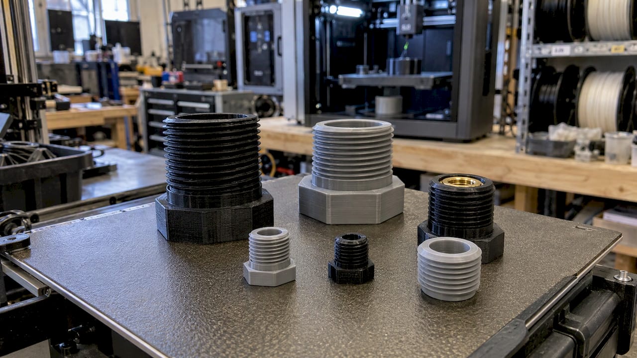
Yes, you can 3D print functional threads, and they hold up when the thread is large enough, the clearance is modeled on the printed side, the axis is oriented correctly, and the load is modest. Below roughly M6 to M8, or wherever a joint is tightened repeatedly or carries real load, a metal threaded insert is the more reliable choice. This guide covers the sizing rules, clearances, print settings, materials and the decision between printed threads and inserts, for engineers and product developers who need parts that assemble the first time.
TL;DR
- Print threads directly only at larger sizes (M8 and up is the comfortable range, M6 the practical floor on a 0.4 mm nozzle). For smaller fasteners or frequent assembly, use a heat-set insert.
- Model clearance on the printed side. FDM threads rarely mate at nominal dimensions, so internal threads are opened up and external threads trimmed, and the values are confirmed on a test coupon.
- Orient the thread axis vertically where you can, use 3 to 5 perimeters, and choose a coarse, plastic-friendly profile such as trapezoidal rather than a sharp 60° V.
- Inserts add measurable strength: in one peer-reviewed test they raised joint capacity by 12% (heat-set) and 40% (Helicoil-type).
- At CC 3D Labs every production job is quoted individually after a test print of the actual model, so threads are checked on your geometry, not a generic sample.
Table of Contents
- Can you 3D print functional threads?
- What decides whether a printed thread works
- Thread profile and design details
- Print settings that protect the thread
- Printed thread or threaded insert?
- Durability, failure modes and safety factors
- What drives the cost of a threaded part
- Our perspective
- Get threaded parts quoted on your geometry
- FAQ
- Sources
Can you 3D print functional threads?
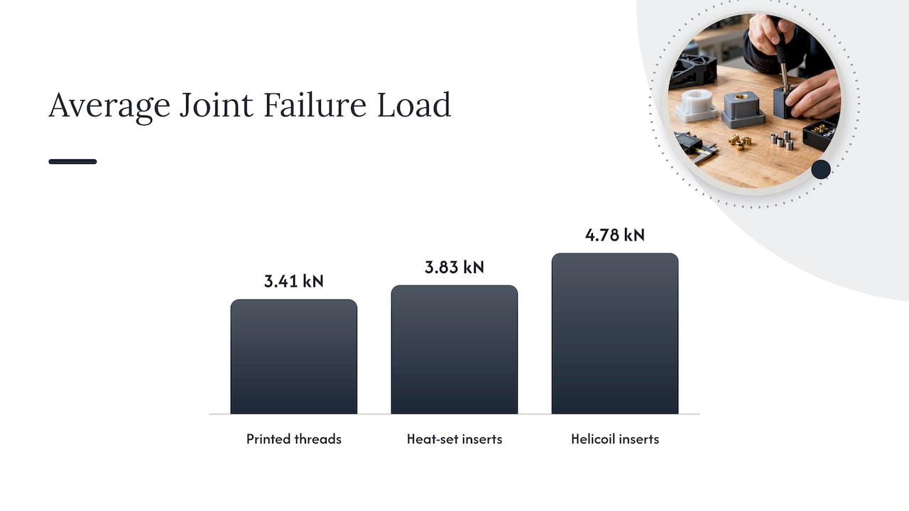
Yes, with limits that are worth understanding before you finalize a design. A 2025 peer-reviewed study tested M8 threaded joints printed in nylon PA12 with a powder-bed process. Directly printed threads failed at an average of 3.41 kN, heat-set inserts raised that by 12% to 3.83 kN, and Helicoil-type inserts raised it by 40% to 4.78 kN. The authors conclude that printed threads suit larger thread sizes and lower mechanical loads, while metal inserts strengthen the joint significantly.
That study used a different print process than FDM, so treat the numbers as a picture of the proportions rather than a rating for any specific FDM part. The pattern still matches what engineers see on layered plastic parts: a printed thread is a capable fastening feature for light-duty and low-cycle use, and an insert is the upgrade when the joint matters.
A separate 2019 comparison of 50 printed M5 test parts found that printed threads performed somewhat worse than tapped holes and brass inserts but still worked surprisingly well. The threads were usually not the part that failed. The surrounding material cracked or delaminated instead, and hole orientation changed how the holes performed. In practice, that means the wall around the thread and the direction of the layers deserve as much attention as the thread geometry itself.
What decides whether a printed thread works
Four things decide the outcome: thread size relative to the nozzle and layer height, clearance, orientation, and the material.
Size versus nozzle and layer height
A thread is a small ridge, and FDM builds it from rounded extrusion lines laid in layers. A 0.4 mm nozzle lays a rounded bead, and the slicer stair-steps the angled flanks of the thread. A fine pitch on a small diameter asks the printer to reproduce features that are close to its own resolution. A coarse pitch on a larger diameter gives each flank several layers to form properly.
A practical rule many designers use: you want at least about five layers across one pitch. With 0.2 mm layers, that points to a pitch of roughly 1 mm or more, and finer layers (0.12 to 0.16 mm) leave more margin. This is a rule of thumb rather than a standard, so confirm it on a coupon in your own material.
Clearance
Nominal CAD dimensions rarely fit. Outside features tend to come out slightly oversized and inside roots tend to close up. For standard FDM printing, common starting points are:
- Internal (nut or tapped-hole) thread modeled about 0.2 to 0.4 mm larger in diameter than nominal.
- External (bolt or stud) thread modeled about 0.1 to 0.2 mm smaller in diameter.
- When both mating parts are printed, split the clearance between them. When one part is a metal bolt or nut, put all of the clearance on the printed part.
- Horizontal thread axes need more clearance than vertical ones because of stair-stepping.
These are averages and starting values, not guarantees. Printer calibration, material, layer height and part size all move the right number, which is why they are confirmed on a coupon before a batch is committed. For context on how much dimensional variation FDM carries, we typically work with ±0.2 to 0.5 mm, and our guide to tolerances in 3D printing explains how to dimension around it.
Apply clearance with CAD offset tools or by changing the thread profile itself, not by scaling the whole part. Non-uniform scaling distorts the 60° flank angle of a standard thread, which concentrates force on the thread tip.
Orientation
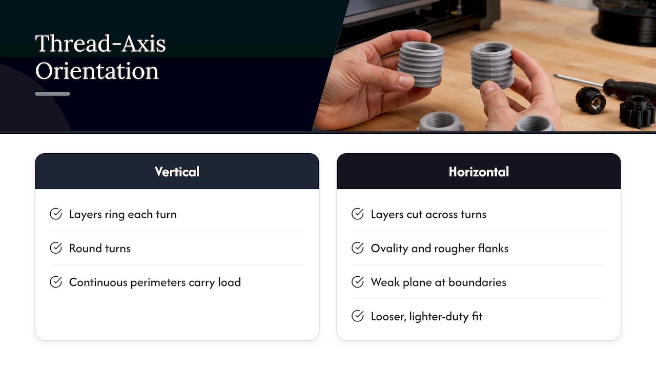
Print the thread axis vertical wherever the part allows. Layers then form a ring around each thread turn, so each turn is round and the load is carried along continuous perimeters. A thread axis lying flat is built from stacked layers that cut across the turns, which produces ovality, rougher flanks and a weak plane at every layer boundary. If the part geometry forces a horizontal thread, increase clearance and expect a looser, lighter-duty fit.
Material
Material choice changes both fit and durability. Typical heat deflection figures, quoted as averages, are about 60°C for PLA, about 80°C for PETG and about 100°C for ABS and ASA. Those numbers matter for threads because a fastener under sustained load creeps as the plastic approaches its softening range.
| Material | Thread behavior in FDM | Typical use |
|---|---|---|
| PLA | Stiff, prints crisp threads, but brittle under torsion and prone to creep under sustained load | Prototypes, fit checks, light-duty caps |
| PETG | Tougher under twisting, slightly rounded crests so it usually needs more clearance | Parts that are turned by hand repeatedly |
| ABS / ASA | Heat resistant to about 100°C; shrinks as it cools, so dimensions need allowance | Enclosures, automotive and outdoor parts |
| PC | High strength and heat performance for demanding assemblies | Functional parts under heavier use |
| Carbon-fiber nylon | Rigid and strong; nylon absorbs moisture, which can shift fit over time | Engineering-grade functional parts |
We print in PLA, PETG, ABS, ASA, PC and carbon-fiber nylon, so the material can be matched to the joint rather than the other way around.
Thread profile and design details
Standard ISO metric and unified threads use a sharp 60° V profile with fine detail at the root and crest. Those sharp edges are hard to form with a rounded 0.4 mm bead. Plastic-friendly designs help in several ways:
- Use a coarse pitch. For custom lids and caps, a pitch of about 2 to 4 mm with two to three full turns is a common starting point. Fewer, bigger turns print more reliably than many small ones.
- Choose a trapezoidal or buttress profile. Trapezoidal (ACME-style) threads with rounded roots and crests tolerate FDM’s rounded geometry better than a sharp V, and a buttress profile suits parts that are loaded in one direction.
- Round the root. A small radius at the base of each thread reduces stress concentration, which is where printed threads begin to crack.
- Chamfer the lead-in. A chamfer on the first half-turn of both the screw and the nut helps the thread start without cross-threading.
- Model the thread as real geometry. Cosmetic threads in CAD, which are only a surface annotation, do not exist in the exported STL file. If the thread is not modeled as solid geometry, the slicer prints a plain cylinder.
Our guides on designing 3D prints for reliable prototypes and parts and on how CAD integration drives printing precision cover the broader modeling habits that thread design depends on.
Print settings that protect the thread
- Layer height: 0.12 to 0.16 mm on a 0.4 mm nozzle gives enough layers across each pitch for clean flanks.
- Perimeters: 3 to 5 walls. Threads are carved out of solid perimeters, so infill density matters far less than wall count in the threaded region.
- Orientation: thread axis vertical, as above.
- Cooling and seam placement: keep the seam away from the thread flank where the part design allows it.
- Supports: avoid supports inside a thread. Design the thread so that it prints without them, which is easier with a chamfered or self-supporting profile. Our guide to support material choices for FDM shows how to plan this.
Start with a coupon: a short threaded sample in the intended material, orientation and layer height. Our article on threaded inserts and test coupons describes how to set one up. A coupon costs a small amount of print time and tells you which clearance value actually mates with your hardware.
Printed thread or threaded insert?
The decision comes down to size, load, cycle count and cost of failure.
| Situation | Better choice |
|---|---|
| Large thread (M8 and up), light load, assembled a few times | Printed thread |
| Lids, caps and jar-style closures with coarse pitch | Printed thread, trapezoidal profile |
| Small screws (M5 and below), or any joint that sees a standard machine screw | Heat-set insert |
| Repeated assembly and disassembly | Heat-set insert |
| Higher clamp load or vibration | Insert, with extra perimeters around it |
| Joint that must be serviced for years | Insert |
A national laboratory’s knowledge base notes that M5 threads are too small to print robustly in plastic. Its worked example is a coupler fitted with brass heat-set inserts: the inserts cost $18 for 40 fittings, under 50 cents each, and they turned a sub-40-cent plastic part into an end-use part that lasted multiple years, with the whole part coming in under $5. For a production run, that is the real cost comparison: a few cents of hardware against the cost of a stripped joint in the field.
Installing heat-set inserts well
Insert performance depends on the hole and the technique. These steps come from published installation guidance:
- Make the hole deeper than the insert. Add roughly 50% to the insert length so displaced plastic has somewhere to go, and size the hole slightly smaller than the insert’s outer diameter, with a chamfer at the entry.
- Raise the perimeter count around the hole. The slicer default of 2 is usually too few. At least 4 perimeters help the insert avoid melting through and reduce sink marks.
- Heat and press straight. Use a soldering iron with an installation tip and press with vertical pressure only, without rotating the insert.
- Seat flush. Press until the insert is about 90% in, then flip the part onto a flat heat-resistant surface and press it flush, letting it cool for a few seconds before loading it.
Iron temperature depends on the plastic, so set it for the material instead of using one value for everything. Going too fast leaves the insert tilted, and going too slow melts too much surrounding plastic and weakens the interface.
Durability, failure modes and safety factors
Printed threads fail in predictable ways, which makes them designable:
- Stripping: thermoplastics are far weaker than steel, so overtightening a printed thread is the most common failure. Specify hand-tight assembly or a torque limit appropriate to the part.
- Cracking around the thread: as the 50-part test showed, the surrounding wall often fails before the thread does. Thicker walls and a vertical thread axis help.
- Creep: a thread under sustained load slowly relaxes. Higher-temperature materials such as ABS, ASA or PC give more margin than PLA.
- Jamming: excess material from printer artifacts has nowhere to go, so the thread binds. Correct clearance and a chamfered lead-in solve most cases.
For PLA specifically, a 2022 study of FDM-printed PLA bolts found a mean compression modulus of about 918 MPa with wide scatter, and about 11% of samples failed in static compression. The authors recommend applying a safety factor when designing PLA threaded connections. Build that margin into the design rather than into the assembly torque.
What drives the cost of a threaded part
The printed thread itself adds almost nothing to material cost. What changes the price of a threaded part is:
- Hardware: inserts are cents each, as the laboratory example above shows.
- Print setup: a vertical orientation, higher wall count or fine layer height changes print time and part count per plate.
- Iteration: a coupon or a fit-check part before the full run adds a small up-front step that prevents a rejected batch.
- Post-processing: insert installation, and any chasing of threads with a tap, is labor.
- Quantity: at small-batch volumes, setup is spread across more parts. See our guide to small-batch FDM production.
Because these variables are specific to each model, we publish no fixed pricing. Each production job is quoted individually after a test print of the actual model.
Our perspective
Most threaded-part problems we see on the design side come from treating a printed thread like a machined one. A machined thread is cut to a standard and inspected against it. A printed thread is built from layers, so its fit depends on the printer, the material, the orientation and the clearance you modeled in, and none of those can be assumed from a drawing.
That is why we start a threaded part with the real geometry and a test print of the actual model, and why we quote each job individually. Our Bambu Lab production farm prints PLA, PETG, ABS, ASA, PC and carbon-fiber nylon, so the material can be chosen for the joint: PETG or ASA for parts that get turned often, a higher-temperature material where heat is a factor.
Our advice to engineers is simple. Print the thread when it is large and the load is light. Specify a metal insert when the fastener is small, the joint is serviced, or the cost of failure is higher than a few cents of hardware. And when the part is a legacy or automotive piece you need to reproduce, scan it first: professional handheld 3D scanning (accuracy to ~0.1 mm) captures the actual thread geometry and mating surfaces, and reverse-engineering CAD turns that into a model you can print with the right clearances.
Justin
Get threaded parts quoted on your geometry
If you are developing a product, restoring a vehicle or planning a small run, we can take the part from drawing or scan to finished, threaded parts. Our Custom 3D Printing, CAD modeling and 3D Scanning Lab services cover the design, the scan of an existing part, and the print in engineering-grade materials. Local customers in the Greater Philadelphia area and Bucks County can use residential pickup (there is no walk-in storefront), and completed orders ship anywhere in the United States.

For a part with threads, send the model or the part itself and tell us the fastener size, the expected load and how often it will be assembled. Our guide to getting a quote for a custom 3D print explains what to include.
FAQ
Is it possible to 3D print threads?
Yes. Larger threads (M8 and up) in a suitable material print reliably when clearance is modeled on the printed side and the thread axis is vertical. Published testing shows printed threads carry load but at lower capacity than threads reinforced with metal inserts, so they suit light-duty and low-cycle joints.
What clearance should I model for a printed thread?
A common FDM starting point is an internal thread about 0.2 to 0.4 mm larger in diameter than nominal and an external thread about 0.1 to 0.2 mm smaller. These are averages, not guarantees. The right value depends on your printer, material, layer height and orientation, so confirm it on a short test coupon.
When should I use a heat-set insert instead of a printed thread?
Use an insert for small fasteners (M5 and below), repeated assembly, vibration, or any joint where failure is costly. Brass inserts cost cents each and are installed with a heated tip. Increase the perimeters around the hole and press the insert in straight, without rotating it.
How do I get a threaded part quoted?
Send us the model, the fastener size, the material you prefer and the quantity. We quote each job individually after a test print of the actual model. Start your 3D print quote; for an existing part that needs scanning, use cc3dlabs.com/3d-scan-quote/, and for CAD work use cc3dlabs.com/3d-modeling-cad-quote/.
Sources
- Load-Bearing Assessment of Threads in 3D-Printed Polymer Joints (PMC, 2025)
- 3D Printing Part Interfaces (Lawrence Berkeley National Laboratory)
- Threaded 3D Printed Part Comparison (Hackaday, 2019)
- Threading 3D Printed Parts: How To Use Heat-Set Inserts (Hackaday, 2019)
- Compression Strength of PLA Bolts Produced via FDM (MDPI Materials, 2022)