
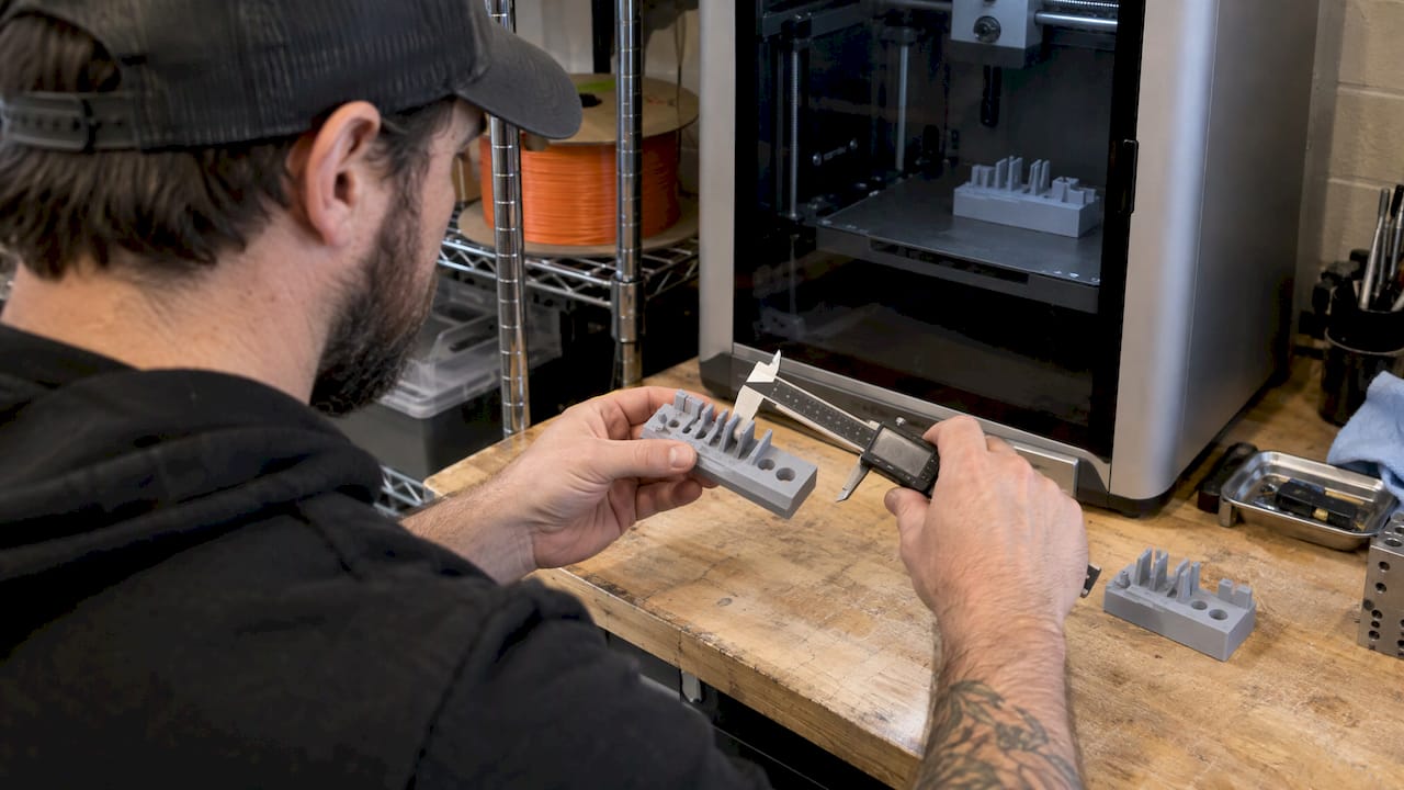
A well-run FDM printer typically holds ±0.2 to 0.5 mm on a finished part, and the gap between the low and high end of that range comes from material, geometry, orientation, calibration and how the part is measured. If you design to that range, specify the critical features up front and have the printed part checked against the model, FDM delivers parts that fit. At CC 3D Labs, every production job is quoted after a test print of the actual model, because accuracy is a property of the specific part and not of the printer’s spec sheet.
This guide is for engineers, product developers, restoration shops and small manufacturers who need parts that assemble, mate and perform, not just parts that look right.
TL;DR
- Plan on ±0.2 to 0.5 mm for typical FDM parts, and design mating features with clearance rather than nominal dimensions.
- Accuracy depends on the part: size, wall layout, orientation, material, layer height and printer calibration all move the result.
- Repeatability across a batch often matters more than a single best-case number, and it is what separates a production run from a one-off.
- Calipers show trends; tight tolerances need optical or CMM (coordinate measuring machine) verification.
- Send critical-fit parts for an individual quote so the dimensions are proven on a test print before the run.
Table of Contents
- Accuracy, precision and repeatability: three different things
- What dimensional accuracy can FDM achieve?
- Where FDM dimensional error comes from
- Which print settings move the numbers
- How calibration closes the gap
- Measuring a print against its CAD model
- Designing fits that work at FDM tolerances
- Material choice affects accuracy and the operating environment
- Batch consistency for small-run production
- Perspective
- Get your part proven before the run
- FAQ
- Sources
Accuracy, precision and repeatability: three different things
The three terms get mixed up in spec sheets, and the difference matters when you write a drawing note.
- Accuracy is how close a printed dimension is to the nominal dimension in your CAD model.
- Precision is how tightly repeated measurements or prints cluster, whether or not they are centered on nominal.
- Repeatability is the ability to produce the same result build after build, across machines, days and batches.
A printer that is consistently 0.15 mm oversize on every hole is precise and inaccurate, and that is the easier problem to fix, because a consistent offset can be compensated in the model or the slicer (the software that turns a model into printer instructions). A printer whose error wanders from part to part cannot be compensated, only controlled.
Stratasys’ own research team makes the same point from the manufacturing side: in a repeatability study of more than 1,200 builds across 16 FDM systems, the company reported dimensional variation within 2% for all systems, materials and geometries, with better than 92% first-time job completion. Those are industrial machines, but the lesson carries over: for production, consistency is the number to ask about.
What dimensional accuracy can FDM achieve?
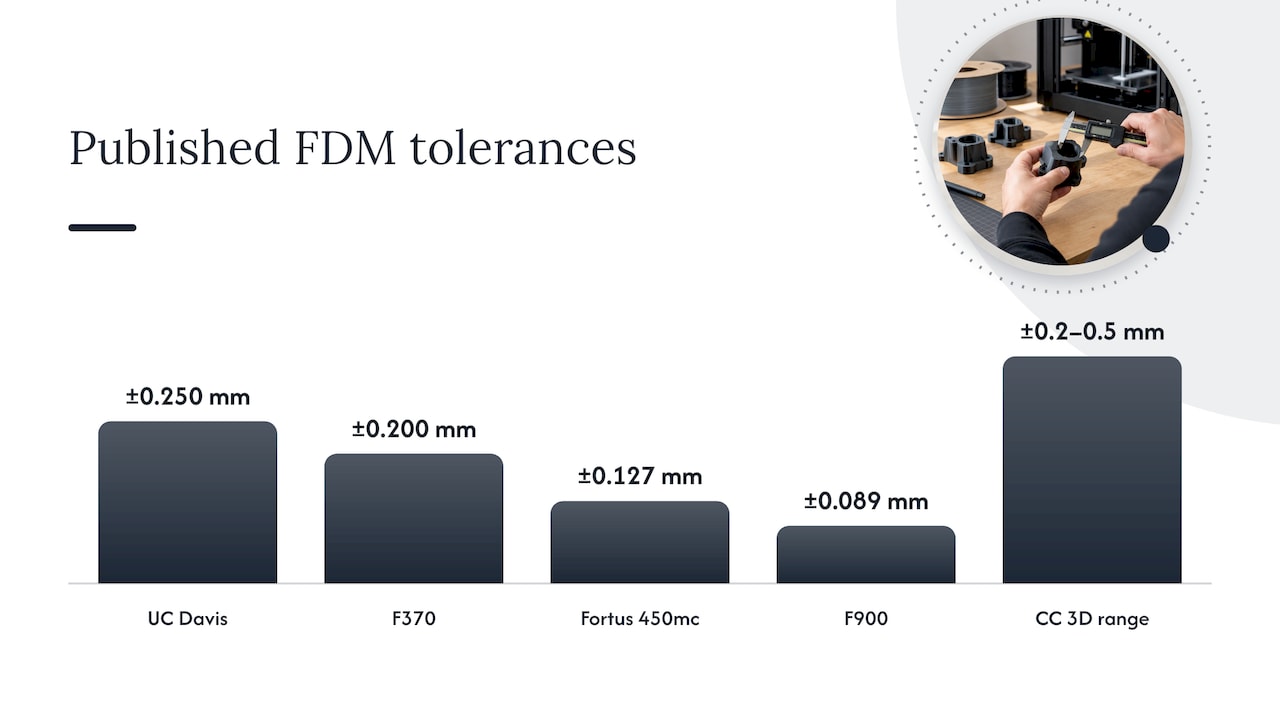
Published figures vary with the machine class, the geometry and who is doing the measuring. The table collects figures from university and manufacturer sources, plus the working range we design to.
| Source | Stated accuracy or tolerance | Notes |
|---|---|---|
| UC Davis FDM systems page | ±0.250 mm tolerance; 0.2 to 0.4 mm overall depending on geometry | Depends on machine calibration and part geometry; 0.2 mm standard layer |
| Stratasys study | ±0.200 mm (F370), ±0.127 mm (Fortus 450mc), ±0.089 mm (F900), or a per-length figure, whichever is greater | Industrial systems |
| UConn Proof of Concept Center | ±0.008 in XY tolerance on an F370 | Published design guidelines, 2020 |
| euspen 2026 conference paper | Baseline desktop FDM of ±0.1 to ±0.3 mm; after iterative calibration, over 95% of parts within the IT7 tolerance grade | 500 PLA rings on a Bambu Lab X1 Carbon, 0.4 mm nozzle, 0.2 mm layers |
| CC 3D Labs working range | ±0.2 to 0.5 mm | Confirmed per part on a test print before production |
Two things stand out. First, the numbers cluster around a quarter of a millimeter, which is the figure to carry into a design review. Second, the euspen result shows what calibration can do: the same class of desktop printer moved from a ±0.1 to ±0.3 mm baseline to tight grades once the process was measured and corrected. IT grades are standard international tolerance grades, and a lower number means a tighter band.
That result was achieved on a single feature type under controlled conditions, so treat it as proof that the process responds to measurement, not as a promise for every geometry. Our own planning range stays at ±0.2 to 0.5 mm until the actual model has been printed and checked.
Where FDM dimensional error comes from
FDM builds a part by laying down beads of melted plastic. Every source of error comes back to how those beads are sized, placed and cooled.
Bead size and the layer stack
The printer cannot print fractions of a bead, so wall thicknesses and feature sizes come out as multiples of the bead width. The UConn guidelines explain that dimensions land slightly above or below the target for this reason. In practice, a 2.3 mm wall on a 0.4 mm nozzle is rounded to what the perimeters can build. Designing walls as whole multiples of the line width removes that rounding.
In Z, the same logic applies to layer height: a feature height snaps to the layer grid. Choose heights that divide evenly by the layer height you plan to print.
Thermal shrink and warp
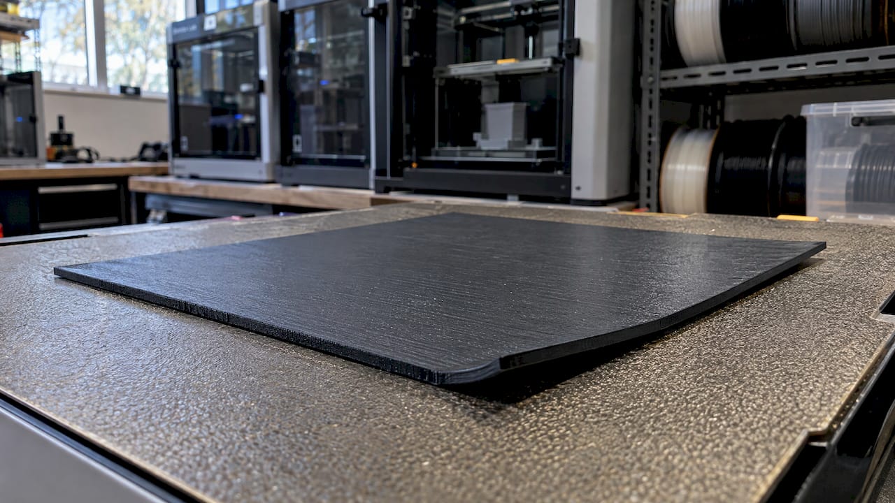
Plastic shrinks as it cools. Larger parts accumulate more of it, and materials with higher print temperatures, such as ABS and ASA, move more than PLA. Shrink is why accuracy is often expressed partly as a percentage of length, as in the Stratasys per-length figures above. Stratasys also notes that low-thermal-expansion materials such as carbon-fiber nylon hold tolerances with less variation than standard thermoplastics, which is one reason we offer carbon-fiber nylon for functional parts alongside PLA, PETG, ABS, ASA and PC.
Holes, first layers and orientation
Holes tend to print slightly undersized, and the first layers can flare outward (often called elephant’s foot). Orientation sets how layers run relative to the part, which affects surface finish and strength per the UConn guidelines, and it changes which axis carries which error: XY accuracy and Z accuracy are not the same number. A bore printed vertically is round differently from a bore printed on its side.
Printer condition
The 5 May 2026 guidance on FDM best practices aside, the practical rule shop floors repeat is to check mechanical looseness (belts, bearings, loose pulleys) before touching slicer settings when accuracy drifts. A settings change cannot fix a mechanical fault, and it can hide one until the next material or size change exposes it.
Which print settings move the numbers
Peer-reviewed work gives a clear picture of the settings with the most leverage, with the caveat that results are specific to the printer and material tested.
- Infill and layer height. A 2022 parametric study of PLA parts found infill density most influential on length and width deviation, while layer height was most significant for angle and height deviation. Its best-performing combination used a 0.1 mm layer height, six perimeters and 20% infill.
- Nozzle temperature. A 2025 comparison of two printers explains that higher nozzle temperatures lower PLA viscosity and give more continuous deposition, while excessive heat causes oozing and surface irregularities that increase width errors. A 2023 framework paper calls nozzle temperature arguably the most crucial setting to fine-tune, with typical ranges of 180 to 230 °C for PLA, 210 to 250 °C for ABS and 210 to 240 °C for PETG.
- Speed and hardware. The same 2025 study found that the best speed, temperature and layer height differed between its two printers, which shows that a settings recipe does not transfer cleanly from one machine to another.
- Thinner layers. A 2023 review of material extrusion process design reports that thinner layers generally improve dimensional accuracy.
Pro Tip: Thin layers help accuracy in Z but raise print time on every part. For a production run, we weigh the tolerance you need against the build time it costs, rather than defaulting to the finest layer.
How calibration closes the gap
The euspen study is the clearest recent example of calibration as a process. The authors printed 500 PLA test rings on a Bambu Lab X1 Carbon, measured them with digital calipers and a CMM, and applied corrections in rounds: reduced horizontal expansion of 0.05 mm per side, a global XY scale factor of about +0.09%, a Z-axis recalibration of about −1% and 2 to 3% extrusion compensation for specific features. Their conclusion was that iterative calibration was essential, because simple offsets improved bias but had to be combined with scaling and feature compensation.
The workflow behind that is useful for any shop:
- Print a calibration part that contains the feature types you care about: bores, bosses, slots, thin walls.
- Measure the result against the model, feature by feature.
- Separate the consistent bias (compensate it) from the scatter (investigate it).
- Apply the correction, reprint and measure again.
- Lock the settings for that material and printer, and re-verify when you change either.
This is the logic behind our test-print-first quoting. Rather than quote a guess, we print your actual model, look at how it came out, and quote the job from there. Our guide to ensuring 3D print accuracy walks through the same sequence in more detail.
Measuring a print against its CAD model
The measuring tool needs to be better than the tolerance you are verifying.
- Digital calipers are quick and fine for spotting trends and checking lengths and outside diameters. The euspen authors found calipers useful for trends, but concluded that CMM or optical metrology is required for final validation of tight tolerances.
- CMM or optical measurement is what you use for a tight-tolerance acceptance decision.
- Handheld 3D scanning compares the whole surface to the CAD model at once and shows warp and distortion that point measurements miss. We provide professional handheld 3D scanning with accuracy to about 0.1 mm, which suits checking a printed part, a mating casting or a legacy component you need to reproduce.
Whichever tool you use, fix the datums (the reference surfaces you measure from) before measuring, and let parts reach room temperature first. Measuring a warm part against a cold model is a common source of confusing readings.
For automotive and restoration work, the scan is often the starting point rather than the check. A scanned original becomes a CAD model, the model becomes a printed part, and the printed part is checked against the scan. Our scanning guide for design accuracy and the steps for scanning objects for printing cover that loop.
Designing fits that work at FDM tolerances
The most reliable way to get parts that assemble is to design clearance in, not to demand a tolerance the process does not hold. Typical starting points:
- Clearance fits (a shaft that must turn or slide) need a gap. The UConn guidelines list a minimum safe clearance between surfaces of 0.020 in and an absolute minimum of 0.007 in for an industrial FDM system. On a desktop-class farm, plan toward the larger end.
- Snug or press fits are best proven with a printed test coupon in the real material before committing to the run.
- Holes should be modeled with a small allowance, since they print undersized, and critical bores can be finished by reaming after printing.
- Walls work best when they are multiples of the line width, and thin features need to clear the process minimum: the UConn guidelines give a minimum safe wall of 0.125 in for their system.
For reference on how mating holes and pins are specified in other processes, this dowel pin hole tolerance reference is a good companion when you are deciding whether a feature should be a press fit or a slip fit, since the fit category you pick drives the gap you model into the printed part.
Our engineering articles go deeper on the standards behind these choices: print tolerance standards explained, what tolerances mean in 3D printing and the benefits of design for manufacturability. If your model needs rework to hit a fit, our 3D modeling and CAD service handles that, including scan-to-CAD for parts without drawings.
Material choice affects accuracy and the operating environment
Material decides both how the part dimensions behave during printing and what the part tolerates in use. A part that holds its dimensions on the bench but softens in a hot engine bay has failed just as surely.
| Material | Approximate heat resistance | Where it fits |
|---|---|---|
| PLA | About 60 °C | Fit-check prototypes, indoor fixtures |
| PETG | About 80 °C | Functional parts with some heat and toughness needs |
| ABS / ASA | About 100 °C | Higher-temperature and outdoor-exposed parts (ASA) |
| PC, carbon-fiber nylon | Per material grade | Demanding functional parts where stiffness and stability matter |
These are approximate working figures, not guarantees for a specific part, and the right material is settled when the job is quoted. If your part lives near an engine, a heater or a window in summer, tell us the environment before choosing PLA.
Batch consistency for small-run production
A single accurate part is a prototype. Fifty parts that all fit is a product. That is the repeatability point from the Stratasys study applied to your project. For a small-batch run, the useful questions are whether the same settings, material lot and orientation are held across the run, and how parts are checked as they come off the plate. Locking the process after the test print is what makes the tenth part match the first. Our guides on why print accuracy matters for prototyping and validating 3D designs lay out the checkpoints.
Perspective
Most accuracy problems we see on a drawing review are not printer problems. They are specification problems: a tight number on a feature that does not need it, no clearance on a feature that does, or no note on which surfaces matter.
We run a production farm of Bambu Lab FDM printers and we work to ±0.2 to 0.5 mm. We would rather tell you that up front and then prove the part on a test print than promise a figure the geometry has not earned. That is why every job is quoted individually after printing your actual model.
Pair that with professional handheld scanning to about 0.1 mm and CAD that corrects the model, and the loop closes: scan the original, model it, print it, check it against the scan. That is how automotive shops and engineers get parts that fit the first time.
Justin
Get your part proven before the run
CC 3D Labs is a 3D printing and 3D scanning service in the Greater Philadelphia area (Bucks County, PA). We print prototypes, functional parts and small batches in PLA, PETG, ABS, ASA, PC and carbon-fiber nylon, and we scan, reverse engineer and model parts that have no drawings. Local customers can use residential pickup (there is no walk-in storefront), and finished orders ship anywhere in the United States.
Send us the model and the features that have to fit, and we will quote from a test print. Start with the 3D print quote form, the 3D scan quote form or the CAD modeling quote form. If you are unsure what to include, our guide to getting a quote lists it, and the services overview shows everything we offer.
FAQ
How precise are FDM printers?
Typical FDM parts hold about ±0.2 to 0.5 mm. University sources describe tolerances around ±0.25 mm for industrial machines, and calibrated desktop printers have reached much tighter grades on simple test features in published studies. Precision depends on the part and the calibration, so critical dimensions are best confirmed on a test print.
How much tolerance should I allow for FDM prints?
Design mating features with a clearance gap instead of nominal dimensions, and start from a gap in the range of a few tenths of a millimeter for parts that must move. Industrial guidance lists a minimum safe clearance of 0.020 in between surfaces. Confirm the final gap on a printed coupon in the actual material.
What affects FDM dimensional accuracy the most?
Material, part size, orientation, layer height, nozzle temperature and printer calibration all matter. Studies on PLA point to infill density and layer height as strong influences on specific deviations, and to nozzle temperature as a key setting. Mechanical condition of the printer underlies all of them.
How do I measure a print against its CAD model?
Use calipers for quick checks and trends, and a CMM or optical measurement for tight-tolerance acceptance. A handheld 3D scan compared with the CAD model shows deviation across the whole surface. Set your datums before measuring and let the part cool to room temperature.
Can you check or reproduce a part that has no drawings?
Yes. We scan the part with professional handheld 3D scanning (accuracy to about 0.1 mm), build the CAD model from the scan and print it, quoting each job individually. Use the scan quote form to describe the part.
Sources
- Stratasys: Repeatability and Performance of Stratasys Fused Deposition Modeling
- UC Davis: FDM Systems
- euspen ICE26126: iterative calibration of FDM parts
- UConn Proof of Concept Center: FDM 3D printing guidelines
- PMC: Parametric investigation of PLA FDM dimensional accuracy (2022)
- PMC: Comparative analysis of dimensional accuracy in PLA-based printing (2025)
- Polymers: A framework for fused filament fabrication (2023)
- PMC: Process design and parameters interaction in material extrusion (2023)
- Dowel pin hole tolerances reference