
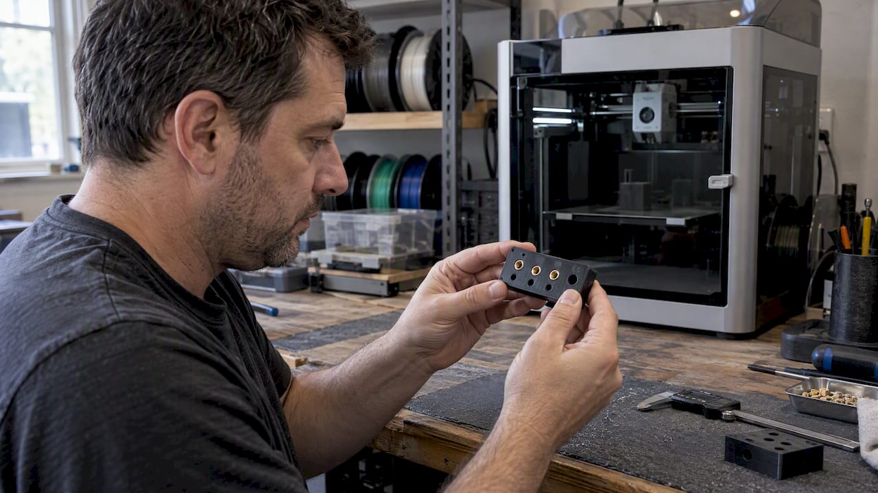
Heat-set brass inserts are the standard solution for durable, reusable screw threads in FDM parts, outperforming printed threads for any component that gets assembled and disassembled more than once. A quick test print confirms the fit before a full production run.
TL;DR:
- Make the hole two thread pitches deeper than the insert, size the boss at about 1.5 to 2 times its knurl diameter, and use over 50% infill.
- FDM printers can vary by ±0.2 to 0.5 mm, so print a coupon with three or four hole sizes and adjust the CAD diameter in 0.05 mm increments.
- Start around 225°C for PLA, 245°C for PETG, and 265°C for ABS; seat inserts to 90% depth while hot, then finish flush with a cold tool.
- Use press in inserts for thermosets, SLA parts, or heat sensitive assemblies; a handheld iron suits prototypes, while a press improves consistency across production runs.
- Before production, inspect sample inserts for flush, square seating and run hand torque and pullout tests; revise the hole or boss if either fails.
Table of Contents
- What threaded inserts are and why they beat printed threads
- Design rules: hole diameter, hole depth, boss geometry, and infill
- Installing heat-set inserts: tools, temperatures, and technique
- How material and printer tolerance change hole sizing
- Testing, verification, and common failure modes
- Using 3D scanning to verify insert fit and alignment
- CC 3D Labs practitioner notes on printing parts for inserts
- When inserts make sense versus other fastening options
- Get threaded inserts installed right on your next print run
- FAQ
- Sources
What threaded inserts are and why they beat printed threads
A threaded insert is a metal sleeve, usually brass, pressed or melted into a printed hole to create a durable mechanical thread that plastic alone cannot sustain through repeated tightening. Printed threads work for low-cycle, low-torque fasteners, but the layer lines that form the thread crest shear and strip after a handful of insertions. Inserts solve that by putting a real metal thread into the plastic, so the fastener load transfers into the insert’s knurls and barbs rather than into printed layers.
Three insert families cover most 3D printing use cases:
- Heat-set inserts: melted into a printed hole with a heated tool, the default choice for FDM thermoplastics.
- Press-in inserts: pushed in cold, better suited to thermoset resins or SLA parts where heat isn’t practical.
- Self-tapping and expansion-style inserts: driven or expanded mechanically, useful for thin walls or assemblies where heat near sensitive components isn’t an option.
Designers most often reach for M3, M4, and M5 metric sizes, or #6, #8, #10, and 1/4-20 in imperial hardware, depending on the fastener already specified for the assembly.
Design rules: hole diameter, hole depth, boss geometry, and infill
Hole sizing should start from the insert manufacturer’s datasheet, then get confirmed with a printed test coupon, since nozzle diameter, first-layer squish, and “elephant’s foot” all shrink the effective hole size on a real part. An undersized hole lets excess plastic flow into the insert’s knurl pattern during installation, which can crack the boss instead of bonding cleanly around it.
- Set hole depth deeper than the insert. SPIROL’s design guidance recommends a hole roughly two thread pitches deeper than the insert itself, so molten plastic has somewhere to displace instead of backing up against the tool.
- Size the boss around the knurl, not the bore. Design guidance from MeDesignLab targets a boss diameter of about 1.5 to 2 times the insert’s knurl diameter, with enough wall loops around the hole to avoid a boss that is mostly infill.
- Raise infill and tighten layer height near the insert. The same guidance points to infill above 50% and a layer height around 0.16 to 0.2 mm, which improves interlayer bonding right where pull-out load concentrates. Our infill breakdown covers how density choices change strength elsewhere in a part.
- Dial in tolerance with small steps. Adjust the CAD hole diameter in 0.05 mm increments between test prints rather than guessing at a single “correct” number, since every printer and material pairs slightly differently with a given insert.
Pro Tip: Print a small test plate with three or four hole diameters side by side so you only need one build to find the tightest fit that still seats the insert flush.
Our broader design guide for reliable prints walks through boss and wall-thickness decisions that pair directly with this sizing approach.
Installing heat-set inserts: tools, temperatures, and technique
An adjustable soldering iron with a dedicated installation tip handles most one-off and prototype jobs, while a heat-set press earns its cost once you’re installing the same insert across dozens or hundreds of parts, since it holds temperature and perpendicularity more consistently than a handheld tip. Ultrasonic welding tools exist for high-volume production but are rarely justified outside dedicated manufacturing lines.
- Installation temperature runs about 10 to 20°C above the part’s print temperature, with CNC Kitchen’s testing citing roughly 225°C for PLA, 245°C for PETG, and 265°C for ABS as practical starting points.
- Preheat the tip, lower the insert into the hole, and melt it to about 90% of its final depth before switching to a cold flat tool or press to seat the final stretch flush, a sequence MATRIX Lab’s testing found keeps the insert from creeping back out as the plastic cools.
- Hold the part steady until the plastic around the insert has solidified, since movement during cooling is what causes a tilted or proud insert.
Overheating the tip risks decomposing the surrounding plastic, while too little heat leaves the knurls only partially embedded and cuts pull-out resistance. Larger inserts carry more thermal mass and need a thicker contact tip or a press to transfer enough heat without lingering too long on one spot.
How material and printer tolerance change hole sizing
Every thermoplastic reacts differently to the same installation temperature, and filler content changes both the hole size and the heat needed to install cleanly.
- A material’s thermal behavior sets your installation ceiling: push too hot and you risk degrading the polymer right at the insert interface.
- Standard FDM printers hold roughly ±0.2 to 0.5 mm dimensional tolerance, which is wide enough to turn a nominal hole diameter into an unreliable fit without a printed test coupon to verify it.
- Glass or carbon-fiber filled filaments, including carbon-fiber nylon, tend to need a slightly larger pilot hole since the filler stiffens the matrix and resists the plastic flow that normally fills insert knurls.
- Parts facing vibration or repeated torque benefit from bumping infill or adding wall loops around the boss rather than relying on insert geometry alone.
- Thermoset resins, SLA parts, or assemblies where heat near electronics is a concern call for press-in inserts or structural adhesive instead of a heat-set approach.
Our comparison of PLA, PETG, and ABS for durable parts goes deeper into how these materials behave under heat and load.
Testing, verification, and common failure modes
A pull-out test and a simple hand-torque check on a sample part catch most problems before they reach production. After installation, inspect each insert for flushness, perpendicular seating, burrs on the exposed thread, and any plastic that squeezed through to the back side of the boss.
- Hole too large: insert sits loose or spins in place, so tighten the pilot diameter in the next test print.
- Boss too thin: cracking around the insert under load means increasing boss diameter or wall loops.
- Tilted insert: uneven pressure during installation; switch to a guided install tip or press for squarer seating.
- Degraded plastic smell or discoloration: a sign of overheating; drop the install temperature and recheck dwell time.
Treat the first few parts as specimens: install, test, and adjust hole diameter or boss design before committing to a full run.
Using 3D scanning to verify insert fit and alignment
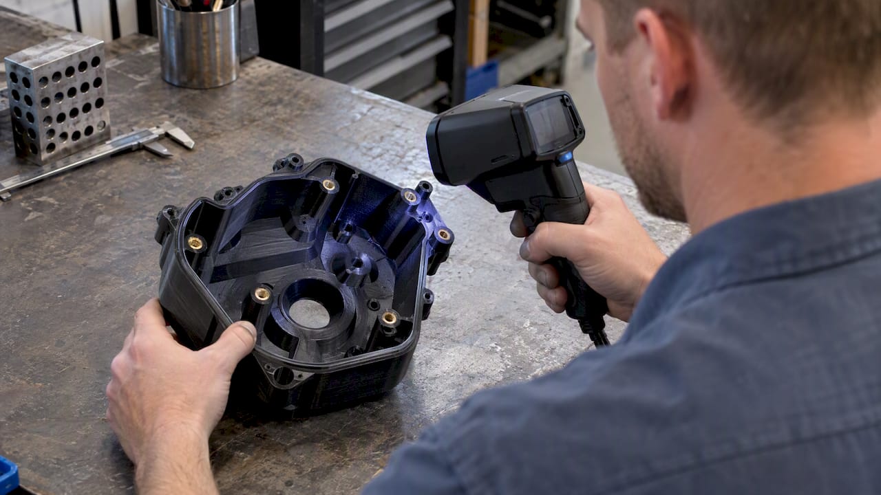
Dimensional inspection after installation matters as much as the installation itself, particularly on parts with multiple inserts that all need to sit flush and square to the mating surface. A partner guide on using 3D scanning for mechanical part inspection outlines how scan-based QA workflows catch tilt and out-of-tolerance bosses that a caliper check alone can miss, which is a useful reference when you’re setting up a repeatable inspection step for insert-heavy assemblies.
CC 3D Labs practitioner notes on printing parts for inserts
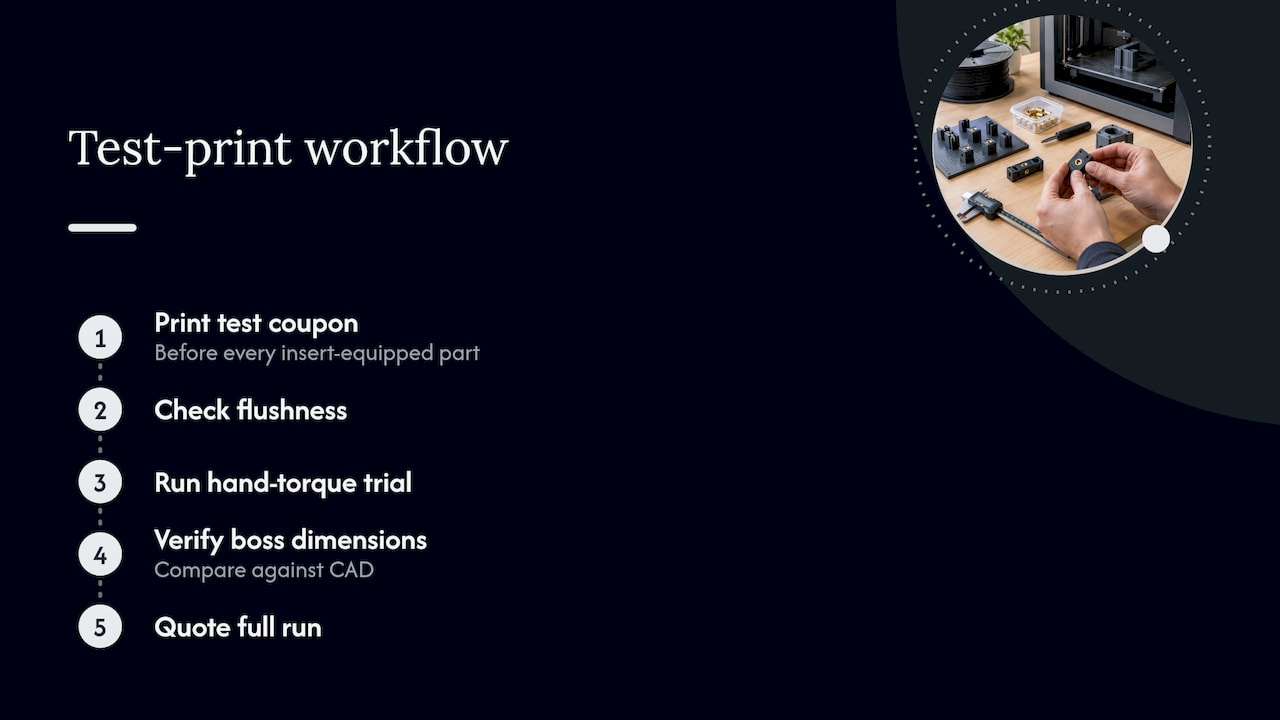
We use FDM printing across various thermoplastic materials, and those materials shape how we size holes and set installation parameters for each job. Every part with threaded inserts goes through a test print first, since hole fit depends on the specific material, nozzle, and geometry combination rather than a single universal number. On the test coupon, we check flushness, run a hand-torque trial, and verify boss dimensions against the CAD model before quoting the full run, and we recommend a heat-set press rather than a handheld iron for larger quantities. Our test-print workflow explains why that step comes before production rather than after.
When inserts make sense versus other fastening options
Threaded inserts earn their place in parts that get assembled and disassembled repeatedly, repaired in the field, or loaded well beyond what printed threads can hold, and the metal thread is what makes that durability possible. The trade-off is real: inserts add material cost, demand careful temperature control during installation, and often justify a dedicated press once volume climbs past prototype quantities. For a one-off bracket, a soldering iron and a steady hand are enough; for a production run, handing the job to a vendor with a repeatable install process protects against the tilt and inconsistency that creep in across dozens of manual installations.
— Justin
Get threaded inserts installed right on your next print run
We print on a Bambu Lab fleet across PLA, PETG, ABS, ASA, PC, and carbon-fiber nylon, and we build every insert job around a test print so hole fit and installation temperature are confirmed before we commit to your full quantity. Beyond printing, we offer professional handheld 3D scanning (accuracy to around 0.1 mm) for reverse-engineering a mating part’s geometry, plus CAD support when you need the boss and hole redesigned around a specific insert.
| What you need | How we help |
|---|---|
| Hole and boss sizing confirmed before production | Test print and dimensional check against your CAD |
| Insert installed flush and square | Press or guided tool installation, torque-checked |
| Reverse-engineered mating geometry | Professional handheld 3D scanning service |
Our services page covers the full range, and every job starts the same way: send your part, and we’ll quote it after a test print confirms the fit. Ready to move forward? Request your test print and quote.
FAQ
How to make 3D printed threads work?
Printed threads can hold light, infrequent fasteners if you size the pilot hole generously and keep torque low, but they strip quickly under repeated use. For anything assembled more than a few times, a heat-set insert in a properly sized hole gives a far more durable thread than plastic alone.
Can I drink out of a PETG cup?
PETG is food-contact safe as a raw material, but a 3D printed cup has layer lines and surface porosity that can trap bacteria and residue, making it harder to clean thoroughly between uses. Most printed PETG parts are better suited to functional or display use than direct, repeated food or drink contact.
What is the best threaded insert for plastic?
For FDM thermoplastics like PLA, PETG, ABS, and ASA, heat-set brass inserts are the standard choice because they melt into the hole and bond directly with the surrounding plastic. Press-in inserts work better for thermosets or SLA resins where heat-set installation isn’t practical.
What are 3D printer seams?
A seam is the visible line where each printed layer’s outer perimeter starts and stops, since the nozzle has to begin and end that loop somewhere. Seams are mostly cosmetic but can be minimized by aligning seam placement to a hidden edge or using a slicer’s randomized seam setting.
Sources
- Tips & Tricks for Heat-Set Inserts used in 3D printing | CNC Kitchen
- How to design the proper hole for heat / ultrasonic inserts (SPIROL white paper)
- Heat set inserts guide – MATRIX lab
- Heat-set insert design guidance (MeDesignLab / university resource)