
TL;DR:
- Most engineers wrongly believe that filling 3D prints at 80% or 100% infill yields the strongest parts, but higher densities often lead to material waste without proportional strength gains. Structural integrity depends more on shell design and perimeter walls than infill density, with optimal performance usually achieved at 20-40% infill for most applications. Selecting appropriate patterns like gyroid and fine-tuning layer overlap and bonding are crucial for producing durable, cost-effective parts efficiently.
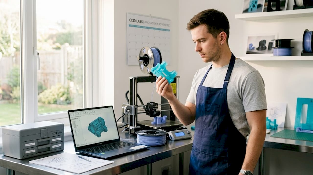
Most engineers assume that cranking infill density to 80% or 100% automatically produces the strongest possible 3D printed part. That’s one of the most persistent and costly misconceptions in additive manufacturing. The reality is more nuanced, and understanding it can save you material, time, and money while producing parts that actually perform better. This article covers what infill is, how density and pattern selection affect mechanical performance, and how to apply a practical workflow when printing functional prototypes or production components.
Table of Contents
- What is 3D print infill?
- Infill density vs. strength: Finding the optimal balance
- Selecting the right infill pattern
- Practical infill selection: Workflow for prototypes and functional parts
- Why optimal infill starts with smart shell design
- Enhance your prototypes with expert infill and 3D printing services
- Frequently asked questions
Key Takeaways
| Point | Details |
|---|---|
| Infill basics | Infill is the internal lattice structure that impacts strength, weight, material use, and print time. |
| Optimal density range | Moderate densities (20–40%) typically deliver good strength-to-weight for prototypes and parts. |
| Wall thickness first | Boosting perimeter walls often delivers more structural strength than increasing infill density alone. |
| Pattern selection matters | Infill pattern choice affects mechanical properties and is based on part load requirements, not just aesthetics. |
| Iterative workflow | Test and adjust infill settings, starting with pattern and shells, to optimize strength and efficiency for each project. |
What is 3D print infill?
Before getting into optimization, you need a precise understanding of what infill actually does inside a part.
3D print infill is the internal lattice or pattern printed inside a part between the outer walls (perimeters) and any solid top and bottom layers. Think of it as the structural skeleton hidden beneath the surface of your printed part. Without infill, most parts would be hollow shells prone to crushing under any meaningful load. With too much infill, parts become unnecessarily heavy, expensive, and slow to print.
Infill density is expressed as a percentage. A 0% infill means the inside is completely hollow. A 100% infill means the interior is completely solid plastic. Every value in between represents a partial fill of that internal volume using a repeating geometric pattern. Understanding reliable 3D print design starts with recognizing how these interior decisions interact with surface and shell settings.
Here’s what infill density directly affects:
- Strength: Higher density adds resistance to compression and internal deformation
- Weight: More fill material increases part mass
- Material consumption: Higher density uses more filament per part
- Print time: Denser infill requires more passes, which extends print duration
The critical insight here, backed by data, is that the relationship between infill density and part strength is not linear. A part at 60% infill is not twice as strong as one at 30%. You hit diminishing returns quickly as you push past moderate densities, which is exactly why the myth of “more is better” leads engineers to over-engineer their prints unnecessarily.
| Infill density | Typical use case | Trade-offs |
|---|---|---|
| 5-15% | Display models, lightweight housings | Minimal strength, fast print |
| 20-40% | Functional prototypes, general use | Good strength-to-weight balance |
| 50-70% | Mechanical parts, stress-bearing components | Higher material cost, longer print |
| 80-100% | High-load or solid structural parts | Maximum material, often unnecessary |
Key takeaway: For most engineering applications, infill in the 20% to 40% range gives you the best trade-off between structural performance, weight, and cost. Going higher rarely produces proportional gains.
Infill density vs. strength: Finding the optimal balance
Now that you understand infill basics, let’s tackle how density affects strength, and when raising density is and isn’t the right move.
Here’s something that surprises many product developers: the outer walls of a 3D printed part do more work for structural strength than the infill itself. The infill’s mechanical role is primarily to support bridging and top surface layers, and to add internal resistance to crushing or compression. But overall tensile and flexural strength is dominated by the outer shell, which means that adding more perimeter walls often gives you far more structural benefit per minute of print time than bumping up infill density.
This changes how experienced engineers approach print settings. Instead of defaulting to high infill, they first ask: how many perimeter walls am I running?
A practical workflow for maximizing strength without unnecessary material use:
- Start with wall count. Increase perimeter count from 2 to 3 or 4 before touching infill. Each additional wall loop adds measurable tensile resistance.
- Set infill in the 20-40% range. Densities in this zone consistently deliver solid functional performance for most prototypes and parts.
- Check top and bottom layer count. Solid horizontal layers protect against surface deformation and contribute to overall stiffness.
- Review wall-to-infill overlap settings. Poor bonding between the infill lattice and the surrounding walls creates gaps and delamination risk. Infill bonding settings and perimeter overlap percentages can be more impactful than raw density numbers.
- Only increase infill density if testing reveals internal crush or core failure. If the failure mode shows wall cracking or layer separation, infill won’t fix it anyway.
This is also where low-volume manufacturing tips become especially relevant. When you’re producing small batches of functional components, every percentage point of unnecessary infill multiplies across your entire run, adding cost and time with no functional return.
| Setting | Impact on strength | Impact on cost |
|---|---|---|
| Add 1 perimeter wall | High | Low |
| Increase infill 10% | Moderate (diminishing) | Moderate |
| Add 2 top/bottom layers | Moderate | Low |
| Increase infill 20% | Low at higher densities | High |
Pro Tip: If a part fails during load testing, look at failure location first. Failure at the walls points to perimeter settings. Failure at layer seams points to bonding and print temperature. Only failures in the core of the part suggest infill density is the culprit, and even then, pattern selection may help more than raw density increases. This approach also helps you cut printing costs by eliminating unnecessary material.
Selecting the right infill pattern
Once you’ve targeted density, let’s explore how the underlying pattern changes both mechanical and tribological (friction and wear) properties.
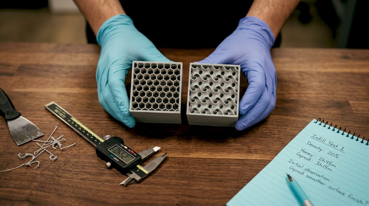
Infill pattern isn’t just a cosmetic setting. Common patterns like gyroid, grid, triangles, honeycomb, and cubic each have distinct mechanical characteristics based on how loads travel through their geometry. Choosing the wrong pattern for your application can leave performance on the table even at an appropriate density.
Here’s a breakdown of the most relevant patterns for engineering applications:
- Gyroid: A continuous, three-dimensional curved surface that distributes load in multiple directions simultaneously. Near-isotropic, meaning it resists stress from any axis without a single weak direction. Best for parts under complex, unpredictable, or multi-directional loads.
- Grid (rectilinear): Alternating lines in X and Y directions. Strong along both horizontal axes but weaker in diagonal shear. Fast to print and simple to tune.
- Triangles: Triangulated geometry within each layer, distributing planar loads across three directions. More uniform in the XY plane than grid but still directional through the Z axis.
- Honeycomb: Hexagonal cells inspired by natural structures. Excellent compressive strength perpendicular to the cell walls, making it ideal for parts that need to absorb crushing loads.
- Cubic: Interlocking cubes that provide resistance in all three spatial axes. A practical choice when parts need to handle stress from multiple directions but gyroid would take too long to print.
The differences between these patterns aren’t just theoretical. Empirical testing published in peer-reviewed research shows that infill pattern and density together produce measurably different tensile strength, mass loss, and tribological performance outcomes. Pattern selection is a real engineering decision, not a stylistic one.
For an example of how complex geometries can be leveraged in manufacturing, consider how intricate structures like a complex infill pattern example demonstrate the range of internal geometry that’s possible with thoughtful design choices.
Pro Tip: Gyroid is the go-to pattern when you genuinely don’t know the exact loading direction of a part in service. It costs slightly more in print time than grid, but the near-isotropic performance eliminates a lot of guessing during printing challenge troubleshooting. For parts with clearly defined single-axis loads, triangles or grid often deliver equivalent performance at lower print time. Understanding your load direction is one of the highest-value inputs you can bring to creative applications for developers.
Practical infill selection: Workflow for prototypes and functional parts
With patterns and density understood, here’s how experienced engineers make practical infill decisions in the real manufacturing world.
The biggest mistake product developers make is over-engineering print settings before they’ve tested a single prototype. Maxing out infill density on a first iteration wastes material, adds print time, and still doesn’t guarantee the part will survive its intended use. A structured, iterative approach produces better results faster.
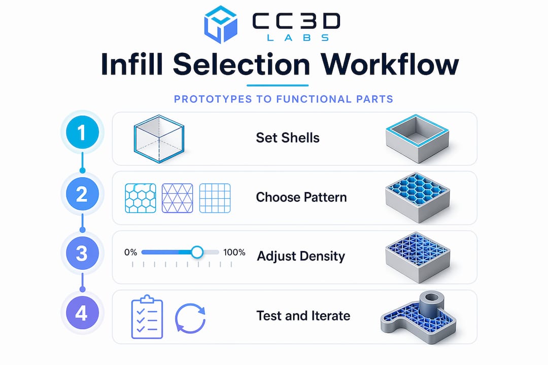
Here is a repeatable workflow for selecting infill settings on functional parts and prototypes:
- Define the loading condition. Will the part experience compression, tension, torsion, or some combination? This determines which infill pattern makes sense before you touch any software settings.
- Choose the pattern first. Multi-directional or unknown loads: gyroid. Single-axis compression: honeycomb or cubic. Speed-critical batch parts with simple planar loads: grid or triangles.
- Set a moderate starting density. For functional parts, start with 20-30% infill and increase only if testing reveals core insufficiency. This range supports top layers effectively and handles most real-world loads without waste.
- Set wall count to at least 3 perimeters before printing the first test. Walls are your primary strength contributors and cost less per unit of strength than dense infill.
- Print and test mechanically. Apply load in the expected direction, either through a physical test rig or by reviewing deflection and failure mode by hand. Look at where the part fails.
- Diagnose before adjusting density. Wall failure: add perimeters. Layer separation: increase print temperature or slow down print speed. Surface deflection: add solid top and bottom layers. Core crush or internal buckling: increase infill density, then retest.
- Document your settings for each part type. Once a configuration passes functional testing, lock it in as a baseline for that application. This builds an internal library of proven settings over time.
You can find real-world applications of this approach in filament-based prototype examples that show how different structural decisions play out in practice.
Pro Tip: Use infill primarily for two jobs: supporting the top surface layers so they bridge cleanly without sagging, and providing enough core bulk to resist compression or crushing from assembly hardware like threaded inserts. If you’re using infill as the primary source of tensile or flexural strength, your wall count is probably too low.
Why optimal infill starts with smart shell design
After working through hundreds of functional part prints, the clearest pattern we’ve seen at CC 3D Labs is this: engineers who struggle with part failures almost always focus on infill density first. Engineers who produce consistently durable parts start with shell design.
The outer shell, the perimeter walls, the top and bottom solid layers, and the bonding between those shells and the infill lattice, that assembly is doing the majority of structural work in any filament-based print. Infill is the internal scaffold that holds the shell in shape and prevents collapse. Treating it as the primary strength mechanism leads to wasted material, longer print times, and parts that still fail because the underlying wall or bonding issue was never addressed.
We also see a specific failure mode that comes from insufficient wall-to-infill overlap. When the infill doesn’t bond fully to the perimeter walls, you get microscopic gaps at the junction. Under stress, those gaps become fracture initiation points. Adding more infill density doesn’t help because the structural discontinuity is at the interface, not in the core. Tuning overlap percentage and ensuring good layer adhesion through appropriate print temperature is a far more effective fix.
The other common pitfall is printing at 80% or 100% infill on every part “to be safe.” Beyond roughly 40-50% infill on most geometry types, you’re adding significant weight and print time for negligible mechanical return. This is particularly expensive when you’re running small batch production and those inefficiencies multiply across 20 or 50 parts. A well-designed production-grade guide approach means engineering the part once with the right settings, not compensating for design uncertainty with excess material.
The practical wisdom is simple: invest time in understanding your load conditions, set your shell correctly, pick the right pattern, start at moderate density, and test. That iterative approach will consistently outperform brute-force density in both performance and cost.
Enhance your prototypes with expert infill and 3D printing services
Knowing the theory is one step. Applying it to a real part under production constraints is another.

At CC 3D Labs, we work directly with engineers and product developers to translate these infill and shell design principles into reliable, tested parts. Whether you’re iterating on a prototype or moving toward batch runs, our team applies the same structured approach covered in this guide, starting with load conditions and working through pattern and density selection to deliver parts that perform. Explore our 3D printing services to see what’s possible, browse printable prototypes and parts for application ideas, or get deeper technical context in our filament prototyping guide. Free online estimates are available so you can see cost and feasibility before committing.
Frequently asked questions
Does infill density always increase part strength?
No. The strength-vs-density relationship is not linear and shows clear diminishing returns at higher densities. Wall thickness and wall-to-infill bonding typically have a greater impact on functional strength than raw density increases.
What’s the most common infill pattern used for prototypes?
Gyroid is widely used for prototypes because it provides near-isotropic strength, meaning it resists stress uniformly in multiple directions rather than favoring a single load axis, making it a reliable default when loading conditions aren’t fully defined.
How do I choose infill settings for a functional part?
Select a pattern matched to your expected load direction, then start with moderate densities in the 20-40% range. Test mechanically, identify the actual failure mode, and adjust only the setting that addresses it rather than defaulting to higher infill.
What happens if infill doesn’t bond well to the walls?
Weak wall-to-infill bonding produces gaps and delamination risk at the wall junction, which creates fracture initiation points under load. Proper overlap percentage and print temperature settings are essential for maintaining structural continuity between infill and perimeter walls.