
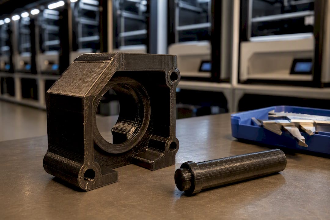
Start with a per-part offset equal to your layer height, then double it for a two-part joint. At a 0.1 mm layer height, undersize the bore by 0.1 to 0.2 mm against the shaft for a transition fit; at 0.2 mm layers, widen that starting offset proportionally. Treat this as a hypothesis, not a spec. Every printer, slicer, and material shifts the real number, so the only way to lock it in is a tolerance coupon printed on your production machine.
TL;DR:
- Bore undersize should start at twice the layer height for a transition fit at 0.1 mm layers, with larger offsets needed for thicker layers.
- Non-round geometries or added features like chamfers and slits improve press-fit forgivingness and reduce the risk of cracking or deformation.
- Layer thickness and shell count primarily influence bore accuracy, with slower perimeter speeds and consistent orientation crucial for reliable fit results.
- PETG offers a more ductile option for repeated assembly, with a 0.1 mm interference providing around 200 N force, while ABS and ASA require conservative offsets due to shrinkage and warpage.
- Testing with a tolerance coupon and recording accurate offsets ensures reliable fit, especially when precise assembly or cyclic use is involved.
Table of Contents
- What Fit Type Should You Design for in Press Fit 3D Printing?
- How Do You Design a Forgiving Press Fit?
- Which Slicer Settings Actually Change Bore Diameter?
- How Do PLA, PETG, and ABS/ASA Perform in Press Fits?
- How Do You Test and Validate a Press Fit?
- What Post-Processing Fixes a Tight Press Fit?
- Troubleshooting Checklist for Press Fit Failures
- When Should You Get a Professional Test Print or Scan?
- When Is a Printed Press Fit the Right Engineering Choice?
- Get a Test-Print Quote for Your Press-Fit Parts
- Sources
- FAQ
What Fit Type Should You Design for in Press Fit 3D Printing?
FDM designers generally work with three fit categories. A clearance fit lets the pin drop in freely, useful for parts that need to rotate or slide. A transition fit lands the pin and bore close enough that light hand pressure seats it, with enough friction to resist gravity but not enough to fight assembly. An interference fit forces material to deform slightly on insertion, producing the holding force that keeps a bearing, dowel, or shaft from working loose under vibration or load.
The University of Maryland tolerancing guide offers a workable shortcut: approximate each part’s tolerance as plus or minus the layer height, then double that value for a two-part tolerance zone. That doubled number becomes your starting undersize.
- 0.1 mm layers: start with a bore undersize roughly twice the layer height for a transition fit
- 0.2 mm layers: start with a bore undersize proportionally larger
- 0.3 mm layers: increase the starting undersize accordingly, keeping in mind rougher surfaces may reduce fit accuracy
These ranges are starting points, not universal specs. Your slicer’s flow calibration, your printer’s belt tension, even the humidity in your filament all push the real number around. Reading up on print tolerance standards before you commit to a design offset saves a lot of wasted filament later.
How Do You Design a Forgiving Press Fit?
A round pin in a round bore is the least forgiving geometry you can choose, because every micron of roundness error concentrates force unevenly around the full circumference. Switching to a non-round cross-section, an octagon or a gentle spline, concentrates contact at a few points instead of the whole perimeter, which gives the joint room to flex without cracking.
- Add a small chamfer or lead-in taper on the pin’s leading edge so it self-centers instead of catching on the bore’s first layer
- Cut a slit or thin web into a pin to add spring, especially useful on pins that need to hold tight but still come apart for service
- Drill a small central hole through a solid pin to soften it without changing its outer diameter
- Print mating parts in the same orientation so both surfaces pick up the same layer-line texture and shrinkage pattern
Pro Tip: Write the working CAD offset directly into your part file’s naming convention (e.g., “bore_dia10.15_offset0.15mm”) so the next revision doesn’t start the guesswork over from zero.
Which Slicer Settings Actually Change Bore Diameter?
A peer-reviewed hole-accuracy study found layer thickness is the dominant variable affecting printed hole diameter, with shell count as the second biggest factor. The same research reported that an optimized configuration for straight holes in that test setup used a 0.2 mm layer thickness with two shells at 50 mm/s.
- Pick one layer height and stick with it across your tolerance coupon and your production run. Switching layer heights between the two invalidates every measurement you took.
- Run at least two full shells around any bore that carries a press fit. A single shell flexes under insertion force and drifts out of tolerance.
- Slow the perimeter speed on bore walls specifically. Rushed perimeters round over and undersize the hole in ways that don’t show up until you try to seat the pin.
- Orient mating surfaces the same way on both parts so anisotropic shrinkage affects them equally.
How Do PLA, PETG, and ABS/ASA Perform in Press Fits?
Material choice changes how much margin for error you actually have, and it changes what happens when a fit runs too tight.
PLA prints stiff and holds a crisp shell profile, which makes it dimensionally predictable, but it’s brittle. A slightly overtight interference fit is more likely to crack a PLA boss than deform it, so PLA works best for one-time assembly or joints that stay protected from repeated stress.
PETG behaves more ductile under load and tolerates repeated insertion and removal without cracking. Experimental testing on bearings pressed into printed housings found a 0.1 mm interference produced roughly 200 N of assembly force with good repeatability across five cycles, while 0.2 mm interference pushed that force to roughly 450 N with no meaningful gain in reliability.
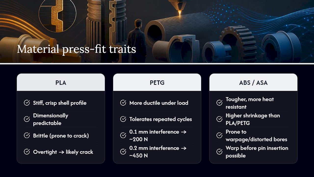
ABS and ASA run tougher and handle heat better, but their higher shrinkage means warpage can distort a bore before the pin ever gets near it. For any load-bearing or cyclic assembly, be conservative and test before committing to a production offset.
How Do You Test and Validate a Press Fit?
A tolerance coupon is a small test plate carrying a range of bores and matching pins stepped in 0.05 mm increments around your expected size. It’s the fastest way to convert a theoretical offset into a proven number.
- Design bores and pins across a span (for example, five bores from 9.95 mm to 10.15 mm against a fixed 10.00 mm pin).
- Print the coupon using the exact slicer profile, layer height, and shell count you intend for production, not a quick default setting.
- Measure the assembled interface, pin seated in bore, with calipers or a handheld scanner rather than measuring the two parts separately.
- Record insertion and removal force with a simple force gauge if one is available; that number tells you far more than diameter alone.
- Cycle the joint several times and check for dimensional creep or cracking before locking in the final offset.
An experimental study on PETG bearing housings found that a 0.1 mm interference held up across five assembly cycles with minimal permanent deformation, which is the kind of benchmark a coupon test lets you confirm on your own printer instead of assuming from someone else’s data. Once you land on numbers that work, write the CAD offsets, slicer profile, and filament batch into your job file. A step-by-step accuracy guide walks through the same measurement discipline in more detail.
What Post-Processing Fixes a Tight Press Fit?
Controlled reaming or light drilling is the fastest correction when a bore prints a few hundredths of a millimeter too small, and it’s the standard rescue for prototypes that are otherwise close to spec. Heat seating, warming the pin or softening the bore slightly before insertion, can also help, but it’s material dependent and risks distorting thin walls if overdone.
- Use light reaming for small, one-off corrections rather than redesigning the whole part
- Reserve heat seating for materials that tolerate it without warping nearby features
- Switch to a mechanical insert (heat-set or press-in) when the joint will see repeated cycles or higher loads than the plastic alone should carry
- Treat adhesive bonding as a last resort, since a bonded joint can’t be serviced later
Pro Tip: If you find yourself reaming the same bore on every print run, that’s a design signal, not a process fix. Widen the nominal clearance instead of relying on a post-process rescue every time.
Troubleshooting Checklist for Press Fit Failures
When a fit doesn’t seat right, work through the likely causes in this order before touching the CAD file:
- Confirm you measured the assembled interface, not the bore and pin diameters separately
- Verify the coupon used the same orientation and slicer settings as the production run
- If parts keep cracking or deforming, reduce interference, switch material, or move to a mechanical insert
- Log the final working CAD offset and full process settings once a fit performs consistently
When Should You Get a Professional Test Print or Scan?
High-stakes press fits, ones holding a bearing, a sensor, or a part that can’t be reprinted twice, deserve a second set of eyes and equipment beyond a desktop printer. CC 3D Labs runs a Bambu Lab FDM production farm and offers professional handheld 3D scanning (accuracy to ~0.1 mm) for verifying an assembled interface against your CAD model.
- Send an STL, your nominal fit dimensions, material preference, and expected assembly cycle count when requesting a quote
- Every job is quoted after a test print of your actual part, so the number you get reflects your geometry, not a generic estimate
- Scan-to-CAD checking confirms whether the printed bore matches design intent before you commit to a full production run
When Is a Printed Press Fit the Right Engineering Choice?
Printed press fits earn their place on prototypes, low-cycle assemblies, and parts where a slight adjustment in offset is cheap to iterate. Once a joint faces repeated disassembly, high torque, or sustained load, a mechanical insert or fastener is the more durable call. Either way, the number that matters is the one measured on your own coupon, recorded alongside the exact process settings that produced it.
— Justin
Get a Test-Print Quote for Your Press-Fit Parts
CC 3D Labs is built for the exact problem this guide walks through: turning a theoretical offset into a proven one on real hardware. Instead of guessing at tolerances from a spec sheet, you get a Bambu Lab FDM production run quoted only after a test print of your actual geometry, backed by professional handheld 3D scanning (accuracy to ~0.1 mm) when you need the assembled interface verified against your CAD model rather than assumed.
If your part needs reverse-engineered CAD before it can even be printed, that scan-to-CAD workflow runs through the same services page as the printing work. Send your STL, your target fit type, and your material preference, and request a test-print quote to get a number based on your actual part instead of a generic tolerance table.
Sources
- Tolerancing – University of Maryland
- Investigations on Factors Affecting 3D-Printed Holes Dimensional Accuracy and Repeatability
- Influence of press-fit dimensions on repeated assembly of ball bearings into 3D printed housings
FAQ
How Much Tolerance Should I Use for Press Fit 3D Printing?
Start with a per-part offset equal to your layer height and double it for the two-part fit, per the University of Maryland guide, so a 0.1 mm layer height suggests a 0.1 to 0.2 mm bore undersize as a first estimate. That number only becomes reliable once you confirm it with a tolerance coupon on your own printer and material.
Is Anything Illegal to 3D Print?
Yes. Certain items, including untraceable firearms and components restricted under federal and state law, are illegal to manufacture regardless of the method used to make them. Press-fit design questions themselves are unrelated to legality; the concern applies to specific restricted objects, not the printing process.
Can I Drink Out of a PETG Cup?
PETG is generally considered food-safe as a raw material, but a printed cup has layer lines and micro-gaps that trap bacteria and are difficult to fully sanitize, so most functional-parts practitioners avoid using printed vessels for regular drinking. A press-fit application involving PETG, like a bearing housing, carries no such food-contact concern.
Can ChatGPT Actually Make STL Files?
No. Large language models generate text, not the mesh geometry an STL file requires, so ChatGPT cannot output a usable 3D print file directly. Designing press-fit geometry still requires CAD software or a modeling service; CC 3D Labs offers 3D modeling and CAD services for readers who need a model built from scratch or reverse-engineered from a scan.