
TL;DR:
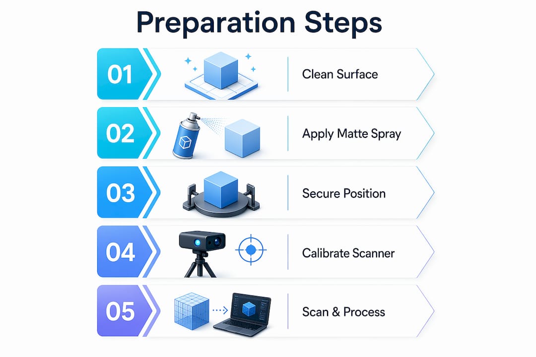
- Proper 3D scan model preparation relies on surface control, stable positioning, and proper reference data to ensure a clean, accurate mesh. Applying matte coatings improves data quality on reflective or dark surfaces, while irregular marker placement and secure fixtures prevent tracking errors and model shifts. Effective post-scan processing includes cleaning, decimating, and retopologizing meshes, with appropriate file formats chosen based on the intended use.
Proper 3D scanning model preparation is the single biggest factor separating a clean, usable mesh from a session full of noise and gaps. Knowing how to prepare models for scanning means controlling three variables before the scanner ever fires: surface condition, physical stability, and reference data. Skip any one of them and you will spend more time fixing the mesh than you saved by rushing setup. This guide covers surface treatment with sprays like AESUB Blue, positioning with turntables and adhesive markers, post-scan processing in tools like Blender and MeshLab, and the troubleshooting moves that save a scan session when things go sideways.
How to prepare models for scanning: surface and material basics
The surface your scanner sees determines the quality of the data it captures. Shiny, reflective, transparent, and very dark surfaces all cause the same core problem: the scanner cannot resolve a consistent return signal, so it either skips those areas entirely or fills them with noise.
The surfaces that cause the most trouble are:
- Highly polished metals (chrome, brushed aluminum, mirror steel)
- Clear or translucent plastics (acrylic, polycarbonate, glass)
- Jet-black or very dark matte surfaces (absorb structured light)
- Organic materials with subsurface scatter (skin, wax, rubber)
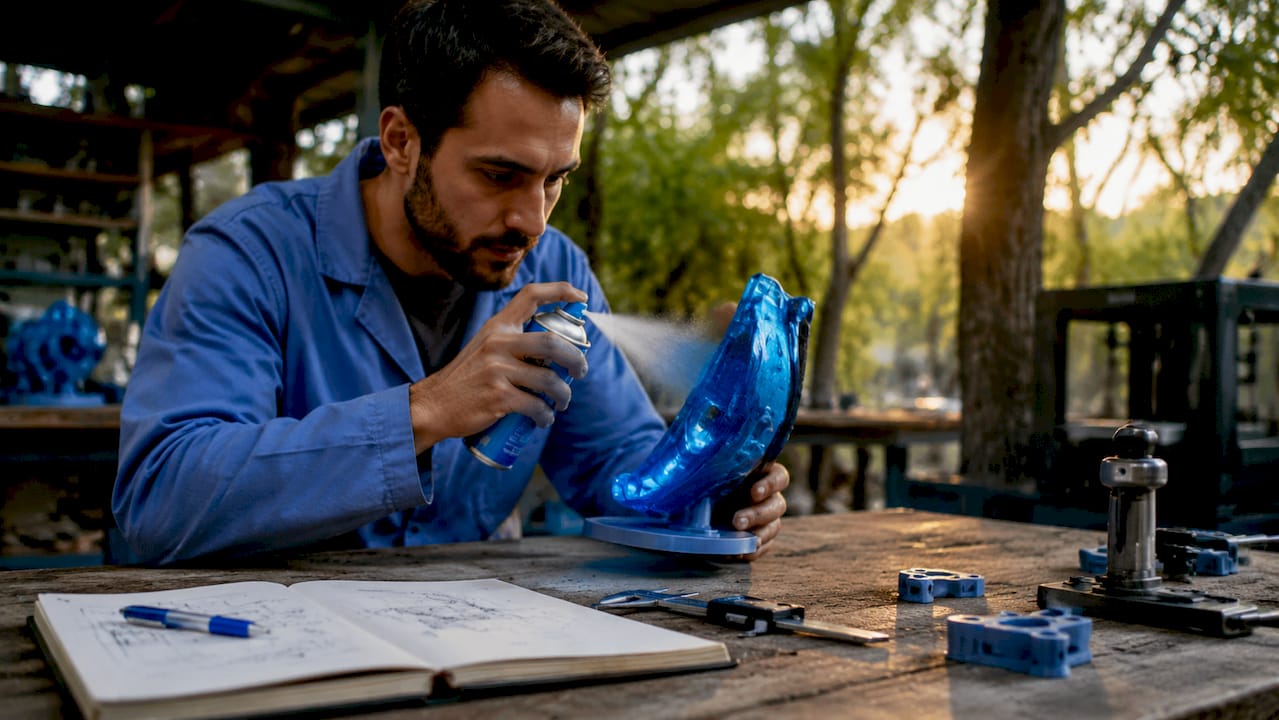
The fix for nearly all of these is a temporary matte coating. Professional scanning sprays like AESUB Blue deposit a micron-thin powder layer that gives the scanner a uniform, diffuse surface to read. AESUB Blue is self-sublimating, meaning it evaporates within a few hours without leaving residue. Dry shampoo is a widely used field substitute when a dedicated spray is unavailable. Both work by breaking up specular reflection.
Apply the spray in short, even passes from about 30 centimeters away. The goal is a uniform frost, not a thick coat. Thick coats add measurable material to the surface and obscure fine detail like text, threads, and sharp edges.
Pro Tip: Test your spray on a scrap piece of the same material before coating the actual model. Some plastics react with aerosol propellants and develop a haze that does not sublimate cleanly.
Matte gray and light tan surfaces scan without any coating in most cases. If you are working with a high quality scan for manufacturing, confirm the surface finish requirement before applying anything that could alter dimensional accuracy.
How to position and secure models for accurate scanning
Model movement during a scan is the fastest way to destroy data quality. Even a fraction of a millimeter of shift between passes creates misaligned point clouds that no software can fully correct in post-processing.
Follow these steps to lock down your setup before scanning begins:
- Place the model on a turntable. Motorized turntables let you rotate the object consistently while keeping the scanner stationary. This produces more uniform coverage than moving the scanner around a fixed object.
- Use fixtures or clamps for irregular shapes. Flexible arms and foam cradles hold odd geometries without deforming them. Turntables and fixtures prevent the movement that reduces scan accuracy most.
- Apply adhesive reference markers before scanning. Place them on flat or featureless areas where the scanner has little natural geometry to track. At least 5 markers must be visible in the scanner’s field of view at all times to maintain positional accuracy.
- Distribute markers irregularly. Symmetric or evenly spaced markers confuse the scanner’s feature-tracking algorithm. Irregular marker placement is what enables reliable tracking across featureless geometry.
- Plan for deep holes and grooves separately. These areas require dedicated scan passes at oblique angles. Do not expect a single turntable rotation to capture internal geometry.
Pro Tip: Flexible clamps are useful for holding thin or delicate parts, but tighten them only until the part stops moving. Overtightening deforms flexible materials and introduces dimensional error that shows up in the final mesh.
For complex assemblies, consider scanning sub-components separately and merging the point clouds in software. This approach gives you better coverage of internal features and reduces the total number of scan passes needed per session.
Which tools and accessories improve scanning efficiency?
The right accessories reduce setup time and improve first-pass data quality. Here is a comparison of the core tool categories and what to look for in each:
| Tool Category | Budget Option | Professional Option | Key Consideration |
|---|---|---|---|
| Scanning spray | Dry shampoo | AESUB Blue | Self-sublimating sprays preserve dimensions |
| Turntable | Manual photography turntable | Motorized scanning turntable | Motorized units produce consistent rotation speed |
| Lighting | Daylight LED panels | Controlled LED ring lights | Even lighting without shadows reduces geometric artifacts |
| Reference markers | Generic dot stickers | Coded photogrammetry targets | Coded targets give software absolute position data |
| Scanner mount | Tripod | Articulating arm | Arms allow faster repositioning for complex geometry |
Lighting deserves more attention than most guides give it. Harsh directional light creates shadows that the scanner reads as geometry. The result is false surface detail baked into your mesh. Use two or more diffuse LED panels positioned at 45-degree angles to the object. This eliminates most shadow artifacts without washing out surface texture.
For photogrammetry workflows specifically, camera settings matter as much as lighting. Shoot at ISO 100–400, use a small aperture (f/8–f/11) for depth of field, and keep shutter speed fast enough to avoid motion blur. Consistent exposure across all frames is what allows photogrammetry software like RealityCapture or Metashape to align images accurately.
What are the key steps in post-scan mesh processing?
Raw scan data is not a finished model. Raw scan meshes can contain several million polygons, which is far more than any downstream workflow needs and too heavy for most software to handle efficiently.
Here is the standard processing sequence:
- Clean the raw mesh. Remove floating points, isolated clusters, and obvious scan artifacts. Tools like MeshLab and Blender’s Clean Up functions handle this well for most scan types.
- Fill holes selectively. Small holes from marker removal or occluded geometry can be filled. Avoid aggressive hole-filling on scan data destined for CAD. Aggressive smoothing or hole-filling reduces physical accuracy in CAD workflows.
- Decimate the mesh. Decimation targets 5–10% of the original polygon count before retopology. A 10-million-polygon raw scan becomes a 500,000 to 1,000,000-polygon working mesh.
- Retopologize for your use case. Production models for animation need quad-dominant meshes with proper edge loops. Retopology should combine automated tools and manual refinement for production-ready results. Blender’s Shrinkwrap modifier is a reliable starting point for manual retopology over a decimated base.
- Export in the correct format. OBJ and STL work for most 3D printing workflows. STEP or IGES is required for CAD integration. Aligning scan data within CAD software using planes and cross-sections produces the most accurate sketches for modeling.
| Processing Stage | Recommended Tool | Output |
|---|---|---|
| Mesh cleanup | MeshLab, Blender | Clean, artifact-free mesh |
| Decimation | MeshLab, ZBrush | Reduced polygon mesh |
| Retopology | Blender, Wrap3 | Quad-dominant production mesh |
| CAD alignment | SolidWorks, Fusion 360 | Dimensionally accurate CAD model |
Before you retopologize, analyze the asset’s intended use to set the right polygon budget. A real-time game asset needs a fraction of the polygons that a film-quality render requires. Getting this decision right before retopology saves hours of rework.
What common challenges arise during scanning preparation?
Even well-prepared scans run into problems. Knowing what to look for before you start saves significant time in post-processing.
The most frequent issues and their fixes:
- Reflective surfaces still causing noise after spraying. Apply a second thin coat and wait 60 seconds before scanning. If noise persists, the surface may need a different spray chemistry or a physical matte film.
- Markers not being tracked reliably. Check spacing and pattern. Markers placed in a grid or at equal intervals reduce tracking robustness. Redistribute them in a random, asymmetric pattern.
- Model shifting mid-scan. Stop the session immediately. Reposition and re-secure the model, then restart. Attempting to merge a shifted scan in software produces unreliable results.
- Incomplete coverage on complex geometry. Plan additional scan passes at oblique angles before the main session. Undercuts, deep channels, and internal cavities almost always need dedicated capture angles.
- Noisy or spiky mesh output. This usually points to inadequate lighting or surface coating. Review your lighting setup and check for reflections from nearby surfaces, walls, or equipment.
The most overlooked step in scanning preparation is a dry run. Scan a simple test object with the same surface treatment and lighting before committing to the actual model. This catches lighting and coating problems in minutes rather than hours.
Iterative testing is the professional standard, not a sign of inexperience. Aerospace and precision manufacturing workflows, for example, routinely include test scans of reference geometry before scanning the actual part. This practice validates the entire setup, from lighting to marker placement to scanner calibration, before the critical scan begins.
Key takeaways
Effective 3D scanning model preparation requires surface treatment, stable positioning, and disciplined post-scan processing to produce accurate, usable mesh data.
| Point | Details |
|---|---|
| Surface coating is non-negotiable | Apply matte sprays like AESUB Blue to reflective, transparent, or dark surfaces before scanning. |
| Marker placement must be irregular | Place at least 5 reference markers in an asymmetric pattern to maintain scanner tracking accuracy. |
| Secure the model completely | Use turntables and fixtures to eliminate movement that corrupts point cloud alignment. |
| Decimate before retopology | Reduce raw meshes to 5–10% of original polygon count before rebuilding topology for production use. |
| Preserve raw data for CAD | Avoid aggressive smoothing or hole-filling on scan data going into CAD workflows to protect dimensional accuracy. |
What i have learned preparing models for professional scans
The part of scanning preparation that most guides undervalue is patience at the setup stage. Every minute spent checking marker placement, coating uniformity, and lighting angles saves at least ten minutes of mesh repair. That ratio holds whether you are scanning a small figurine or a full automotive component.
The other thing I have found consistently true: the tools matter less than the process. I have seen clean, usable scans produced with a budget turntable and dry shampoo, and I have seen expensive scanner sessions produce unusable data because nobody checked the lighting. The scan accuracy optimization process is repeatable and learnable. The technology is not magic.
AI-assisted retopology tools are genuinely changing the post-processing side of this work. What used to take a skilled artist several hours of manual retopology can now be roughed out in minutes with tools like Tripo3D’s AI retopology, then refined by hand. The human judgment still matters for edge loops around joints and deformation areas, but the grunt work is increasingly automated.
My honest advice: build a preparation checklist specific to your scanner and your most common object types. Laminate it. Use it every session. The professionals who produce the most consistent scan data are not the ones with the best equipment. They are the ones with the most disciplined setup habits.
— Justin
Get professional scanning results with Cc3dlabs
Preparation expertise only goes so far when the geometry is complex or the tolerances are tight. Cc3dlabs operates a full 3D scanning lab near Philadelphia, handling metrology-grade scanning, surface preparation, and complete post-scan processing for prototypes, functional parts, and production components.

Whether you need a single part scanned and converted to a CAD-ready model or a batch of components processed for manufacturing, Cc3dlabs manages the full workflow from physical model to finished file. The team also provides 3D printing services to take your scan data directly into production. Request a free estimate online or arrange local pickup to get started.
FAQ
What surfaces are hardest to scan accurately?
Highly reflective metals, clear plastics, and jet-black surfaces cause the most scanning problems because they scatter or absorb the scanner’s light source. Apply a temporary matte coating like AESUB Blue to resolve most surface-related scan failures.
How many reference markers do i need for a scan session?
At least 5 adhesive reference markers must be visible in the scanner’s field of view at all times. Place them in an irregular, asymmetric pattern so the scanner’s tracking algorithm can distinguish individual markers reliably.
What is the right polygon count after decimation?
Target 5–10% of the raw scan’s original polygon count as your working mesh before retopology. The final polygon budget depends on the intended use: real-time assets need far fewer polygons than film or archival models.
Should i fill holes in my scan mesh before importing to CAD?
Avoid aggressive hole-filling on scan data going into CAD workflows. Filling holes can alter surface geometry and reduce dimensional accuracy. Keep the mesh non-watertight and handle geometry reconstruction inside the CAD environment instead.
What file format should i export for 3d printing versus CAD?
Export STL or OBJ for 3D printing workflows. Use STEP or IGES when the scan data needs to integrate with CAD software like SolidWorks or Fusion 360 for precise modeling and assembly work.