

TL;DR:
- Wall thickness in 3D printing refers to the solid outer perimeter layers that define a part’s boundary, separate from internal infill. Properly setting wall thickness ensures parts are strong, accurate, and durable, avoiding failures like cracking or warping. It is best designed as a multiple of the nozzle diameter, tailored to the specific material and technology used for optimal print reliability.
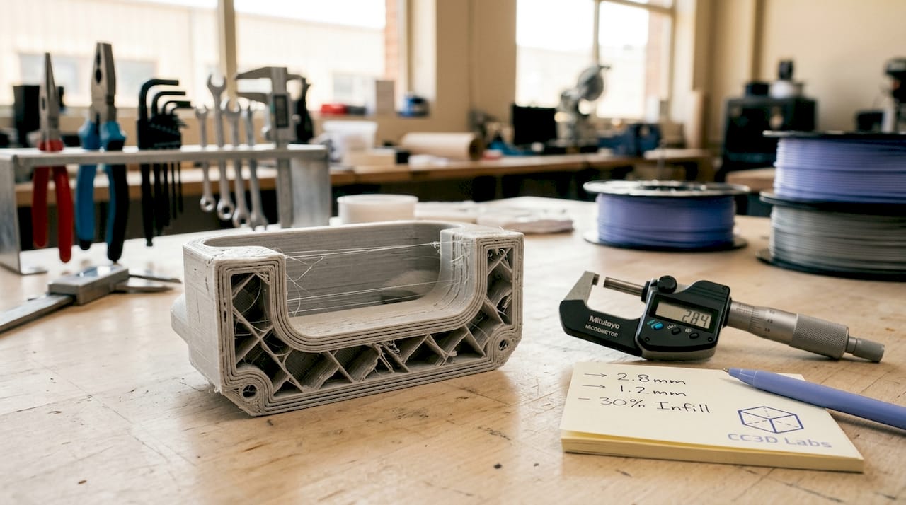
Wall thickness in 3D printing is defined as the measurement of the outer solid perimeter layers that form a part’s boundary, separate from the internal infill structure. This single parameter shapes whether a printed part survives real-world use or fails on first contact with stress. Get it wrong and you waste material, time, and filament on a part that cracks, warps, or prints with gaps. Get it right and you unlock prints that are strong, accurate, and built for their intended purpose. This guide covers what wall thickness means, how it interacts with your slicer and material, and how to dial it in for any print.
What is wall thickness in 3D printing?
Wall thickness is the outer shell thickness of a 3D printed part, forming the solid boundary between the part’s surface and its interior infill. It is not the same as infill density, and confusing the two is one of the most common mistakes in print design. Infill fills the interior volume at a chosen density pattern. Wall thickness defines the solid outer frame that holds everything together.
Some sources draw a further distinction between wall thickness and shell thickness. Wall thickness refers specifically to the vertical perimeters running along the sides of a part. Shell thickness includes those vertical walls plus the top and bottom solid layers. Understanding this difference matters when you are configuring a slicer, because the two settings are adjusted independently and affect different aspects of part performance.
Wall thickness also connects directly to nozzle diameter and layer height. A printer running a 0.4 mm nozzle extrudes lines of roughly that width, so every wall is built from stacked extrusion lines. This relationship between hardware and geometry is why wall thickness is not just a design choice but a printing parameter with physical constraints.
How wall thickness varies by technology and material
Minimum wall thickness values differ significantly across printing technologies because each process uses different physics to build parts. FDM (Fused Deposition Modeling) typically requires a minimum of 0.8 to 1.2 mm. SLA resin printing can go as thin as 0.5 mm. SLS Nylon powder bed printing sits around 0.7 to 1 mm. Metal DMLS processes require 1 to 2 mm due to thermal stress and sintering behavior.
These differences exist because powder bed and resin technologies support the part during printing, allowing thinner walls without collapse. FDM parts are built layer by layer in open air, requiring more material to maintain structural integrity during the print itself. This means a wall thickness that works perfectly in SLA will fail to print reliably in FDM on the same geometry.
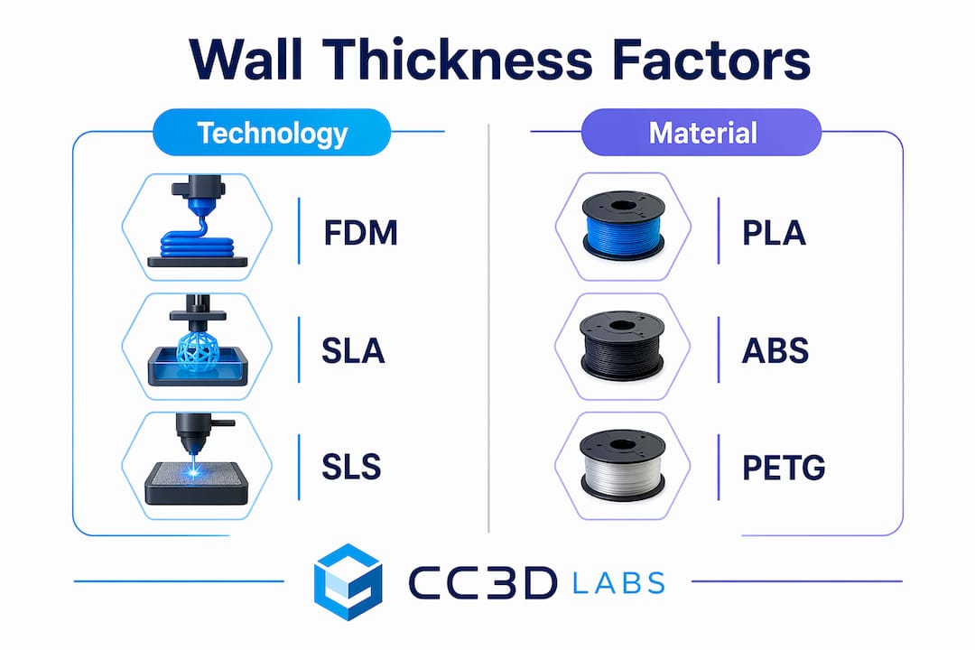
Material choice adds another layer of complexity. PLA is stiff and prints well at thinner walls. ABS and PETG require slightly thicker walls to compensate for their tendency to warp or delaminate under stress. TPU, being flexible, needs thicker walls to maintain shape and resist tearing. Metal and engineering-grade materials demand the most conservative minimums because the consequences of failure are more severe.
The table below summarizes typical minimum wall thickness values by technology:
| Technology | Material | Minimum wall thickness |
|---|---|---|
| FDM | PLA, ABS, PETG | 0.8 to 1.2 mm |
| SLA | Standard resin | 0.5 mm |
| SLS | Nylon | 0.7 to 1.0 mm |
| DMLS | Metal alloys | 1.0 to 2.0 mm |
| FDM | TPU (flexible) | 1.5 to 2.0 mm |
Load-bearing parts and components that will be post-processed (sanded, painted, or drilled) should always target the upper end of these ranges. Visual models or display pieces can use minimums. The intended function of the part, not just the material, determines where in the range you should land.
Wall thickness vs. wall count vs. shell thickness in slicers
Slicer software like Orca Slicer, PrusaSlicer, and Bambu Studio each use slightly different terminology, but the underlying concepts are consistent. Understanding how these three terms relate to each other prevents costly misconfigurations.
Here is how the terms break down:
- Wall thickness is the total width of the outer perimeter. It equals the number of wall lines multiplied by the extrusion width.
- Wall count (also called perimeter count or wall line count) is the number of extrusion lines that form the outer shell. A 0.5 mm nozzle printing a 1.5 mm wall uses 3 wall lines.
- Shell thickness is the broader term that includes both the vertical walls and the top and bottom solid layers. Adjusting shell thickness in a slicer changes how many solid layers cap the top and bottom of the part.
For a 0.4 mm nozzle, a wall count of 2 produces a wall thickness of approximately 0.8 mm. A wall count of 3 produces 1.2 mm. This is why designing walls as multiples of the nozzle diameter avoids gaps and weak points in the perimeter. A wall designed at 1.0 mm with a 0.4 mm nozzle forces the slicer to either squeeze in 2.5 lines (impossible) or adjust the extrusion width, which can introduce inconsistencies.
Slicers also enforce minimum printable widths. When a wall in your model is thinner than the nozzle diameter, the slicer may omit or adjust it entirely, creating a discrepancy between your CAD design and the actual printed part. This is a frequent source of confusion when thin features disappear in the print preview.
Pro Tip: Set your wall thickness to an exact multiple of your nozzle diameter before slicing. For a 0.4 mm nozzle, use 0.8 mm, 1.2 mm, or 1.6 mm. This eliminates extrusion width adjustments and produces the most consistent perimeters.
How wall thickness affects strength, durability, and print reliability
Walls are the primary structural framework of any 3D printed part. Thicker walls strengthen parts more reliably than increasing infill alone, because the outer perimeters carry the majority of bending, tensile, and compressive loads. A part with 15% infill and 3 wall lines will outperform a part with 50% infill and 1 wall line in most real-world load scenarios.
The risks of getting wall thickness wrong fall into two categories:
- Too thin: Walls below the technology minimum produce incomplete perimeters, visible gaps, delamination under stress, and failed prints. Thin walls on FDM parts are especially vulnerable to layer separation when the part is flexed or dropped.
- Too thick: Walls that are excessively thick increase print time, material cost, and part weight without proportional strength gains. They can also cause warping in materials like ABS because the greater mass retains heat unevenly during cooling.
Wall thickness also interacts with post-processing. Parts that will be sanded, drilled, or threaded need extra wall material to survive the process without breaking through to infill. A threaded insert pressed into a wall thinner than 2 mm will crack the perimeter. For heat-resistant applications, thicker walls slow thermal transfer and protect the part’s geometry under sustained load.
“Wall thickness should be treated as a primary design variable, with infill secondary, to ensure structural integrity.” — BigRep Design Guide
Pro Tip: For functional parts that will experience repeated stress, use a minimum of 3 wall lines regardless of material. This creates a perimeter thick enough to distribute load across multiple extrusion paths rather than concentrating stress on a single line.
For a deeper look at how infill patterns and wall settings work together, the infill and strength guide at Cc3dlabs covers the interaction in detail.
How to measure and optimize wall thickness in your designs
Measuring wall thickness starts in your CAD software before the file ever reaches a slicer. Tools like Fusion 360, SolidWorks, and FreeCAD all include wall thickness analysis features that flag areas below a specified minimum. Running this check before export catches problems that would otherwise only appear as failed prints.
Once in the slicer, the preview mode shows exactly how walls are being interpreted. Thin wall detection in Orca Slicer and PrusaSlicer highlights areas where the slicer has modified or dropped wall lines. These highlighted zones are where your print will be weakest.
Follow these steps to optimize wall thickness systematically:
- Start with nozzle multiples. Set your initial wall thickness to 2x or 3x your nozzle diameter and adjust from there based on part function.
- Run a test print. Print a small cross-section of your part’s most complex geometry before committing to a full print. This reveals slicer behavior in tight areas.
- Check wall distribution in complex geometry. Curved surfaces and narrow features cause slicers to adjust effective wall width locally. Review the layer preview at multiple heights.
- Use a minimum wall thickness calculator for engineering parts. These tools factor in material, process, and feature size to recommend a practical minimum that avoids manufacturing defects.
- Iterate with purpose. Change one variable at a time. Adjust wall count, reprint the test section, and evaluate before changing material or layer height.
For parts with varying cross-sections, such as brackets with thin flanges and thick bosses, consider using variable wall thickness in your CAD model rather than relying on a single slicer setting. This gives you precise control over where material is concentrated and where it is not.
Pro Tip: When designing for reliable prototypes and functional parts, model your wall thickness explicitly in CAD rather than relying on slicer wall count settings alone. Explicit geometry gives you full control and eliminates slicer interpretation errors.
Key takeaways
Wall thickness is the single most important structural variable in 3D print design, and setting it as a multiple of nozzle diameter while matching it to your technology and material is the fastest path to reliable, strong parts.
| Point | Details |
|---|---|
| Wall thickness definition | The outer solid perimeter of a printed part, distinct from infill and shell top/bottom layers. |
| Technology-specific minimums | FDM needs 0.8 to 1.2 mm; SLA can use 0.5 mm; DMLS metals require 1 to 2 mm. |
| Nozzle diameter rule | Design walls as exact multiples of nozzle diameter to prevent gaps and slicer adjustments. |
| Walls over infill for strength | Three wall lines outperform high infill for load-bearing parts in most stress scenarios. |
| Measure before you print | Use CAD wall analysis and slicer preview tools to catch thin-wall issues before the first layer. |
Why wall thickness is the variable most designers underestimate
After working with hundreds of 3D printed parts across FDM, SLA, and SLS processes, the pattern I see most often is this: designers spend hours tuning infill density and layer height, then set wall count to 2 and wonder why the part breaks. Wall thickness is not a secondary setting. It is the structural backbone of the print.
The misconception that infill drives strength is persistent and understandable. Infill is visible in slicer previews, it has named patterns (gyroid, honeycomb, grid), and it feels like the “meat” of the part. But the walls are what transfer load from the surface to the interior. A part with thin walls and dense infill is like a building with thick floors and paper-thin exterior walls. The interior can be solid, but the structure still fails at the boundary.
What I have found in practice is that most functional parts benefit from 3 to 4 wall lines, regardless of material. This is not a universal rule, but it is a reliable starting point that holds across PLA, PETG, and ABS. For flexible materials like TPU, I go to 5 or 6 lines because the flex itself distributes stress across the perimeter in ways that thinner walls cannot absorb.
The other thing most guides skip is the interaction between wall thickness and post-processing. If you plan to sand, paint, or insert hardware into a part, you are removing or stressing material that the slicer assumed would be there. Add at least one extra wall line for any part that will be post-processed. It costs almost nothing in print time and prevents a frustrating reprint.
For anyone dealing with material-specific wall challenges, the practical advice is always the same: test a cross-section first, measure the result, and adjust before printing the full part.
— Justin
Get expert wall thickness guidance from Cc3dlabs
Cc3dlabs brings professional-grade expertise to every print, including the wall thickness decisions that determine whether a part performs or fails.

Whether you are prototyping a functional bracket, producing a batch of custom enclosures, or validating a design before manufacturing, Cc3dlabs’ team near Philadelphia handles the full process. From material selection and wall thickness optimization to multi-color FDM and metrology-grade scanning, every project gets the attention it needs to print right the first time. Explore professional 3D printing services at Cc3dlabs and get a free online estimate for your next project.
FAQ
What is wall thickness in 3D printing?
Wall thickness is the measurement of the solid outer perimeter layers of a 3D printed part, forming its structural boundary separate from the internal infill. It directly determines part strength, surface quality, and print reliability.
What is the minimum wall thickness for FDM printing?
FDM printing typically requires a minimum wall thickness of 0.8 to 1.2 mm, depending on material. Functional or load-bearing parts should target the upper end of this range to avoid delamination and structural failure.
How does wall count differ from wall thickness?
Wall count is the number of extrusion lines forming the perimeter, while wall thickness is the total width of those lines combined. For a 0.4 mm nozzle, a wall count of 3 produces a wall thickness of approximately 1.2 mm.
Should I increase wall thickness or infill for stronger prints?
Increasing wall thickness produces stronger parts more reliably than increasing infill alone, because walls form the primary structural framework that carries bending and tensile loads. Start with 3 to 4 wall lines before adjusting infill density.
How do I measure wall thickness in my 3D model?
Use the wall thickness analysis tools in CAD software like Fusion 360 or SolidWorks to identify areas below your target minimum before exporting. After slicing, use the layer preview in Orca Slicer or PrusaSlicer to confirm walls are being printed as designed.