
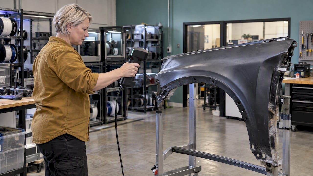
A handheld 3D scanner’s accuracy figure is the closeness of its measurements to the true dimensions of a part, under the specific conditions the manufacturer tested. It is not a promise about every scan. Advertised figures commonly fall somewhere between a few hundredths and a few tenths of a millimeter, but the same scanner can deliver very different results depending on part size, geometry, surface finish, calibration and technique. At CC 3D Labs we offer professional handheld 3D scanning (accuracy to ~0.1 mm), and this guide explains how to read accuracy claims, what degrades them, and how to decide whether a scan is good enough for your tolerance.
TL;DR
- Accuracy means closeness to the true dimension. Precision means consistency, and resolution means the smallest detail the scanner can sample. They are three separate properties.
- A spec sheet figure is a conditional result from a defined test. Peer-reviewed testing found that manufacturer specifications were not met by every handheld scanner in every scenario.
- Volumetric accuracy, which covers the whole scanned volume, matters more than single-shot accuracy once a part is larger than a hand.
- Verify against a known reference, such as a calibrated artifact or a CMM-measured part, and match the scan’s accuracy to the tolerance you actually need.
- For FDM reproduction, a scan accurate to ~0.1 mm sits comfortably inside the typical ±0.2–0.5 mm that FDM printing holds.
Table of Contents
- What a handheld scanner’s accuracy number actually measures
- Accuracy, precision, resolution and repeatability
- Single-shot accuracy versus volumetric accuracy
- What degrades accuracy in a real scan
- How to compare scanners or scan results fairly
- How to verify a scan against a known reference
- Is the accuracy enough for your tolerance?
- Our perspective on handheld scanner accuracy
- Have a part you need scanned or reproduced?
- FAQ
- Sources
What a handheld scanner’s accuracy number actually measures
When a datasheet says 0.05 mm, it describes a deviation measured against a reference under test conditions. The number says nothing on its own about the part in front of you. Three questions turn it into something useful: what was measured, how large was the measured volume, and under what conditions.
The research is blunt on this point. A 2018 comparative investigation published by ISPRS found that manufacturer accuracy specifications were not reached by all the tested handheld scanners in every test scenario. The authors’ conclusion is that accuracy is specific to the model, the object, the workflow and the test conditions, so a figure should not be generalized beyond the system and scenario that produced it.
That does not make advertised numbers meaningless. It means they are a ceiling achieved in good conditions, and your job is to understand how far your own conditions sit from those.
Accuracy, precision, resolution and repeatability
These four terms get mixed up in sales copy, and mixing them up leads to buying decisions (or vendor choices) based on the wrong property. Standard metrology definitions, as summarized by Test & Measurement Tips, are:
- Accuracy: closeness of a measurement to the reference value.
- Precision: consistency across repeated measurements.
- Repeatability: variation when the same person measures with the same instrument under the same conditions.
- Reproducibility: variation when different operators or conditions are involved.
| Property | Question it answers | What a failure looks like |
|---|---|---|
| Accuracy | Is the dimension right? | A bore scans consistently 0.3 mm undersized |
| Precision | Do repeat scans agree? | Three scans of one part give three different diameters |
| Resolution | How fine a detail can be sampled? | Small ribs and text edges look rounded or missing |
| Repeatability | Can the same operator get the same result tomorrow? | Results drift between sessions |
A scanner can be precise but inaccurate if it consistently reports the wrong value, and accurate on average but imprecise if individual results scatter. For reverse engineering you generally need both.
Resolution is not accuracy
This is the most common source of confusion behind the query “3D scan resolution vs accuracy.” Resolution describes the spacing of sampled points or the smallest detail that can be detected. Accuracy describes whether those points sit in the right place in space. A dense, beautiful-looking mesh can still be dimensionally wrong, for example if the overall shape has stretched slightly across a long part. Treat resolution as a statement about detail capture, such as small fillets, thin ribs and engraved features, and treat accuracy as a statement about dimensions.
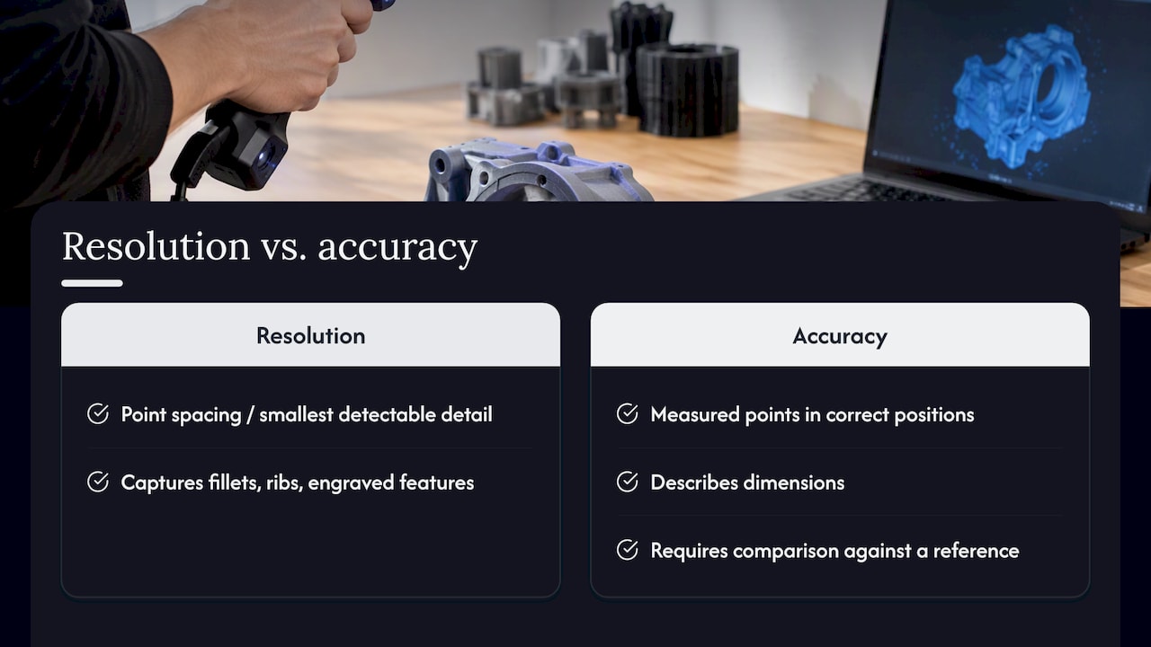
A practical consequence: a mesh with millions of triangles is not evidence that your 25.00 mm bore is really 25.00 mm. Only a comparison against a reference can show that.
Single-shot accuracy versus volumetric accuracy
Manufacturers often quote two kinds of figure, and the difference matters for anything larger than a palm-sized part.
- Single-shot (per-point) accuracy describes how close one capture is to the true surface. It is typically the more flattering number.
- Volumetric accuracy describes error accumulated across the combined measurement volume as the scanner is moved, frames are stitched together and the part grows. It is usually expressed as a base value plus a per-meter term.
An example of how this looks on a spec sheet: the 2021 peer-reviewed evaluation of a high-end handheld laser scanner, using a ball-lattice artifact, reported a mean absolute distance error of 0.009 mm with a standard deviation of 0.013 mm across 46,440 cases. That is an excellent result, but it came from a controlled artifact test on a specific system, and it should be read as a demonstration of what careful testing can show, not as a number any handheld scanner will reproduce on a cast housing.
The rule of thumb is simple. Error grows with size. A scan of a 40 mm bracket and a scan of a 900 mm fender section from the same scanner will not carry the same uncertainty, even though both use the same scanner and the same “accuracy” figure on the box.
What degrades accuracy in a real scan
The research identifies several repeatable influences, and they match what we see on production scanning jobs.
Calibration
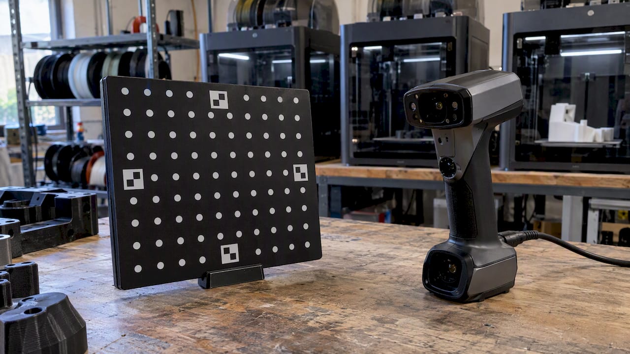
Handheld scanners depend on calibration to know their own optical geometry. The user manual for one widely used structured-light scanner, the EinScan Pro HD manual, recommends recalibrating after device changes, rough transportation, declining accuracy, or 15 days without calibration. Whatever scanner is used, a shop that scans for dimensional work should be able to tell you when it was last calibrated and how it checks itself.
Geometry and surface
The ISPRS studies found that results varied by test object. In the 2018 work, complex wheel-hub geometry produced registration-related deviations. A 2022 ISPRS study of handheld systems under VDI 2634 likewise found higher deviations in complex object areas and concluded that meeting the standard’s suitability values cannot be guaranteed for complex regions. Deep pockets, thin walls, sharp internal corners and undercuts are where error concentrates.
Surface finish matters too. A 2026 study from Queen’s University Belfast reports that specular reflections can create ghost points and edge flares, while dark or transparent materials can give sparse or incomplete point clouds. It also reports that matte or anti-glare sprays reduce reflection noise, with an example spray layer of 0.007 mm. Chrome trim, polished aluminum, black rubber and glossy paint are the typical trouble spots on automotive work.
Markers, registration and operator movement
The 2018 study documents effects from marker placement, registration conditions and operator movement. Scanning a long, featureless part, such as a straight bracket or a smooth tube, gives the software little to align frames against. Reference targets and a deliberate scan path reduce drift. Our own guide to optimizing 3D scan accuracy covers preparation steps in more detail, and the 3D scanning checklist lists what to prepare before a job.
Processing
Scan data is not finished when the scanner stops. Trimming, filtering, meshing and best-fit alignment all change the numbers. A 2022 benchmarking study of scanning sensors using a GD&T artifact applied consistent point-cloud treatment, including trimming, filtering and best-fit processing, so that comparisons among scanners were reliable. The lesson carries over to buying scanning work: ask whether results are comparable to a reference and how the data was processed. Why this matters for downstream use is covered in why scan data integrity is crucial for manufacturing.
How to compare scanners or scan results fairly
Searches for a “3D scanner accuracy comparison” usually end at a table of spec-sheet figures, which is the least reliable way to compare. Figures from different vendors often come from different test procedures, different artifact sizes and different environments. One vendor comparison page itself states that its accuracy was acquired in a controlled laboratory environment and that real results vary with the operating environment.
A fair comparison uses the same reference bodies and the same procedure for every system. The ISPRS authors point to the VDI/VDE 2634 guideline, Parts 2 and 3, as the framework, and Part 3 covers scanner positioning, calibration, correspondence analysis, registration, fusion, data editing and external conditions. When you cannot run a standardized test, compare on a part like your own:
- Choose a part of known, CMM-measured dimensions or a gauge feature you trust.
- Have each candidate scan it under normal working conditions, not a showroom setup.
- Compare the same features, such as bore diameter, hole spacing, flatness and overall length, against the reference.
- Note which features failed, not just the average deviation.
Because the 2022 ISPRS findings suggest that a scanner can satisfy standardized artifact tests yet perform worse on complex real-world geometry, step 2 and step 4 deserve the most attention.
How to verify a scan against a known reference
There are three practical levels of verification, from most formal to most accessible.
- Calibrated artifact test. The 2022 ISPRS work scanned a calibrated textured spherical dumbbell at different positions in the measurement volume and calculated VDI 2634 Part 3 size, form and sphere-spacing errors against its calibrated values. This is how a lab characterizes a scanner.
- CMM-referenced part. The Spanish benchmarking study calibrated a ceramic reference artifact on a coordinate-measuring machine and compared each scanner’s deviations to those reference values. If your part has critical features, a CMM report on the original gives you the same comparison.
- Feature checks with trusted gauges. Measure a few critical dimensions on the physical part with calipers, micrometers or pin gauges, then compare them to the same dimensions extracted from the scan. This will not characterize the scanner, but it will catch gross error on your actual part.
The 2018 ISPRS authors recommend field or laboratory test procedures and simple user self-calibration routines for handheld systems, which supports the same idea: check the system against something known, and do it regularly. If you use scans for inspection, our article on scan-based quality control explains how deviation maps are used to verify parts.
Is the accuracy enough for your tolerance?
The useful question is not “how accurate is the scanner?” but “how accurate does this job need to be?” A common engineering habit is to want the measuring method several times finer than the tolerance it must judge. The right ratio depends on your quality system, so use your own standard if you have one.
For reverse engineering and part reproduction, the end process sets the requirement:
| Intended outcome | What drives the requirement | Notes |
|---|---|---|
| FDM reproduction of a legacy part | FDM typically holds about ±0.2–0.5 mm | A scan accurate to ~0.1 mm sits inside the printing tolerance |
| Scan-to-CAD for fit-critical features | Mating features, bores, locating faces | Critical features may need gauge confirmation |
| Design reference for a new part | Overall envelope and mounting points | Modest accuracy is often enough |
| Inspection against tight tolerances | Tolerance band of the drawing | Needs a verified process and a reference |
The FDM figure is worth pausing on. Material shrinkage, layer height and nozzle diameter all affect the printed part, so spending effort chasing hundredths of a millimeter in the scan rarely pays off when the printed result varies by a few tenths. That is why we recommend specifying tolerances at the features that matter and letting less critical surfaces follow. For printed-part precision, see our guide to ensuring 3D print accuracy, and for how reference data flows into models, see the scan-to-CAD workflow.
Precision expectations also apply beyond manufacturing. A write-up on why precision matters in 3D visualization shows the same principle from the modeling side: small dimensional errors compound once data is reused downstream.
Pro Tip: Mark the three to five dimensions that must be right before the scan begins. Scanning, checking and CAD work can then be planned around those features rather than around the whole surface.
Our perspective on handheld scanner accuracy
We scan parts every week for automotive shops, restorers, engineers and small manufacturers, and the pattern is consistent: the accuracy number on a spec sheet matters less than the process that surrounds it. A scanner that is calibrated, used on a prepared part and checked against a known dimension will outperform a better scanner used carelessly.
That is why we describe our scanning plainly as professional handheld 3D scanning with accuracy to ~0.1 mm, and why we talk about the part before we talk about the scanner. A cast aluminum housing with deep bosses, a chrome-plated trim piece and a flat bracket are three different problems, and each one gets its own preparation, whether that means reference targets, a matte coating or a different scan path.
Because we also print on a Bambu Lab FDM farm, we see both ends of the workflow. We know what tolerance a printed part will hold, so we can tell you when a scan is more than good enough and when a critical feature needs a gauge check or a CAD rebuild. We would rather tell you that before the job than after.
Every job is quoted individually, and for production work we test print the actual model first. We do not publish fixed pricing or blanket turnaround promises, because the right answer depends on your part.
Justin
Have a part you need scanned or reproduced?
CC 3D Labs is a 3D printing and 3D scanning service in the Greater Philadelphia area (Bucks County, PA). We offer professional handheld 3D scanning, reverse-engineering CAD, FDM printing in PLA, PETG, ABS, ASA, PC and carbon-fiber nylon, and printed mold masters. Local customers can use residential pickup (we have no walk-in storefront), and finished orders ship anywhere in the United States. See everything we do on our services page.

If you are reproducing a legacy or automotive part, our guide to scanning for legacy part reproduction walks through the process, and what reverse engineering involves explains how a scan becomes an editable model.
FAQ
How accurate are handheld 3D scanners?
Advertised figures commonly range from a few hundredths of a millimeter to a few tenths, depending on the scanner class. Real-world results depend on part size, geometry, surface finish, calibration and technique. Peer-reviewed testing found that manufacturer specifications were not met in every scenario, so treat the figure as a best-case benchmark.
What is the difference between scan resolution and accuracy?
Resolution is the smallest detail or point spacing the scanner can sample. Accuracy is how close the captured dimensions are to the true ones. A high-resolution scan can still be dimensionally off, so check accuracy against a reference rather than judging by how detailed the mesh looks.
Why is volumetric accuracy more important for large parts?
Error accumulates as frames are stitched across a larger volume. A single-shot figure describes one capture, while volumetric accuracy describes the whole scanned object. For a long part such as a fender, frame, or manifold, volumetric accuracy is the better indicator of what you will get.
Is a scan accurate to ~0.1 mm good enough for 3D printing a replacement part?
For most FDM reproduction, yes. FDM printing typically holds about ±0.2–0.5 mm, so the scan is finer than the printing process. Tight-fit features such as bearing seats or press fits may still need gauge confirmation or a CAD rebuild.
How do I get a quote for scanning or reproducing a part?
Send us the part details and what it must do. Every job is quoted individually, and production print work is quoted after a test print. Request a 3D print quote, a 3D scan quote or a CAD modeling quote.
Sources
- Comparative geometrical accuracy investigations of hand-held 3D scanning systems (ISPRS, 2018)
- Accuracy investigations of hand-held scanning systems (ISPRS, 2022)
- Evaluation of the metrological performance of a handheld 3D laser scanner (2021)
- Metrology benchmarking of 3D scanning sensors using a GD&T artifact (2022)
- An industry-oriented workflow for noise reduction in 3D scanning (2026)
- EinScan Pro HD user manual
- Untangling accuracy, precision, and resolution, Part 1
- Why precision matters in 3D visualization