

TL;DR:
- Flawed 3D models incur high costs and delays when errors are discovered late in manufacturing. Implementing a structured workflow, including validation gates and proper file formats, ensures geometry integrity and reduces rework. An integrated PLM system connects design stages, enabling simultaneous processes and maintaining a single source of truth for efficient product development.
Flawed 3D models are expensive. A geometry error caught after parts are machined can set a product launch back weeks and cost thousands in rework. Yet most manufacturing businesses still treat the 3d modeling process for businesses as an informal, tool-by-tool activity with no standardized handoffs, no validation gates, and no version control. The result is predictable: duplicate revisions, miscommunication between design and manufacturing teams, and prototypes that fail on the first print run. This guide gives you a structured, stage-by-stage workflow to fix that.
Table of Contents
- Understanding the 3D modeling workflow for manufacturing businesses
- Preparing 3D models for manufacturing: ensuring geometry validity and quality
- Choosing the right CAD file formats for your 3D modeling process
- Managing 3D model iterations and approvals with PDM workflows
- Validating and troubleshooting your 3D models before manufacturing
- Why integrated PLM workflows are the game-changer for 3D modeling efficiency
- Explore professional 3D modeling and printing services to accelerate your product development
- Frequently asked questions
Understanding the 3D modeling workflow for manufacturing businesses
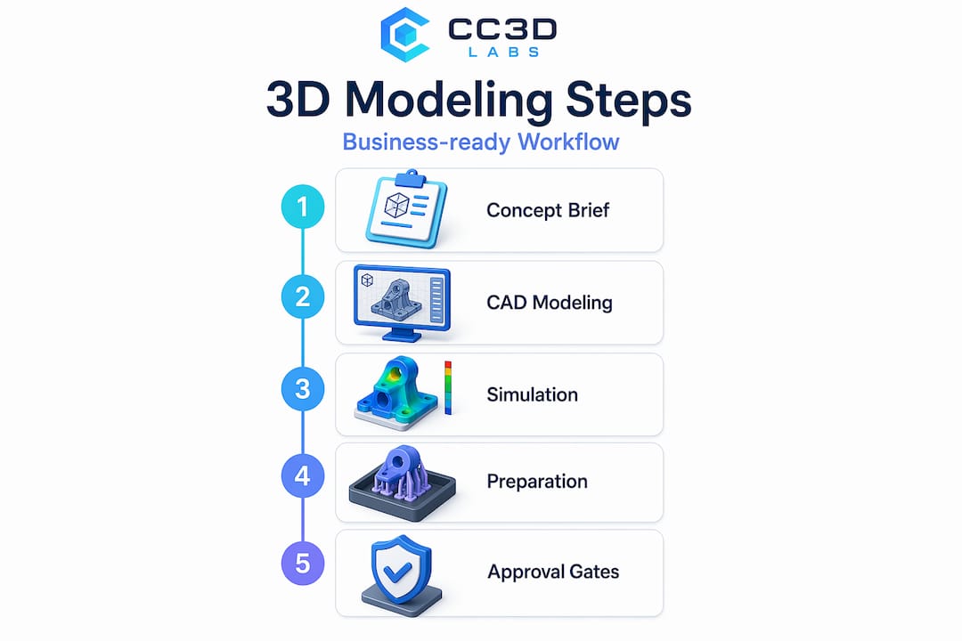
Every reliable product development cycle runs on a defined sequence of stages. The business-ready 3D modeling workflow follows this structure: Concept and brief, CAD geometry design, CAE (computer-aided engineering) simulation and validation, CAM (computer-aided manufacturing) planning, then manufacturing with ERP cost tracking. Product lifecycle management (PLM) sits above all of it as the system of record, connecting every tool and every team.
Without PLM as the connective layer, these stages operate in silos. A CAD designer updates a wall thickness. The CAE analyst runs stress simulations on the old version. The CAM programmer generates toolpaths from a model that no longer exists. That chain of disconnected handoffs is where most manufacturing delays originate.
The five core stages at a glance:
| Stage | Tool | Primary output |
|---|---|---|
| Concept and brief | Requirements docs, sketches | Design intent and constraints |
| CAD geometry design | SOLIDWORKS, Fusion 360, Creo | Solid 3D model files |
| CAE validation | ANSYS, Nastran, SimScale | Simulation reports |
| CAM planning | Mastercam, HSMWorks | Toolpaths and G-code |
| Manufacturing and cost tracking | ERP, PLM | Production records and BOM |
Approval gates between each stage are not bureaucratic overhead. They are cost-control mechanisms. A model that fails CAE validation should never reach CAM programming. Enforcing that boundary through PLM approval workflows eliminates the most expensive class of rework: discovering structural problems after tooling has already been produced.
For businesses scaling toward production, reading a manufacturing-grade 3D printing guide alongside this workflow will clarify how design decisions upstream affect print quality and production yield downstream.
Preparing 3D models for manufacturing: ensuring geometry validity and quality
A valid workflow means nothing if the geometry inside your models is broken. Before any model reaches slicing software or a CNC controller, it must pass two geometric tests: it must be watertight and it must be manifold.

Watertight means the model has no holes or gaps in its surface. Think of it as a sealed container. If you filled it with water, nothing would leak. Manifold means every edge in the mesh is shared by exactly two faces and no more. These are not cosmetic requirements. A model that fails either condition causes slicer failures including missing layers or infinite calculation loops, because the slicing software cannot determine where the inside of the object begins and ends.
Non-manifold edges and open shells create ambiguous topology, which forces slicers into undefined states. The practical consequences range from incomplete prints to parts with internal voids that only reveal themselves under load testing.
Common geometry problems that cause manufacturing failures:
- Open shells and gaps at seams between joined bodies
- Non-manifold edges where three or more faces share one edge
- Inverted surface normals pointing inward instead of outward
- Self-intersecting faces that overlap within the mesh
- Zero-thickness walls generated from Boolean subtractions
- Duplicate faces at assembly join points
The best time to catch these issues is immediately after modeling, before texturing, rigging, or any downstream processing. Run automated mesh analysis using tools built into your CAD platform or dedicated repair software. Then manually inspect high-risk areas like Boolean unions, imported geometry from external sources, and complex joint intersections.
Pro Tip: Boolean operations (cutting one solid from another) are the single most common source of non-manifold geometry in mechanical CAD. After every Boolean, run a quick geometry check before moving forward. It takes 30 seconds and saves hours.
For a structured approach to validating 3D designs for manufacturing or guidance on designing reliable 3D prints from the ground up, those resources will take you deeper into the practical side of geometry quality.
Choosing the right CAD file formats for your 3D modeling process
Geometry validity matters. File format selection matters just as much, and most businesses get this wrong until a manufacturer sends their file back with a rejection notice.
The two formats you will encounter most often are STEP and STL. They are not interchangeable. STEP files carry full solid geometry and are the preferred format for CNC machining because CAM software needs parametric surface data to generate accurate toolpaths. STL files describe geometry as a mesh of triangles, which is exactly what 3D printing slicers need but is fundamentally incompatible with CNC workflows.
STEP vs. STL: when to use each
| Property | STEP | STL |
|---|---|---|
| Geometry type | Solid (B-rep) | Triangle mesh |
| Best use case | CNC machining, injection molding | FDM, SLA, SLS 3D printing |
| Carries tolerances | Yes | No |
| CAM software support | Universal | Limited |
| File size | Larger | Compact |
Export best practices to follow every time:
- Confirm your model is in the correct unit system (millimeters for most manufacturing) before exporting.
- Export individual parts rather than full assemblies unless the manufacturer has explicitly requested an assembly file.
- Set STEP export options to AP214 or AP242 for maximum compatibility with downstream CAM systems.
- For STL exports, increase the triangle resolution (chord height and angular deviation settings) to reduce faceting on curved surfaces.
- Open the exported file in a separate viewer to confirm it looks correct before sending it to a manufacturer.
Pro Tip: Always export a fresh STEP file directly from your finalized CAD model. Never send a STEP that was converted from an STL. That conversion path destroys solid geometry data and produces triangle-mesh pseudo-solids that most CAM software handles poorly.
Understanding the full landscape of CAD file formats for 3D printing is worth the time investment if your team is managing multiple manufacturing processes simultaneously.
Managing 3D model iterations and approvals with PDM workflows
Version control for 3D models is where most small and mid-size manufacturing teams fall behind. Emailing CAD files back and forth, saving versions as “final_v3_REAL_USE_THIS.sldprt,” and losing track of which drawing revision matches which physical prototype are all symptoms of a missing product data management (PDM) system.
SOLIDWORKS PDM tracks design file states, transitions between states, complete version histories, and access permissions. A typical PDM workflow assigns models to states like “In Work,” “Pending Approval,” and “Released.” Transitions between states (like “Submit for Approval” or “Request Change”) require explicit action and generate an audit trail. No one can accidentally overwrite a released drawing.
What a healthy PDM workflow gives your team:
- A single source of truth for every file revision
- Clear accountability for who approved which version and when
- Automatic notifications when a file moves to a new state
- Controlled access so machinists see only released drawings
- Rollback capability if a new revision introduces problems
The efficiency gain from PDM is not just organizational. When a design change is made, PDM flags every file that references the modified part, preventing the scenario where a downstream assembly still references the old geometry. That kind of associativity awareness alone eliminates a significant category of rework.
Keep PDM workflows lean. Four to six states are usually enough for a manufacturing business. Overly complex workflows with a dozen transition rules create friction and encourage teams to work around the system entirely.
For a broader look at how file management fits into the 3D modeling workflow, that guide connects the dots between individual modeling decisions and team-wide processes.
Validating and troubleshooting your 3D models before manufacturing
Running geometry checks during modeling is good practice. Running a formal validation pass before releasing a file to manufacturing is non-negotiable.
Topology validation should function as a release gate, blocking files that fail manifold or watertight checks from reaching slicing or machining workflows. That is not an opinion. It is the only approach that prevents bad geometry from causing tool crashes, failed prints, or scrapped parts.
Recommended validation sequence:
- Import the model into a validation tool or use your CAD platform’s built-in diagnostics immediately after finalizing geometry.
- Run an automated mesh analysis to flag non-manifold edges, open shells, and self-intersections.
- Check surface normals. Inverted normals cause inside surfaces to read as outside surfaces in slicers.
- Inspect wall thickness across the entire model and compare against the minimum wall requirements for your chosen manufacturing process.
- If errors are detected, repair them in the source CAD file and re-export. Never patch errors only in the exported mesh.
- Run the validation sequence again after repair. One fix can expose adjacent problems.
Most common errors found at validation:
- Non-manifold edges at Boolean operation seams
- Open shells from imported geometry fragments
- Inverted normals on mirrored bodies
- Self-intersecting faces from lofts or sweeps with tight radii
- Zero-thickness walls from coincident face pairs
Validation pipelines that automatically detect and attempt repairs prevent invalid geometry from ever reaching manufacturing. Investing in that automation, even in a simple form, pays for itself on the first avoided print failure.
“Skipping pre-manufacturing validation is the single most predictable cause of prototype delays. The geometry problems were always there. You just chose the most expensive moment to find them.”
For teams aiming for tight tolerances and repeatable results, the 3D print accuracy guide covers the downstream side of what validation protects.
Why integrated PLM workflows are the game-changer for 3D modeling efficiency
Here is what most articles on this topic avoid saying: the individual best practices covered above, geometry checks, file format selection, PDM workflows, only work reliably when they are connected by a system that enforces sequence and propagates change automatically.
The biggest efficiency struggle in 3D modeling is not bad geometry or wrong file formats. It is disconnected handoffs. A CAD team working in isolation from their CAE colleagues will generate structurally valid-looking models that fail simulation. A CAM team working from a stale STEP file will produce toolpaths for a geometry that no longer reflects the approved design. PLM eliminates both failure modes by ensuring every team works from the same design truth, and that every change to the master model propagates automatically to all downstream consumers.
The advantage most businesses miss is that PLM enables parallel workflows rather than sequential ones. CAE stress analysis and CAM toolpath generation can run simultaneously on the same approved model, cutting development time significantly. Sequential handoffs, where CAM waits for CAE to finish, double the schedule risk.
Associativity is the key word here. Every downstream artifact, simulation setup, toolpath, drawing, BOM line, must be associatively linked to the master CAD geometry. When the geometry changes, everything updates. When it does not update, you get what most teams call “mystery failures”: manufactured parts that do not match drawings that do not match the model everyone approved.
The businesses that see the most from 3D modeling investment are not the ones with the most powerful CAD software. They are the ones with disciplined, integrated workflows that treat geometry as a single source of truth rather than a file that gets emailed around. Adopting that mindset, even at the small business level, is what separates teams that prototype once from teams that prototype six times before getting it right.
For practical guidance on making this work at lower production volumes, the low-volume manufacturing tips resource covers how to scale these principles without enterprise-level tooling budgets.
Explore professional 3D modeling and printing services to accelerate your product development
When internal resources become a bottleneck, working with a professional 3D modeling and printing partner can close the gap between design intent and physical prototype faster than most teams expect.

CC 3D Labs, based near Philadelphia, provides 3D printing services and metrology-grade 3D scanning for design accuracy that integrate directly into manufacturing workflows. Whether your team needs a validated CAD model turned into a functional prototype, a batch of production parts, or scan data from an existing component to reverse engineer, CC 3D Labs delivers with fast turnaround and the geometry precision that manufacturing demands. Explore the full range of 3D printing prototypes and parts to see what is possible for your next product development cycle.
Frequently asked questions
What is the role of PLM in the 3D modeling process for businesses?
PLM integrates CAD, CAE, CAM, and ERP tools by managing design versions and approval gates, ensuring all teams work from the same updated models to prevent errors and costly rework. As the system of record above all tools, PLM enforces consistent design truth and controls when models move between workflow stages.
Why must 3D models be watertight and manifold before printing?
Watertight and manifold geometry ensures 3D printers can unambiguously define the object’s volume to generate correct toolpaths. Non-manifold edges cause slicers to fail by producing incorrect toolpaths or entering infinite processing loops.
Which CAD file format is best for CNC machining?
STEP files are the best choice for CNC machining because they contain full solid geometry and are widely supported by CAM systems. STL is mesh-based and suited for 3D printing only, making it incompatible with accurate CNC toolpath generation.
How do PDM workflows improve 3D model management in teams?
PDM systems manage design file states, track versions, and control access with clear workflows like “Submit for Approval” and “Request Change,” reducing confusion and ensuring design integrity. SOLIDWORKS PDM tracks file states and transitions, giving teams a reliable audit trail for every revision.
What are common issues caught during 3D model validation before manufacturing?
Validation detects non-manifold edges, open shells, inverted normals, and self-intersections, all of which cause failures in slicing, machining, or assembly simulations if not fixed early. Validation pipelines catch topology issues automatically, preventing invalid geometry from reaching manufacturing and triggering costly downstream failures.