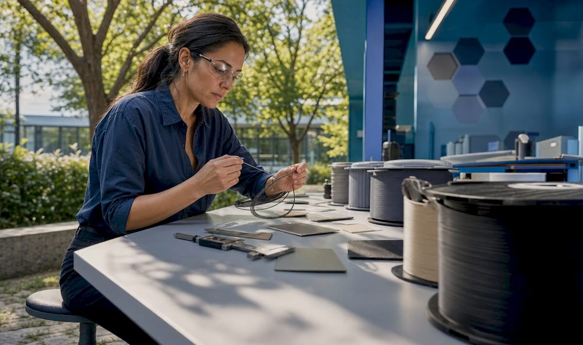
Technician inspecting 3D-printed polymer prototype

Why Use Additive Materials in Manufacturing and Prototyping

Additive manufacturing materials are the substances, ranging from engineering polymers and metal powders to ceramics and fiber-reinforced composites, that 3D printers deposit layer by layer to build a finished part directly from a digital file. The core case for using them is straightforward: the U.S. Department of Energy reports that additive manufacturing can reduce energy use significantly and lower material and waste costs substantially compared to traditional methods. That combination of efficiency and design freedom is why engineers, product developers, and manufacturers across the country are shifting to additive processes for everything from aerospace brackets to medical implants.

The five main material categories are:

  • Polymers (PLA, ABS, PETG, nylon, TPU): the most widely used group, covering prototypes and functional end-use parts
  • Metal powders and wires (titanium, stainless steel, Inconel, aluminum alloys): for structural, high-temperature, and load-bearing applications
  • Composites (carbon fiber or glass fiber reinforced polymers): higher stiffness and strength-to-weight ratios than base polymers alone
  • Ceramics (alumina, zirconia): suited for heat shields, dental restorations, and electronic substrates
  • Sand and binder-jetting materials: used primarily for casting molds and cores in foundry applications

Industry bodies including ASTM International and ISO/TC 261 publish the standards that govern how these materials are tested and qualified for production use.

What types of additive manufacturing materials are available?

Understanding the material options is the first step toward choosing the right one for a given application. Each category has a distinct performance profile, and picking the wrong one wastes both time and money.

Material Typical strength Flexibility Relative cost Common applications
Polymers (PLA/ABS) Low–medium Medium–high Low Prototypes, housings, jigs
Engineering polymers (nylon, PEEK) Medium–high Low–medium Medium Functional parts, brackets
Metal powders (Ti, SS, Inconel) High Low High Aerospace, medical implants
Composites (CFRP) Very high Low Medium–high Structural, motorsport parts
Ceramics High (brittle) Very low High Heat shields, dental, electronics
Sand/binder-jet N/A N/A Low–medium Casting molds and cores

Overhead view of polymers comparison table on table

Polymers dominate prototyping because they are inexpensive, easy to process, and available in a wide range of mechanical properties. Flexible grades like TPU handle living hinges and gaskets; rigid engineering grades like PEEK withstand continuous service above 200°C.

Metal powders unlock the full potential of additive processes for industrial parts. Powder bed fusion (PBF) and directed energy deposition (DED) can produce titanium or Inconel components with internal lattice structures and cooling channels that no subtractive process could replicate. The trade-off is cost: metal feedstock and machine time are expensive, which pushes metal AM toward low-volume, high-value parts.

Composites bridge the gap between polymer accessibility and metal performance. Continuous carbon fiber reinforcement, deposited alongside a nylon or PETG matrix, can produce parts that rival aluminum in stiffness at a fraction of the weight. Aerospace and motorsport teams have adopted this approach for brackets, ducts, and structural panels.

Ceramics and sand occupy specialized niches. Ceramic AM produces dental crowns and heat-resistant components with geometries impossible to achieve by traditional pressing or slip casting. Sand binder jetting prints mold cavities overnight that would take a pattern shop days to machine, compressing foundry lead times dramatically.
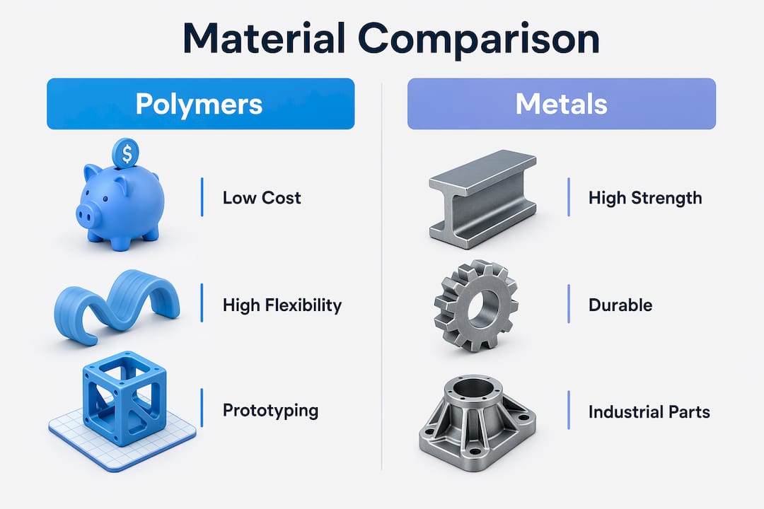
Infographic showing polymers versus metals comparison in additive manufacturing

Pro Tip: When selecting a material, start with the end-use environment, not the printer. A part that must survive 150°C and chemical exposure needs PEEK or a metal, not PLA, regardless of how convenient PLA is to print.

Why use additive materials? The core advantages

The benefits of additive materials in manufacturing go well beyond “you can print complex shapes.” Each advantage connects to a measurable outcome in cost, time, or performance.

Design freedom that traditional processes cannot match

Additive processes build geometry by addition, so internal channels, lattice infill, and organic topology-optimized shapes are no harder to produce than a solid block. Topology optimization, which uses software to remove material from low-stress regions while preserving load paths, can reduce part weight substantially across multiple industries according to comparative lifecycle studies. Lighter parts mean lower fuel consumption in aerospace and automotive applications, which creates environmental and operating-cost benefits that extend well beyond the factory floor. You can read more about how design-for-manufacturing principles apply to this in Cc3dlabs’s guide on DFM in 3D printing.
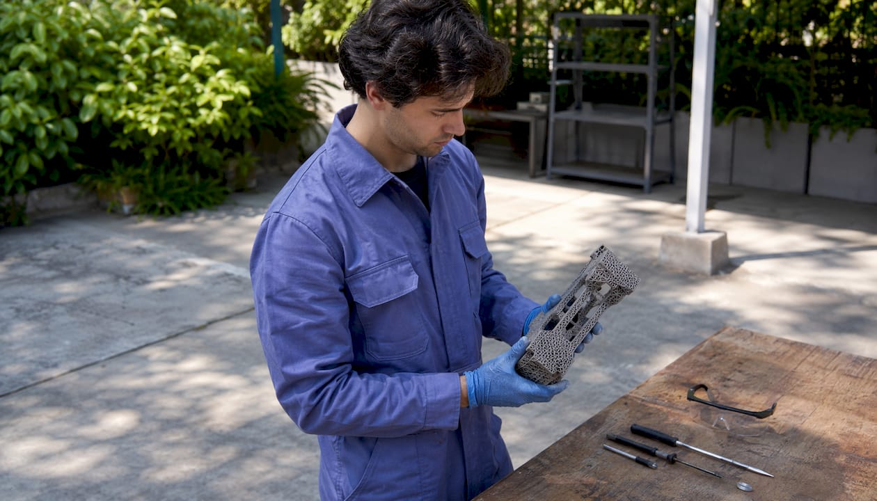
Engineer inspecting complex 3D printed aerospace part

Material efficiency that subtractive methods cannot approach

Subtractive manufacturing such as CNC milling can waste a large majority of the starting billet, particularly in aerospace applications where titanium billets are machined down to thin-walled brackets. Additive processes typically achieve high material utilization rates, depositing material only where the geometry requires it. That gap in buy-to-fly ratio is one of the clearest economic arguments for additive materials when feedstock is expensive.

Tooling cost elimination for low-volume production

Traditional injection molding or die casting requires hard tooling that can exceed 80% of total production costs for a given part. Additive manufacturing skips that step entirely. No mold, no die, no fixture. For production runs below roughly 1,000 parts per year, this makes additive the cost-effective choice in most geometries. Aerospace, medical, defense, and energy sectors recognized this early because they routinely produce high-mix, low-volume parts where tooling amortization would be prohibitive.

Supply chain simplification through localized production

Localized additive manufacturing reduces dependence on distant suppliers by enabling on-demand production close to the point of use. Instead of warehousing thousands of spare parts, a facility can store digital files and print what it needs when it needs it. That shift cuts inventory carrying costs and reduces the risk of supply disruption, a lesson that became painfully clear to many U.S. manufacturers during recent global logistics crises.

Sustainability advantages at the right production scale

  • Additive processes generate less scrap than subtractive methods, reducing raw material extraction and disposal burdens.
  • Eliminating tooling removes the energy and emissions embedded in mold manufacturing.
  • Lighter parts produced through topology optimization reduce fuel consumption during a product’s service life.
  • AM has lower environmental impacts than traditional manufacturing when production volumes are low or part geometry would cause high material waste conventionally.

Key figure: The U.S. Department of Energy reports additive manufacturing can cut waste and material costs by up to 90% compared to traditional production.

What is driving the development and adoption of additive materials?

The growth of additive materials is not happening in a vacuum. Several converging forces are pushing manufacturers, product developers, and researchers to invest in this technology.

  • Demand for customization. Consumer and industrial markets increasingly expect products tailored to specific users or operating conditions. Additive materials make one-off or small-batch customization economically viable without the penalty of tooling costs.
  • Rapid prototyping pressure. Shortening development cycles is a competitive necessity. Additive processes compress the time from CAD file to physical part from weeks to hours, letting engineering teams iterate faster and catch design flaws earlier.
  • Advances in printer capability. Multi-material printers, higher-temperature build chambers, and in-situ monitoring systems have expanded the range of materials that can be processed reliably. Machine learning and digital twins are now accelerating process stabilization and reducing qualification lead times.
  • Lightweighting requirements in aerospace and automotive. Electrification of vehicles increases the premium on structural weight reduction because battery mass must be offset elsewhere. Additive materials, combined with topology optimization, deliver weight savings that material substitution alone cannot achieve.
  • Regulatory and sustainability pressure. U.S. and international regulations on emissions and waste are pushing manufacturers toward processes that use less material and generate less scrap. Additive materials align with those goals at appropriate production scales.
  • Declining system and material costs. Between 2001 and 2011, the average price of additive manufacturing systems fell 51% after adjusting for inflation. That trend has continued, broadening access beyond aerospace and defense to mid-market manufacturers and startups.

The industries that adopted additive materials earliest, aerospace, medical, and defense, share a common profile: high part complexity, low production volumes, and high material value. Automotive and heavy transportation followed as lightweighting needs intensified. Dental and jewelry sectors adopted additive processes because personalization commands a price premium that justifies the per-unit cost. Each new sector that crosses over expands the material ecosystem and drives further cost reductions.

Research findings and U.S. industrial examples that show real-world impact

The performance claims around additive materials are well-documented, but the nuances matter as much as the headline numbers.

Energy and waste savings: what the data actually shows

The U.S. Department of Energy’s figures, up to 25% energy reduction and up to 90% material cost savings, represent the upper bound of what is achievable under favorable conditions. Those conditions are low production volume, complex part geometry, and expensive feedstock. A systematic review of comparative lifecycle studies found that AM has lower environmental impacts than traditional manufacturing when annual production volumes stay below approximately 1,000 parts, or when the part geometry would generate high material waste if machined conventionally. At higher volumes, the calculus flips: slow build rates and energy-intensive feedstock production can make additive processes less efficient than injection molding or stamping.

Industrial case study: on-site maintenance manufacturing

An industrial maintenance application documented by Kennametal demonstrated what on-site additive manufacturing can deliver in practice. Producing replacement parts additively rather than through traditional machining and forging reduced part weight by 50% and cut emissions by 45%. Those results came from combining topology-optimized designs with metal AM, exactly the kind of geometry-plus-process pairing that makes additive materials most effective.

The hidden costs engineers need to account for

Additive manufacturing carries costs that do not show up in a simple part-weight comparison. Feedstock production and post-processing are both energy-intensive and can significantly increase the environmental footprint of an additively manufactured part. Metal powder atomization, support structure removal, heat treatment, and surface finishing all add time, labor, and energy. Studies that omit these steps from their scope tend to overstate the sustainability advantage of additive processes. A complete cradle-to-gate analysis, covering feedstock, build phase, and post-processing, is the only reliable way to compare additive and traditional routes.

Design knowledge as a prerequisite

Realizing the full benefits of additive materials requires topology optimization and design-for-AM approaches that most engineers trained on subtractive processes have not yet internalized. Internal lattice structures, self-supporting geometries, and integrated cooling channels are not default outputs of conventional CAD workflows. Organizations that invest in this design knowledge consistently outperform those that simply substitute additive for subtractive without redesigning the part. Cc3dlabs’s manufacturing-grade 3D printing guide covers how these design principles translate into production-ready parts.

The honest picture of additive materials is one of genuine, well-documented advantages bounded by real constraints. The technology is not universally superior to traditional manufacturing. It is specifically superior for complex geometries, low volumes, expensive materials, and applications where design freedom creates downstream performance gains. Understanding where those boundaries sit is what separates engineers who get results from those who get expensive prototypes.


Key Takeaways

Additive manufacturing materials deliver their greatest advantages at low production volumes, with complex geometries, and when design freedom is used to reduce weight and eliminate tooling costs.

Point Details
Material utilization advantage Additive processes achieve utilization rates above 90%; subtractive methods can waste up to 90% of starting material.
Energy and cost savings The U.S. Department of Energy reports up to 25% energy reduction and up to 90% material cost savings versus traditional methods.
Tooling cost elimination Tooling can exceed 80% of total production costs in injection molding; additive manufacturing removes that expense entirely.
Optimal production volume AM is most cost-effective and environmentally favorable at roughly 1,000 parts per year or fewer, or for high-waste geometries.
Hidden costs require full analysis Feedstock production and post-processing are energy-intensive; a complete lifecycle assessment is needed for accurate comparison.

Put additive materials to work for your next project

https://cc3dlabs.com

Cc3dlabs operates near Philadelphia and specializes in filament-based 3D printing, multi-material production, and professional handheld 3D scanning (accuracy to ~0.1 mm) for businesses, product developers, and engineers across the U.S. Whether you need a single functional prototype or a batch of production parts, the team works from your CAD file to a finished, inspected part with fast turnaround. Explore the full range of professional 3D printing services or get a free online estimate to see what additive materials can do for your specific application.
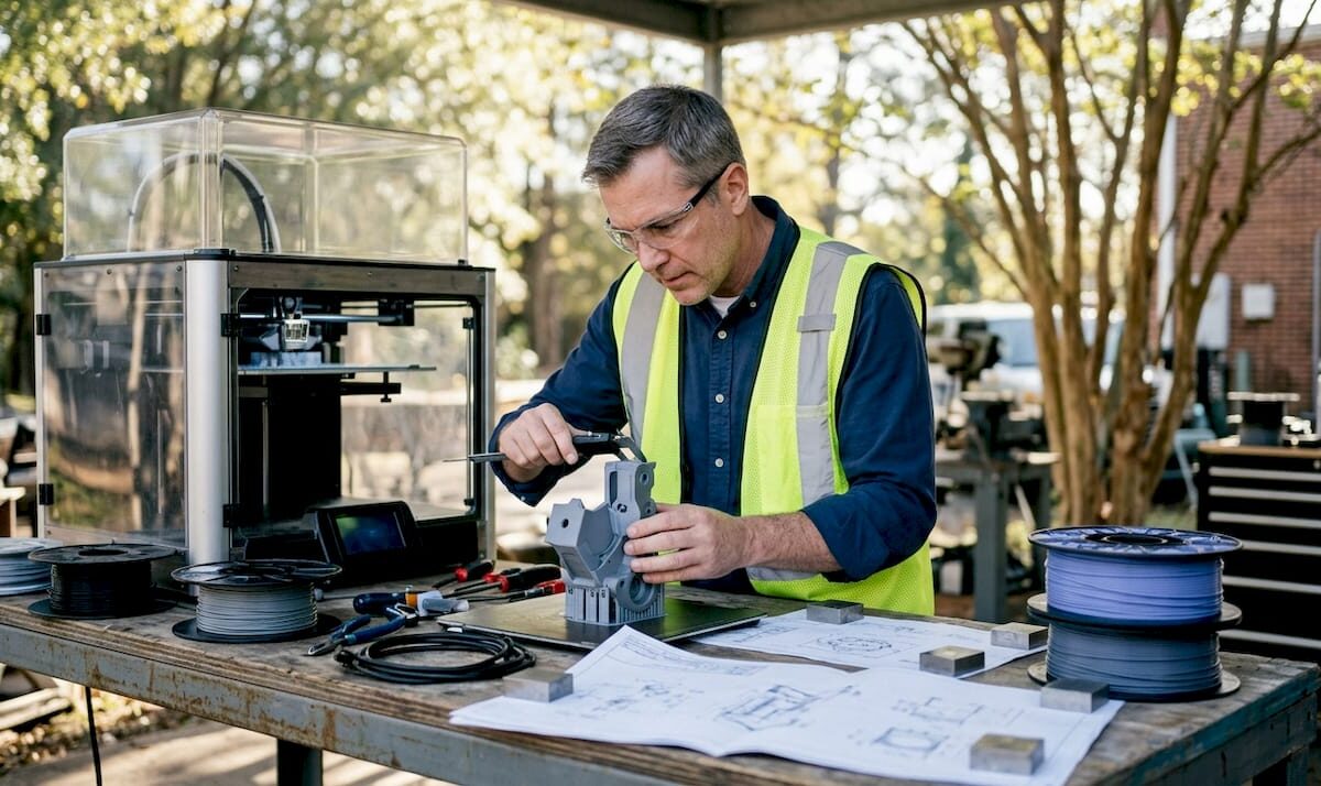
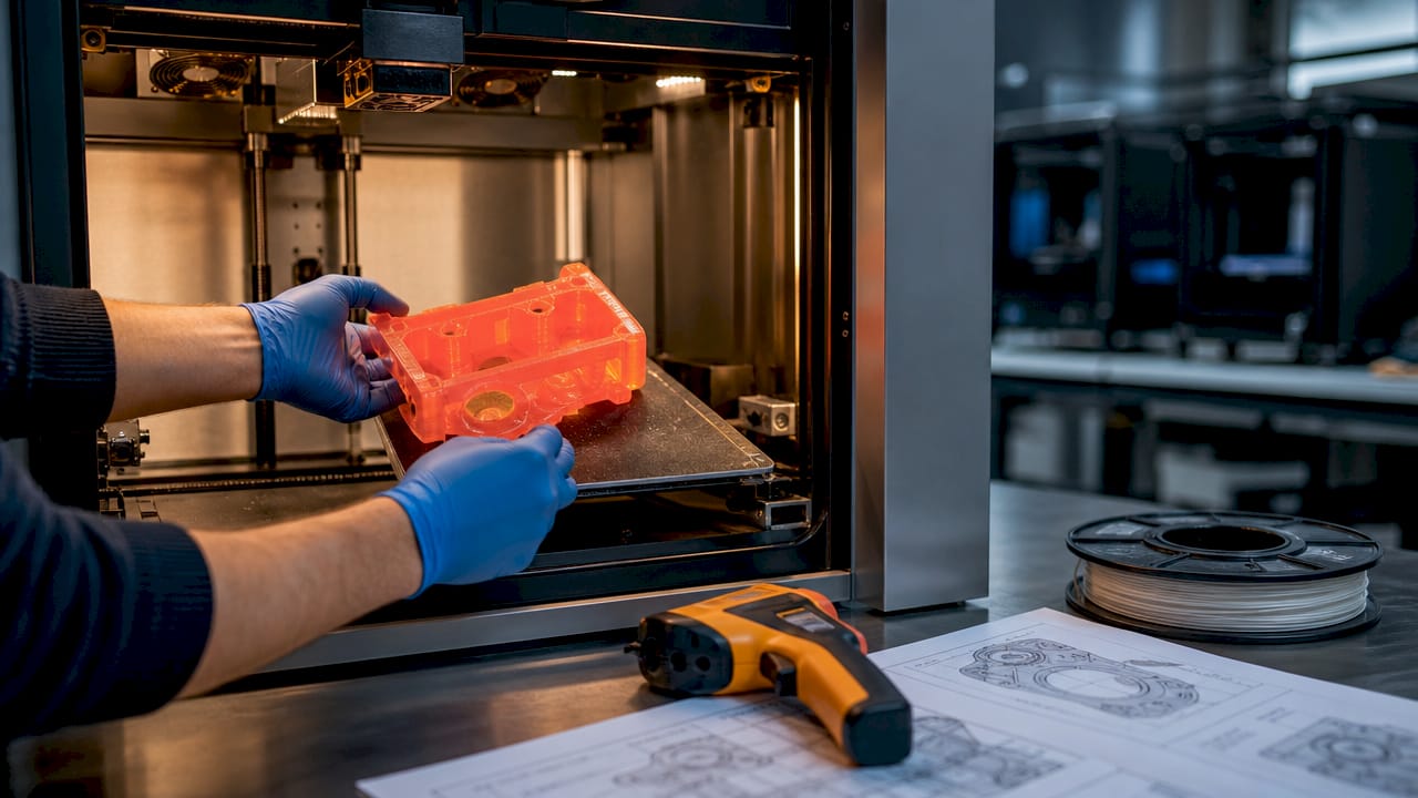
Engineer inspecting 3D-printed high-temp filament part

Why Use High-Temp Filaments for Engineering-Grade Parts


TL;DR:

  • High-temp filaments can withstand continuous service temperatures above 150°C and resist chemicals and flames. They enable durable parts in aerospace, automotive, and medical sectors where high thermal and chemical resistance are essential. Proper hardware, including hotends and heated chambers, is necessary for successful printing with these advanced materials.

High-temp filaments are 3D printing materials engineered to maintain structural integrity at continuous service temperatures above 150°C, far beyond what standard PLA or ABS can handle. The industry term for this material class is “high-performance engineering thermoplastics,” and understanding why use high-temp filaments starts with one fact: standard filaments fail where these materials thrive. PLA deflects at roughly 60°C. ABS holds up past 100°C. But the moment you need a part that survives an engine bay, an autoclave, or a chemical processing line, you need a different class of material entirely. Heat Deflection Temperature (HDT) is the key metric that separates these tiers, and it drives every material decision in this space.

What are the main benefits of using high-temperature filaments?

High-temp filaments deliver four core advantages that standard materials cannot match: thermal stability, mechanical strength, chemical resistance, and flame retardancy. Each one matters in a different way depending on your application.

Hands removing hot 3D-printed polycarbonate part

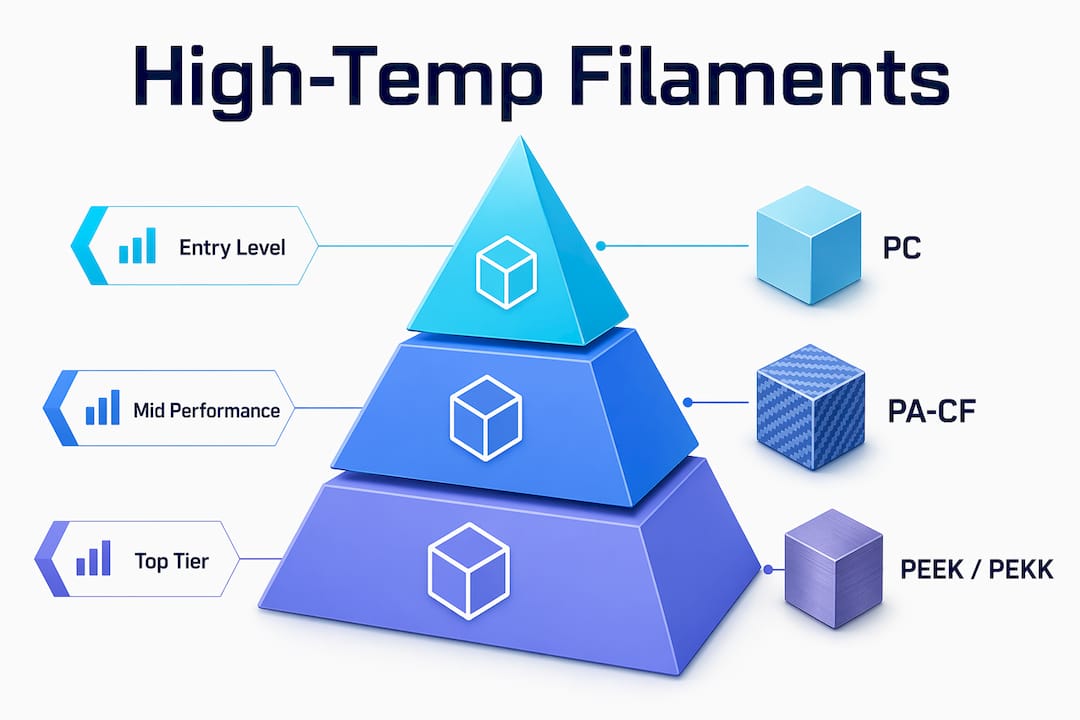
Thermal stability is the most obvious benefit. Parts printed in polycarbonate (PC) hold their shape up to approximately 140°C HDT. Nylon composites like PA-CF push that threshold to 150–180°C. PEI (also marketed as ULTEM) exceeds 200°C, and PEEK or PEKK top out above 250°C. That range covers nearly every industrial thermal environment outside of direct flame contact.

Mechanical performance is where these materials separate themselves from consumer filaments. High-temp thermoplastics offer high impact strength, tensile strength, and fatigue resistance. A PA-CF bracket on a vibrating assembly line will outlast a PLA version by orders of magnitude. The fiber reinforcement in carbon-filled nylon composites also improves stiffness without adding significant weight.

Infographic ranking high-temp filament materials by performance

Chemical resistance is critical for fluid-contact applications. High-temp filaments resist automotive fluids, fuels, oils, acids, and industrial cleaning agents. A standard ABS part submerged in brake fluid will swell and crack. A PEEK part will not.

Flame retardancy adds a compliance dimension. PEI carries a UL 94 V-0 flame rating, which is the highest classification for self-extinguishing plastics. That rating matters directly for aerospace interiors, medical enclosures, and consumer electronics housings where fire safety standards are non-negotiable.

  • Superior heat resistance prevents deformation in hot environments
  • High tensile and impact strength for load-bearing functional parts
  • Chemical resistance to fuels, oils, acids, and solvents
  • UL 94 V-0 flame retardancy in select materials like PEI
  • Long service life for tooling, fixtures, and end-use components

Pro Tip: When evaluating a high-temp filament for a new application, check both the HDT and the continuous service temperature. HDT is measured under load for a short period. Continuous service temperature reflects long-term real-world performance, and the gap between the two can be significant.

Which industries and applications benefit most from high-temp filaments?

High-temp filaments open possibilities for durable, functional parts in roles previously limited to metals, enabling weight savings and corrosion resistance across multiple sectors. The industries below represent the highest-value use cases.

  • Aerospace: PEI is certified to FAR 25.853 for aircraft interior components, covering flame, smoke, and toxicity requirements. PEEK is used for structural brackets and ducting where metal replacement saves meaningful weight.
  • Automotive: Parts near engines, exhaust systems, or fluid reservoirs require both thermal and chemical resistance. PA-CF and PEI handle these environments reliably, and 3D printing allows rapid iteration on bracket and housing geometry.
  • Medical devices: PEI and PEEK are biocompatible and withstand repeated steam sterilization in autoclaves. PEEK’s mechanical properties rival some metals, making it suitable for surgical guides, implant trials, and instrument housings.
  • Industrial tooling and fixtures: Jigs, clamps, and assembly fixtures printed in PC or PA-CF endure prolonged mechanical stress and elevated temperatures on factory floors without creeping or deforming.
  • Consumer electronics: Enclosures for power electronics, motor controllers, and battery management systems benefit from the flame retardancy and dimensional stability of PEI and PC.

The common thread across all these sectors is that the part must perform reliably under conditions that would degrade a standard filament within hours. For engineers and product developers who need to choose filaments for engineering parts, the application environment is the starting point for every material decision.

What hardware do you need to print high-temp filaments?

Printing high-temp filaments requires hardware that most consumer desktop printers cannot provide. The gap between a standard FDM machine and an industrial-grade system is not a minor calibration issue. It is a fundamental equipment difference.

  1. All-metal hotend: Standard PTFE-lined hotends degrade above 260°C, releasing toxic fumes and contaminating prints. An all-metal hotend is mandatory for materials like PEEK and PEI that require extrusion temperatures of 300°C or higher. This is a non-negotiable hardware upgrade, not an optional accessory.

  2. Actively heated print chamber: A passive enclosure slows heat loss but does not maintain a stable ambient temperature. An actively heated chamber prevents warping by keeping the part at a controlled temperature throughout the print. Without it, semi-crystalline polymers like PEEK suffer delamination and brittleness as layers cool unevenly.

  3. High-temperature heated build plate: Bed temperatures of 100°C or higher are required for adhesion with most high-temp materials. PC typically needs 110–120°C. PEEK may require 160°C or more. A standard 60°C bed will not hold these parts.

  4. Filament dryer or dry storage: Moisture absorption in nylon-based filaments causes steam bubbles during extrusion, producing brittle, porous parts. Drying PA-CF at 80–90°C for 8–12 hours before printing is standard practice, not optional preparation.

  5. Rigid, thermally stable frame: High chamber temperatures cause thermal expansion in printer frames. Industrial machines use aluminum or steel frames designed to maintain dimensional accuracy at elevated ambient temperatures.

Pro Tip: If you are printing PA-CF or PEI for the first time, run a filament drying cycle even on a freshly opened spool. Moisture absorbs during shipping and storage, and a single wet print can ruin an expensive spool and a long print job.

The printer setup requirements for high-temp materials are well-documented, but engineers frequently underestimate how much the chamber environment affects final part quality. Active heating is the single most impactful upgrade after the hotend.

How do different high-temp filament types compare?

Not all high-temp filaments are equal in performance, processability, or cost. The right choice depends on your thermal target, mechanical requirements, and available hardware.

Polycarbonate (PC) is the entry point for high-temp printing. It offers an HDT of approximately 140°C and good impact resistance, and it bridges the gap between consumer and engineering filament tiers. PC teaches you the fundamentals of high-temp printing without requiring a full industrial machine.

PA-CF (carbon fiber reinforced nylon) pushes thermal performance to 150–180°C while adding stiffness and strength from the carbon fiber fill. The trade-off is hygroscopicity. Nylon absorbs moisture aggressively, and PA-CF parts must be dried before and during printing to maintain quality.

PEI (ULTEM) is the aerospace and medical workhorse. Its amorphous polymer structure gives it dimensional stability and easier printing than semi-crystalline alternatives. The UL 94 V-0 rating and FAR 25.853 certification make it the default choice for regulated industries.

PEEK and PEKK represent the top tier. PEEK has an HDT exceeding 250°C and mechanical properties that rival some metals. It requires controlled slow cooling in a heated chamber to develop the optimal crystalline structure. The hardware cost is high, and the process window is narrow, but no other printable polymer matches its performance ceiling.

Material HDT Key Strength Main Challenge
Polycarbonate (PC) ~140°C Impact resistance, accessible Moisture sensitivity, warping
PA-CF (Nylon CF) 150–180°C Stiffness, strength-to-weight Highly hygroscopic, needs drying
PEI (ULTEM) 200°C+ Flame retardancy, certifications High print temp, material cost
PEEK / PEKK 250°C+ Near-metal strength, biocompatible Expensive hardware, narrow process window

For engineers exploring advanced filament materials, the table above is a starting framework. Real-world selection requires testing under actual service conditions, not just comparing spec sheets.

Key takeaways

High-temp filaments are the correct material choice when a part must survive temperatures above 140°C, contact with chemicals, or regulated flame-retardancy requirements.

Point Details
HDT defines material selection Match the filament’s HDT to your application’s peak operating temperature, not average temperature.
Hardware is non-negotiable All-metal hotends and actively heated chambers are required, not optional, for PEEK and PEI.
Moisture ruins expensive prints Dry all hygroscopic filaments like PA-CF and PEI before every print run to prevent voids and brittleness.
Start with polycarbonate PC teaches high-temp printing fundamentals at lower hardware cost before advancing to PEEK or PEI.
Certifications drive industry adoption PEI’s UL 94 V-0 and FAR 25.853 ratings make it the default for aerospace and medical applications.

What I’ve learned from printing with high-temp materials

The most common mistake I see engineers make is treating high-temp filament selection as a spec-sheet exercise. They find a material with the right HDT, order a spool, and load it into a machine that was never designed for it. The print fails, they blame the filament, and they walk away thinking PEEK or PEI is not ready for production use.

The hardware foundation is everything. An all-metal hotend and an actively heated chamber are not upgrades you add later. They are prerequisites. I have seen teams spend weeks troubleshooting delamination and warping in PEEK parts before realizing their chamber was passively enclosed, not actively heated. The fix was a hardware change, not a slicer setting.

Moisture management is the second failure point that catches people off guard. Nylon composites absorb humidity fast. I have opened a spool that sat on a shelf for three days and found it wet enough to produce audible popping during extrusion. A dedicated filament dryer running continuously during long print jobs is not excessive. It is standard practice for anyone printing PA-CF or PEI at volume.

My practical advice: start with polycarbonate. It runs at lower temperatures than PEEK or PEI, it teaches you the warping and adhesion behavior of high-temp materials, and it produces genuinely useful parts. Once you have dialed in your hardware and process with PC, the transition to PEI is manageable. PEEK is a different level entirely and deserves its own dedicated machine and process development time.

The payoff for getting this right is real. Once your process is dialed in, high-temp filaments produce parts with repeatability and mechanical performance that justify the investment many times over.

— Justin

Cc3dlabs prints engineering-grade filaments for demanding applications

Engineers and product developers who need functional prototypes or end-use parts in high-temp materials do not always have the hardware or process expertise in-house. CC 3D Labs, based near Philadelphia, operates a professional FDM print farm running engineering-grade filaments including polycarbonate (PC) and carbon-fiber nylon (PA-CF) for prototyping and production runs. Ultra-high-temperature polymers like PEI (ULTEM) and PEEK require industrial systems beyond standard service FDM equipment — if your part truly needs them, we’ll say so up front and point you toward the right process.

https://cc3dlabs.com

The team at Cc3dlabs advises on material selection based on your application’s thermal, mechanical, and regulatory requirements. Whether you need a single prototype or a batch of functional parts, Cc3dlabs provides free online estimates, design support, and fast turnaround with local pickup or shipping. If your part needs to survive heat, chemicals, or a certification audit, Cc3dlabs has the equipment and expertise to print it correctly the first time.

FAQ

What temperature can high-temp filaments withstand?

High-temp filaments cover a wide range: polycarbonate holds up to approximately 140°C HDT, PEI exceeds 200°C, and PEEK surpasses 250°C. The right threshold depends on your application’s peak operating temperature and load conditions.

Why can’t I print PEEK on a standard desktop printer?

Standard PTFE-lined hotends degrade above 260°C and release toxic fumes, making them unsafe for PEEK extrusion temperatures of 370–400°C. PEEK also requires an actively heated chamber to prevent delamination, which most consumer machines do not provide.

Is PEI safe for medical and aerospace applications?

PEI is certified to FAR 25.853 for aircraft interiors and carries a UL 94 V-0 flame rating, making it the standard choice for regulated aerospace and medical applications. Its amorphous structure also gives it better dimensional stability than semi-crystalline alternatives like PEEK.

Do I need to dry high-temp filaments before printing?

Drying is required for all hygroscopic high-temp filaments, particularly nylon composites and PEI. Moisture absorbed during storage causes steam bubbles during extrusion, producing brittle, porous parts that waste expensive material.

When should I use high-temp filaments instead of standard materials?

Use high-temp filaments when your part will face continuous temperatures above 100°C, contact with chemicals or fuels, prolonged mechanical stress, or flame-retardancy compliance requirements. For parts that operate below those thresholds, standard materials like PETG or ABS are sufficient and easier to process.

Engineer inspecting 3D printed object closely

The Role of Layer Adhesion in 3D Prints: A Pro Guide


TL;DR:

  • Layer adhesion in 3D printing depends on polymer fusion and chain entanglement before the interface freezes.
  • Controlling factors such as nozzle temperature, build plate heat, fan speed, and part orientation is essential for optimizing bond strength.

Layer adhesion in 3D printing is defined as the interlayer bond strength formed when successive layers of molten polymer fuse together before the interface freezes. This bond quality is the single most important factor determining whether a printed part behaves as a solid, monolithic object or a laminated stack that splits under load. The role of layer adhesion in 3D prints extends far beyond surface appearance. It governs tensile strength, failure mode, and long-term durability. Understanding interlayer bonding, the industry’s standard term for this phenomenon, is non-negotiable for anyone producing functional parts with FDM or FFF technology.

What factors most influence layer adhesion quality in 3D printing?

Layer adhesion is fundamentally a polymer welding problem. A fresh bead must wet, contact, and fuse with the previous layer while both surfaces remain above the glass transition or crystallization threshold. Once the interface freezes, bond strength plateaus and no amount of downstream heat will recover it.

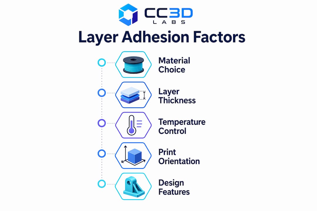
Several variables control whether that fusion window stays open long enough:

  • Nozzle temperature. Higher melt temperatures increase polymer chain mobility and extend the fusion window. Prusa recommends adjusting printing temperature in 5°C increments for PLA to find the adhesion sweet spot without burning the material.
  • Cooling fan speed. Aggressive cooling locks the interface before chains can entangle. For ABS, Prusa explicitly recommends running the fan off entirely and using an enclosure to prevent delamination.
  • Layer thickness. Thinner layers produce stronger bonds. A 2026 Springer study found that PETG loses roughly 50% of shear strength at higher layer thicknesses, while PLA drops about 29%. Thinner layers mean more contact area and longer thermal exposure per unit of height.
  • Build plate temperature. HIPS showed improved interlayer bond quality at approximately 105°C build plate temperature, while PP suffered from warping and voids when plate temperature was mismatched. Molecular diffusion at the interface depends on sustained heat from below.
  • Ambient environment. Drafts and humidity disrupt the thermal profile around the part. Thermal gradients from the bed, enclosure, and environment influence void formation and residual stresses that degrade adhesion beyond nozzle temperature alone.

Pro Tip: Never treat nozzle temperature as the only thermal lever. Build plate temperature, enclosure heat, and fan speed all shape the time-temperature history at the interface. Tune them together, not in isolation.

How does layer adhesion affect mechanical performance and failure modes?

Hands adjusting 3D printer nozzle temperature control

Weak interlayer bonding creates a predictable failure path. Load applied perpendicular to the layer lines generates peel stress at the weld lines, and the part splits along those interfaces rather than through the material itself. This is the defining characteristic of anisotropic behavior in FDM parts: strength along the print axis is always lower than strength within a layer plane.

Mechanical testing reveals how adhesion quality shows up in real failure data:

  1. Tensile testing perpendicular to layers exposes the weakest bond directly. Parts with poor adhesion fracture cleanly at layer interfaces at loads well below the material’s rated tensile strength.
  2. Shear testing measures how well layers resist sliding against each other. Mechanical interlocking between bi-material FDM joints can reach shear strength above 24 MPa, compared to roughly 21.7 MPa for alternate deposition without interlocking geometry.
  3. Bending tests reveal combined tension and compression across layers. Delamination typically initiates on the tension face where peel stress concentrates.
  4. Fracture surface analysis is the most practical diagnostic. A smooth shear fracture indicates good bonding. A rough, stepped fracture surface signals adhesion failure at the interface rather than bulk material failure.
Material Layer thickness effect Approximate strength loss
PLA Increased thickness reduces bond ~29% at higher layer heights
PETG More sensitive to thickness ~50% at higher layer heights
PEKK Crystallization-controlled 93.9 MPa tensile via cooling regulation
HIPS Build plate temperature sensitive Improved at ~105°C plate temp

The table above makes one point clear: material choice and layer thickness interact. You cannot apply PLA settings to PETG and expect equivalent bond quality.

Design decisions compound the risk. Parts oriented so that the primary load runs parallel to layer lines perform far better than parts where load pulls layers apart. For strength-critical parts, print orientation is as important as material selection.

Infographic illustrating key factors of layer adhesion

What advanced techniques and design strategies enhance layer adhesion?

Professional-grade adhesion requires going beyond default slicer presets. The following approaches produce measurable improvements in interlayer bond strength:

  • Mechanical interlocking geometry. When chemical adhesion between two materials is limited, geometry does the work. Dovetail or interlocking features at bi-material interfaces limit interlayer sliding under shear and push shear strength above what surface bonding alone achieves.
  • Extrusion multiplier tuning. Slight over-extrusion (typically 1–5% above nominal) increases contact pressure between the fresh bead and the previous layer. This widens the fusion zone without requiring a temperature increase that might cause stringing or dimensional error.
  • Controlled crystallization for high-performance polymers. PEKK and similar semi-crystalline materials require cooling regulation to stay below the crystallization threshold during printing. Printed PEKK parts achieved tensile strength of 93.9 MPa when cooling was managed to preserve chain mobility. Premature crystallization induces brittleness and kills bond quality.
  • Enclosures for warp-prone materials. ABS, ASA, and PC all benefit from a heated enclosure that keeps the ambient temperature above the material’s glass transition. This extends the fusion window for every layer deposited.
  • Layer orientation strategy. Aligning the print so that critical load paths run parallel to layer planes, not perpendicular to them, avoids peel stress at weld lines entirely. This is a design decision, not a slicer setting, and it belongs in the part design phase.

Pro Tip: When printing multi-material parts, add a small interlocking feature at the interface zone rather than relying on surface contact alone. Even a simple tongue-and-groove profile dramatically increases shear resistance where chemical bonding is limited.

Common challenges with layer adhesion and how to troubleshoot them

Most real-world FDM delamination comes from thermal mismatch and poor interface control, not from defective filament or hardware failure. Knowing what to look for narrows the diagnosis quickly.

  • Visible layer separation or cracking. The first check is always temperature. Raise nozzle temperature in 5°C steps. For ABS, confirm the fan is off and the enclosure is sealed against drafts.
  • Weak fracture along layer lines under light load. This points to insufficient fusion time. Reduce print speed to keep the interface hot longer, or increase nozzle temperature. Check that the wall thickness is adequate for the load the part will carry.
  • Delamination only at specific heights. Look for environmental causes: a nearby vent, a door opening during the print, or a section of the part that cools faster due to geometry. Drafts cause localized thermal drops that freeze interfaces prematurely.
  • Inconsistent bond quality across a batch. Filament moisture is the most common culprit. Wet filament produces steam voids at the interface that destroy bond continuity. Dry filament at the manufacturer’s recommended temperature before printing.
  • Rough fracture surface on a failed part. A rough, granular fracture face confirms adhesion failure rather than bulk material failure. Smooth fracture surfaces indicate the bond held and the material itself failed, which is the correct outcome for a well-printed part.

Thermal profile control is more effective than simply raising temperature across the board. Systematic adjustment of nozzle temperature, bed temperature, fan speed, and enclosure conditions together produces consistent results. Changing one variable at a time makes it possible to identify the actual cause rather than masking it.

Key takeaways

Strong interlayer bonding requires controlling the full thermal environment at the interface, not just the nozzle temperature, and designing parts so critical loads run parallel to layer planes rather than pulling layers apart.

Point Details
Adhesion is a welding problem Polymer chains must entangle before the interface freezes; once frozen, bond strength cannot recover.
Layer thickness drives strength loss PETG loses ~50% shear strength at higher layer thicknesses; thinner layers consistently outperform thicker ones.
Thermal environment matters beyond the nozzle Build plate temperature, enclosures, and draft control all shape the fusion window at every layer.
Mechanical interlocking compensates for weak chemistry Interlocking geometry at bi-material joints pushes shear strength above 24 MPa where surface bonding falls short.
Fracture surface analysis beats visual inspection Rough fracture faces confirm adhesion failure; smooth faces confirm the bond held and material failed correctly.

Why I think most 3D printing teams underestimate thermal environment

The industry conversation about layer adhesion almost always centers on nozzle temperature. Raise it, lower it, find the sweet spot. That framing is too narrow, and I have seen it lead experienced teams in circles for weeks.

The interface does not care only about what temperature the nozzle deposited the material at. It cares about the entire time-temperature history from deposition to freeze. A draft from an HVAC vent three feet away can collapse bond quality on one side of a tall part while the other side prints perfectly. A build plate running 10°C below spec on a HIPS job produces voids that look like filament defects but are actually thermal failures.

What I find most useful is treating the printer as a thermal system, not a mechanical one. Before changing any slicer setting, I look at the fracture surface of a failed part. Rough and stepped means the interface never fused properly. Smooth and planar means the bond held and something else failed. That single observation cuts diagnostic time in half.

The other thing I push hard on is print orientation. Most practitioners treat it as a geometry problem. It is actually a stress engineering problem. Orienting a bracket so the primary load runs along the layer plane instead of across it can double effective part strength without changing a single print parameter. That is free performance, and it costs nothing except a few minutes of thought during prototype design.

Continuous experimentation with materials and parameters is the only way to build real intuition here. No datasheet replaces the knowledge you get from deliberately breaking parts and reading the fracture surfaces.

— Justin

Cc3dlabs delivers prints where layer bonding is never a compromise

https://cc3dlabs.com

At Cc3dlabs, near Philadelphia, every filament-based print goes through a process tuned for the specific material and part geometry. That means build plate temperatures dialed for the polymer, enclosures used where ABS or ASA demand them, and layer thickness selected for the strength the part actually needs. The team handles everything from single prototypes to batch production runs, with material consultation built into the workflow. If you need parts that hold up under real mechanical loads, explore Cc3dlabs’ professional 3D printing services or get a free online estimate to see what optimized layer bonding looks like in practice.

FAQ

What is layer adhesion in 3D printing?

Layer adhesion is the bond formed between successive layers of deposited polymer in FDM or FFF printing. Bond strength depends on polymer chain entanglement and fusion before the interface freezes by glass transition or crystallization.

Why does layer thickness affect interlayer bond strength?

Thinner layers maintain more contact area and longer thermal exposure between the fresh bead and the previous layer. A 2026 Springer study found PETG loses approximately 50% of shear strength at higher layer thicknesses compared to 0.1mm layers.

How do I fix layer separation in ABS prints?

Turn the cooling fan off, use an enclosure to block drafts, and raise nozzle temperature in 5°C increments. Most ABS delamination comes from thermal mismatch and ambient air cooling the interface before fusion completes.

Does print orientation affect layer adhesion performance?

Print orientation determines whether loads run parallel or perpendicular to layer planes. Parts oriented so critical loads run parallel to the layer plane avoid peel stress at weld lines and perform significantly better under mechanical loading.

What does a rough fracture surface on a failed print indicate?

A rough, stepped fracture surface confirms that the interlayer bond failed rather than the bulk material. A smooth fracture surface means the bond held correctly and the material itself reached its strength limit.

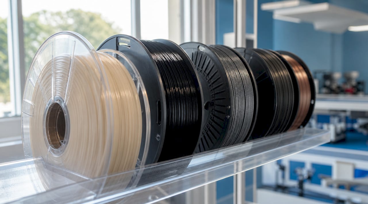
Engineer inspecting filament material spools

Explaining Advanced Filament Materials for Engineers


TL;DR:

  • Advanced filament materials include high-performance thermoplastics and composites designed for demanding applications. Proper hardware, drying, and environmental controls are essential for successful printing with these materials. Selecting the right filament depends on your application’s thermal, mechanical, and regulatory requirements, not solely on data sheets.

Advanced filament materials are specialized thermoplastics and composites engineered to deliver mechanical, thermal, and functional performance that standard PLA or ABS cannot match. Explaining advanced filament materials means understanding not just what they are made of, but how their composition dictates every aspect of the printing process, from nozzle selection to chamber temperature. The field now spans 23 or more distinct filament types, organized across four categories: General, Aesthetic, Functional, and Engineering. Suppliers like 3DXTECH, Prusament, and Sigma Filament have pushed materials like PEEK, PEKK, carbon fiber composites, and ESD-safe polymers into production-grade workflows. If you are selecting materials for functional prototypes, aerospace components, or electronics housings, this guide covers what you need to know.

What are the main types of advanced filament materials?

The four filament categories map directly to application complexity, and understanding where your project falls determines everything downstream. General-purpose filaments like PLA and PETG cover the majority of prototyping work. Aesthetic filaments such as silk PLA or wood-fill prioritize surface finish over structural performance. Functional filaments, including TPU and ASA, add flexibility or UV resistance. Engineering-grade materials, the focus here, are built for load-bearing, high-temperature, or chemically aggressive environments.

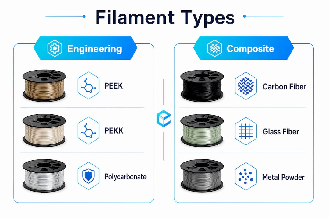
Engineering-grade vs. composite filaments

Engineering polymers like PEEK, PEKK, Ultem (PEI), and polycarbonate (PC) are pure thermoplastics processed at extreme temperatures. Composite filaments blend a base polymer with reinforcing agents: carbon fiber, glass fiber, or metal powder. The distinction matters because composites add stiffness and reduce weight, while pure engineering polymers prioritize thermal stability and chemical resistance. PLA-CF, PA6-CF, and PET-CF look similar on a spool but behave very differently under heat and moisture exposure.

Close-up of PEEK and composite filament spools

Metal filaments: composite vs. sinterable

Metal filaments split into two fundamentally different product types. Composite metal filaments blend 5 to 60% metal powder into a polymer matrix, producing heavy, polishable parts that retain plastic mechanics. Sinterable metal filaments contain 80 to 95% metal and require a debinding and sintering process to yield near full-density metal parts. Composite metal filaments cost $25 to $45 per kilogram. Sinterable options run $120 to $565 per kilogram, reflecting the post-processing infrastructure required.

Filament type Base material Key property Typical application
PEEK / PEKK Ultra-polymer 260°C continuous use Aerospace, medical implants
PA6-CF / PA12-CF Nylon + carbon fiber High stiffness, low weight Structural brackets, jigs
ESD-safe PC Polycarbonate + CNT Electrostatic discharge control Electronics housings, aerospace
Sinterable metal 80-95% metal powder Near full-density metal parts Low-volume metal production
TPU / ASA Flexible / UV-stable Elasticity or weatherability Seals, outdoor enclosures

Infographic comparing engineering-grade vs composite filaments

How do material properties affect printing requirements?

The properties of filament materials are not just performance specs. They are printing constraints. A material that requires 380°C extrusion and a 120°C heated chamber will fail on a standard desktop printer regardless of how well the slicer profile is configured. Engineers who treat filament selection as separate from hardware selection consistently run into preventable problems.

Temperature and hardware requirements

Ultra-polymers like PEEK and PEKK require extrusion temperatures between 360°C and 400°C, with PEKK-A offering a slightly wider processing window that makes it more forgiving than PEEK. Both demand enclosed build chambers to maintain ambient temperatures above 100°C and prevent warping from thermal gradients. All-metal hotends are non-negotiable at these temperatures, since PTFE-lined hotends degrade and off-gas above 240°C.

Abrasive composites create a separate hardware problem. Brass nozzles fail quickly on carbon fiber or glass fiber filaments. Hardened steel nozzles last approximately 10 times longer than brass under the same conditions. Ruby-tipped nozzles show no measurable wear after processing 8 kilograms of abrasive material, making them the correct choice for high-volume composite printing. The abrasion ranking from most to least aggressive runs: carbon fiber, glass fiber, metal-fill, glow-in-the-dark, wood-fill, then standard PLA.

Moisture sensitivity and drying protocols

Hygroscopic filaments absorb ambient moisture within hours of exposure, and the consequences show up as bubbling, poor layer adhesion, and degraded mechanical properties. PEKK requires drying at 140°C for four hours before printing. Nylon variants need similar treatment. Maintaining filament dryness with heated dry boxes during the print run is mandatory for consistent results, not optional. Even brief humidity exposure during a multi-hour print can degrade a part that would otherwise meet spec.

Pro Tip: For carbon fiber filaments specifically, minimum layer heights of 0.2mm prevent nozzle jams caused by fiber bridging. Use a direct-drive extruder rather than a Bowden setup to reduce filament snapping from stiffness.

Post-print handling matters as well. Engineering polymers under rapid cooling develop internal stresses that cause warping or cracking after the print completes. Controlled cool-down inside a heated chamber, or annealing in an oven, relieves these stresses and stabilizes dimensional accuracy. The Cc3dlabs guide on post-processing techniques covers these protocols in detail.

What should engineers consider when selecting advanced filaments?

Selecting the right material starts with defining the operating environment of the finished part, not with browsing a filament catalog. The properties that matter most vary by application, and the trade-offs between printability and performance are real.

Here is a structured decision framework for material selection:

  1. Define the thermal ceiling. What is the maximum continuous-use temperature the part will experience? PETG handles up to roughly 80°C. ASA extends that to around 95°C. PC and Nylon push past 110°C. PEEK and PEKK sustain performance at 260°C. Match the material to the actual thermal load, not the worst-case scenario.

  2. Assess mechanical requirements. Carbon fiber reinforced filaments like CarbonX PA6-CF or PET-CF deliver high stiffness-to-weight ratios suited for structural brackets and tooling. Pure engineering polymers like PEEK offer better impact resistance and chemical compatibility for fluid-contact parts.

  3. Factor in electrical requirements. ESD-safe filaments developed with carbon nanotube technology meet conductivity and flame-retardant standards for electronics and aerospace applications. Prusament PC Space Grade achieves less than 0.25% total mass loss per ESA outgassing standards, making it viable for space-adjacent applications on standard desktop hardware.

  4. Calculate total cost of ownership. Engineering-grade polymers cost $120 to $565 per kilogram. That figure does not include the hardware investment in hardened nozzles, enclosed chambers, or dry storage. Composite filaments at $25 to $45 per kilogram offer a lower entry point but require the same abrasion-resistant hardware. For a detailed breakdown of cost factors, the Cc3dlabs resource on reducing printing costs is worth reviewing.

  5. Evaluate post-processing needs. Sinterable metal filaments require debinding at 200 to 300°C and sintering at 800 to 1,100°C. Sintered parts achieve 96 to 99% theoretical density with mechanical properties close to wrought metal, but the process requires specialized furnace equipment or an outsourced sintering service.

Pro Tip: Most print jobs do not require engineering-grade materials. Confirm that the performance gap between a functional filament like ASA or PC and a full ultra-polymer actually matters for your application before committing to the added setup complexity.

What advanced filaments are shaping manufacturing innovation?

The materials driving the most significant changes in additive manufacturing workflows share one characteristic: they close the gap between printed parts and traditionally manufactured components. The engineering filament category is where this convergence is most visible.

PEEK and PEKK have become the benchmark for extreme-environment applications. 3DXTECH’s CarbonX PEKK-A CF15 combines the thermal stability of PEKK with 15% chopped carbon fiber reinforcement, producing parts that compete with machined composites at a fraction of the lead time. The wider processing window of PEKK-A compared to standard PEEK makes it accessible on a broader range of high-temperature printers without sacrificing structural integrity.

ESD-safe filaments represent a different kind of advancement. Rather than maximizing mechanical strength, these materials meet regulatory thresholds for electrostatic discharge protection and flame retardancy. Advanced filament materials in this category now emphasize regulatory compliance over raw mechanical performance, reflecting a shift toward industrial production standards rather than prototype-only applications.

Material Supplier example Key advancement Target sector
PEKK-A CF15 3DXTECH CarbonX Wide process window + CF reinforcement Aerospace, defense
PC Space Grade Prusament Low outgassing, desktop-printable Space, electronics
PA6-CF Multiple Stiffness-to-weight for structural parts Automotive, tooling
Sinterable 316L SS Sigma Filament Near-wrought density via sintering Low-volume metal production

Sinterable metal filaments from suppliers like Sigma Filament are redefining low-volume metal part production. The ability to print a near-full-density 316L stainless steel part without DMLS equipment removes a significant cost barrier for product developers running pre-production validation. The trade-off is process complexity, but for teams already managing multi-step manufacturing workflows, debinding and sintering are manageable additions.

Key takeaways

Advanced filament materials require matching material properties to both the application environment and the printer hardware before a single layer is deposited.

Point Details
Four filament categories General, Aesthetic, Functional, and Engineering map to application complexity and cost.
Hardware must match the material Abrasive composites need hardened steel or ruby nozzles; ultra-polymers need all-metal hotends above 300°C.
Moisture management is non-negotiable PEKK and Nylon require pre-print drying and heated dry boxes during printing to maintain part quality.
Metal filaments are not interchangeable Composite metal filaments retain plastic mechanics; sinterable filaments yield near-wrought-density metal parts.
Regulatory compliance drives selection ESD-safe and low-outgassing filaments are chosen for compliance thresholds, not just mechanical specs.

What working with advanced filaments actually taught me

The most common mistake I see engineers make is treating filament selection as a spec-matching exercise. They find a material with the right tensile strength and heat deflection temperature, order a spool, and then discover their printer cannot maintain the required chamber temperature or their nozzle is destroyed after two prints. The material was correct. The system was not ready for it.

Thermal management is where most advanced filament projects fail in practice. A PEKK print that warps is almost never a slicer problem. It is a chamber temperature problem, or a drying protocol that was skipped because the timeline was tight. I have seen parts that looked perfect off the bed develop stress cracks 48 hours later because the cool-down was too fast. Controlled environments are not a luxury for these materials. They are the process.

The other thing worth saying plainly: most applications do not need PEEK. The instinct to reach for the highest-performance material available is understandable, but it adds cost, setup time, and failure modes that a well-chosen PC or PA12-CF would have avoided entirely. The right material is the one that meets the spec with the least process complexity, not the one with the most impressive data sheet. For teams building toward production, the Cc3dlabs overview of manufacturing-grade workflows addresses this trade-off directly.

— Justin

How Cc3dlabs handles advanced filament applications

https://cc3dlabs.com

CC 3D Labs operates near Philadelphia with the hardware and process controls that engineering-filament work requires — enclosed build chambers, hardened nozzles, and established drying protocols for hygroscopic polymers. Our farm runs materials like PC, carbon-fiber nylon (PA-CF), PETG, and ASA; ultra-high-temperature polymers such as PEEK and PEI (ULTEM) require industrial systems beyond a standard service fleet, and we’ll tell you when a part genuinely calls for them. If your project involves PEEK, carbon fiber composites, ESD-safe materials, or sinterable metal filaments, outsourcing to a team that has already solved the setup problems saves significant time and reduces material waste. Cc3dlabs handles both prototype quantities and batch production runs, with design support and free online estimates available. Explore the full range of professional 3D printing services to find the right fit for your next engineering project.

FAQ

What are advanced filament materials in 3D printing?

Advanced filament materials are engineering-grade thermoplastics and composites, including PEEK, PEKK, carbon fiber reinforced nylons, ESD-safe polymers, and sinterable metal filaments, designed for applications requiring high thermal, mechanical, or functional performance beyond standard PLA or ABS.

How do I choose the right filament for an engineering part?

Start by defining the maximum operating temperature, mechanical load, and any regulatory requirements such as ESD safety or outgassing limits, then match those constraints to a filament category before evaluating cost and printer hardware compatibility.

Why do advanced filaments require special nozzles?

Abrasive filaments like carbon fiber and glass fiber wear through brass nozzles rapidly. Hardened steel nozzles last roughly 10 times longer, and ruby-tipped nozzles show no measurable wear after 8 kilograms of abrasive material, making them the correct hardware choice for composite printing.

What is the difference between composite and sinterable metal filaments?

Composite metal filaments blend 5 to 60% metal powder into a polymer base and produce heavy, polishable parts that retain plastic mechanics. Sinterable metal filaments contain 80 to 95% metal and require debinding and sintering to achieve 96 to 99% theoretical density with near-wrought mechanical properties.

Do advanced filaments need to be dried before printing?

Yes. Hygroscopic filaments like PEKK and Nylon absorb moisture quickly and must be dried before printing. PEKK requires drying at 140°C for four hours, and a heated dry box during the print run is necessary to maintain consistent mechanical properties and prevent defects.