
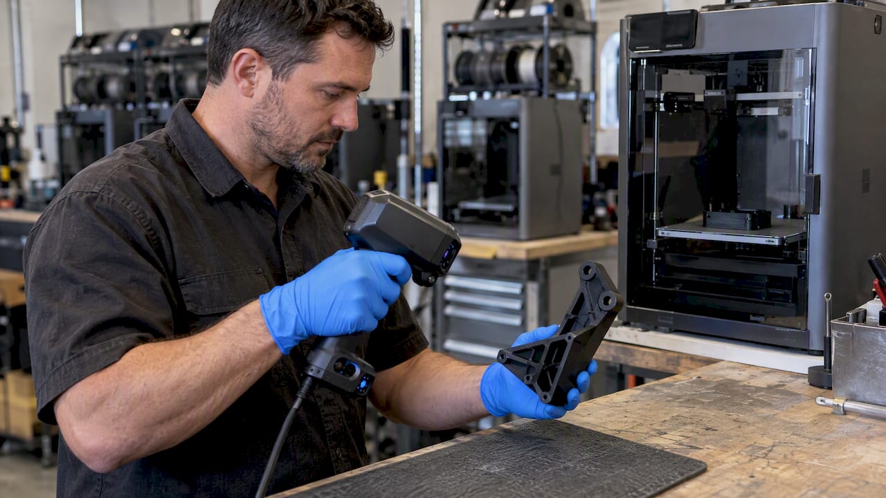
Scan-based quality control means capturing the full surface of a finished part as a 3D point cloud or mesh, aligning it to the nominal CAD model, and reading the differences as numbers and color. Instead of a handful of caliper readings at chosen points, you get thousands of comparisons across the entire geometry. That makes it well suited to freeform surfaces, warped or shrunk prints, cast and molded parts, and reproduced legacy components. It is only as trustworthy as the measurement process behind it, which is where most of this article focuses.
TL;DR
- Scan-based inspection compares a scanned part to its CAD nominal and reports deviation across the whole surface, not just at probed points.
- It is a detective control: it finds nonconformance after a part exists. Its value grows when you trend the data and feed it back into the process.
- A scanner with good specifications is not a validated inspection system. Fixturing, alignment, lighting, and operator technique all add variation, so run a measurement system study before trusting pass/fail results.
- Match the method to the tolerance. Professional handheld scanning with accuracy to ~0.1 mm suits many prototype, reverse-engineering, and FDM-part checks, but not every tight-tolerance feature.
- At CC 3D Labs we scan, clean up the data, and model to CAD in Bucks County, PA, and quote each job individually.
Table of Contents
- What scan-based quality control actually is
- Detective control, not the whole quality system
- Where scanning beats traditional measurement, and where it does not
- Matching scanner accuracy to your tolerance
- Validate the measurement system before you trust it
- Scan cleanup and alignment: where inspection results are won or lost
- Plan the inspection before you scan
- Practical uses for small shops and product teams
- Our perspective: what we would tell a buyer before a scan
- Working with CC 3D Labs
- Frequently asked questions
- Get a quote
- Sources
What scan-based quality control actually is
The core workflow is the same whatever scanner you use:
- Prepare the part. Clean it, deal with shiny or dark surfaces, and add reference targets where the geometry is too featureless to track.
- Scan. Capture all surfaces that matter, with overlap, in a stable environment.
- Process. Merge passes, remove noise and stray points, and produce a watertight mesh or a cleaned point cloud.
- Align. Register the scan to the nominal CAD, either by best fit or, better for inspection, by the datum scheme on the drawing.
- Compare and report. Generate a color deviation map, section cuts, and values at the features that carry tolerances.
The result is a visual that a machinist, a buyer, or an engineer can read in seconds: where the part is high, where it is low, where it twists. A caliper tells you a hole is 0.15 mm oversize. A scan also shows that the whole flange has bowed 0.3 mm, which is usually the more useful finding.
Detective control, not the whole quality system
The American Society for Quality draws a clear line: quality control is product-focused and detective, verifying that parts conform to specification after they exist. Scanning is a very good detective tool. It does not prevent a bad part by itself.
The preventive step happens when you keep the scan results from each batch and look at them over time. If the same boss drifts 0.1 mm further each run, or one corner of every print lifts, that pattern points to a process cause: a worn tool, a changed material lot, a slicer setting, a mold that is moving. A shop that only files pass/fail stamps never sees it. A sheet metal fabricator describing how it controls precision parts through the production chain shows the same principle from another process: inspection results are most useful when they change what happens upstream.
Where scanning beats traditional measurement, and where it does not
| Method | Strength | Limitation |
|---|---|---|
| Calipers, micrometers, gauges | Fast, cheap, familiar for simple prismatic features | Few points, operator-dependent, poor on curves and freeform surfaces |
| Coordinate measuring machine (CMM) | Very high accuracy on defined features, established reporting | Slow for complex surfaces, needs programming and fixturing, often a bottleneck |
| Handheld 3D scanning | Whole-surface capture, color deviation maps, works on awkward or large parts, fast to set up | Accuracy limited by scanner class, surface finish, and technique; weaker on small tight-tolerance features |
| Visual or vision-based checks | Good for cosmetic defects and presence/absence | Not a dimensional measurement on its own |
The honest summary: for tight GD&T on machined features, a CMM remains the reference. For organic shapes, reproduced parts, large assemblies, warped prints, and quick first-article looks, scanning gives information the other methods cannot. Industry practice reflects this: Quality Magazine describes how first article inspection with 3D scanning can work as a “virtual CMM”, with software measuring the scanned part and generating a report much as a probed inspection would.
Matching scanner accuracy to your tolerance
Before you scan anything for inspection, compare the scanner’s accuracy with the tolerance you are verifying. A common rule of thumb in measurement practice is that the instrument should be several times better than the tolerance band. That ratio is a general guideline, not a regulation, so check what your customer or drawing requires.
Our professional handheld 3D scanning has accuracy to ~0.1 mm. Here is how that lines up with typical work:
- FDM printed parts. FDM printing typically holds roughly ±0.2 to 0.5 mm depending on geometry, material, and printer tuning. A scanner at ~0.1 mm can resolve warpage, shrinkage, and fit problems at that scale.
- Reverse engineering. For capturing a legacy or automotive part so it can be modeled and reproduced, ~0.1 mm is comfortably useful for most mating surfaces.
- Fit checks of cast, molded, or fabricated parts. Good for flatness, profile, and overall shape deviations.
- Tight-tolerance machined features. If your drawing calls for a few hundredths of a millimeter on a bore, use a CMM or a dedicated gauge. We would rather tell you that up front than scan a part we cannot honestly verify.
Validate the measurement system before you trust it
This is the step most buyers skip, and it is the one that matters most for any critical-to-quality dimension.
ASQ’s guidance on measurement system analysis frames it plainly: measurement system analysis studies the variation contributed by the act of measuring itself. Every reading is the real part-to-part variation plus the measurement variation. If the second piece is large, your accept-or-reject calls are unreliable.
Two points from ASQ’s Quality 4.0 guidance are worth building into your process:
- Automation does not remove variation, it moves it. Automated scanning removes the human appraiser but introduces lighting, fixturing, model-fitting algorithms, and data processing noise. Treat the scanning setup as a measurement system and validate it before you rely on its pass/fail output.
- Calibration is not Gage R&R. Calibration documents an instrument’s bias in isolation. A Gage R&R characterizes the whole process, including operators, fixtures, and environment. A well-calibrated scanner can still fail a Gage R&R if the way the part is seated introduces consistent error.
If you are ordering inspection scans to support a go/no-go decision, ask for a repeatability check on your own part: scan it several times, re-seat it between scans, and compare the results on the dimensions you care about. Then decide whether the spread is small enough for your tolerance.
Also keep in mind that scanner performance claims are not always comparable. NIST notes that many manufacturers specify sensor performance in non-standard ways, which is one reason it supports standards work for 3D imaging systems. Related test methods exist, such as ASTM E2919-22, a test method for evaluating 3D scanners for static pose. Ask any vendor, including us, exactly how an accuracy figure was established and what it applies to.
Scan cleanup and alignment: where inspection results are won or lost
Many people searching this topic want to know about scan cleanup for CAD, and for good reason. Raw scan data is not an inspection result. What you do next changes the numbers.
Cleanup
Cleanup removes stray points from background objects, fills small holes from occluded or reflective areas, and reduces noise. Aggressive smoothing can hide real defects such as a shallow sink or a small burr, and aggressive hole filling can invent geometry that was never there. For inspection, we keep cleanup conservative and note anything that was filled or smoothed.
Alignment
Best-fit alignment spreads error across the whole part, which can make a distorted part look better than it is. If the drawing defines datums, align to them so the report reflects how the part will actually locate in the assembly. Different alignment choices on the same scan can produce visibly different deviation maps, so record which one was used.
From mesh to CAD
When the goal is to reproduce a part rather than inspect it, the mesh becomes the reference for reverse-engineering CAD. A designer rebuilds clean surfaces and features, applying design intent: making holes round, planes flat, and fillets consistent instead of copying every scanned imperfection. Our 3D scanning checklist and our piece on how to optimize 3D scan accuracy cover the preparation that makes this step cleaner.
Plan the inspection before you scan
ASME publishes a standard on dimensional measurement planning, aimed at ensuring that dimensional measurements are correct and acceptable. You do not need a formal standard for every job, but the habit is good: write the plan first. A workable plan for a scan inspection includes:
- Which features are critical, and their tolerances
- The datum scheme and how the part will be located
- The acceptable measurement uncertainty relative to tolerance
- Surface prep and any reference targets
- The deliverable format: color map, section views, feature table, or all three
- How many parts will be scanned, and how results will be compared across them
That plan keeps the scan focused. Scanning everything and deciding later what to measure is how teams end up with large files and no answer.
Practical uses for small shops and product teams
Checking printed prototypes against CAD
A scanned print shows where it warped, shrank, or deviated from the model. That feedback lets you adjust the CAD or the print settings before you commit to a batch. Our guide on part validation in 3D printing explains how this ties into manufacturing decisions.
Verifying a reproduced automotive or restoration part
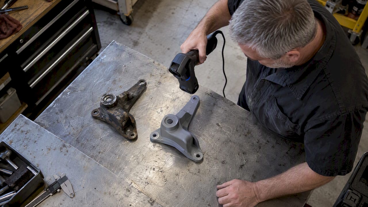
For automotive shops and restorers, scanning the original and then scanning the reproduction closes the loop. You see whether the new part matches the old one at the mounting points and mating surfaces. A compatibility mindset helps here too: a parts supplier’s compatibility checklist for heavy truck components is a reminder that confirming fit before installation saves rework, and a deviation map is a direct way to confirm it.
Batch consistency in small-run production
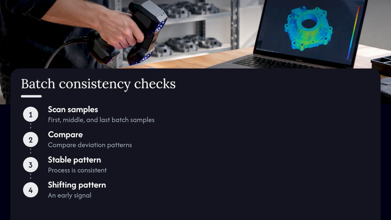
For low-volume runs, scan a sample from the first, middle, and last of the batch, then compare. If the deviation pattern is stable, the process is consistent. If it moves, you have an early signal. Our notes on low-volume manufacturing with 3D printing go deeper on batch planning.
Keeping the data trustworthy
Inspection data is a record. File naming, version control, and the link between a scan and a specific part revision all matter. We wrote about this in why 3D scan data integrity is crucial for manufacturing.
Our perspective: what we would tell a buyer before a scan
We run a production farm of Bambu Lab FDM printers and scan with professional handheld equipment, so we see both sides of inspection: making parts and measuring them. Our view is plain. Scanning is most valuable when the question is about shape, fit, and drift across a whole part, and least valuable when someone wants a single certified number on a tight bore.
That is why we describe our scanning as professional handheld 3D scanning with accuracy to ~0.1 mm and stop there. We do not claim certifications, and we do not present a scan as a substitute for a calibrated CMM report. What we can do is give you a clean, well-aligned deviation map, a cleaned mesh, or a CAD model built from the scan, along with a clear note of what was done to the data.
We also quote each job individually. Every production job starts with a test print of your actual model, and we do not publish fixed pricing or blanket turnaround promises, because part size, material, and finish requirements change the work. If a part is beyond what our equipment can honestly verify, we will say so before you spend money.
— Justin
Working with CC 3D Labs
If you need a part verified, reproduced, or modeled, our 3D Scanning Lab handles handheld scanning for reverse engineering, legacy and automotive part reproduction, and scan-to-CAD modeling. Our CAD modeling services turn the scan into an editable model, and our Custom 3D Printing covers prototypes, functional parts, and small batches in materials such as PLA, PETG, ABS, ASA, PC, and carbon-fiber nylon. We are based in Bucks County, PA, offer residential pickup for local customers (there is no walk-in storefront), and ship completed orders anywhere in the United States.
Frequently asked questions
Is 3D scanning accurate enough for dimensional inspection?
It depends on your tolerance. Professional handheld scanning with accuracy to ~0.1 mm suits many prototype, reproduction, and FDM part checks, where typical print tolerances are around ±0.2 to 0.5 mm. For tight-tolerance machined features, a CMM or dedicated gauge is the better choice.
Can a scan replace a CMM report?
Not in every case. A scan gives whole-surface deviation that a CMM cannot produce quickly, while a CMM gives higher accuracy on defined features. Many teams use both, with scanning for shape and fit and a CMM for the few critical dimensions.
What is scan cleanup, and does it change the inspection result?
Cleanup removes noise and stray points and closes small holes in the raw data. Done carefully it has little effect on measured deviation. Heavy smoothing or hole filling can hide or invent features, so the steps should be documented with the report.
How do I know the scan results are reliable?
Run a repeatability check on your own part: scan it several times, re-seat it each time, and compare the dimensions you care about. For critical features, a formal Gage R&R from the measurement system analysis approach described by ASQ is the standard way to judge the whole process.
Get a quote
To have a part scanned, request a quote at cc3dlabs.com/3d-scan-quote/. For printing, use cc3dlabs.com/3d-print-quote/, and for reverse-engineering CAD, cc3dlabs.com/3d-modeling-cad-quote/.
Sources
- ASQ: How to Hire a Quality Control Inspector
- ASQ: Measurement System Analysis and Gage R&R
- ASQ: Quality 4.0 and AI in Quality
- Quality Magazine: First Article Inspection with 3D Scanning
- NIST: Standards and performance metrics for 3D imaging systems
- NIST: ASTM E2919-22 orientation and uncertainty method
- ASME: Dimensional Measurement Planning