
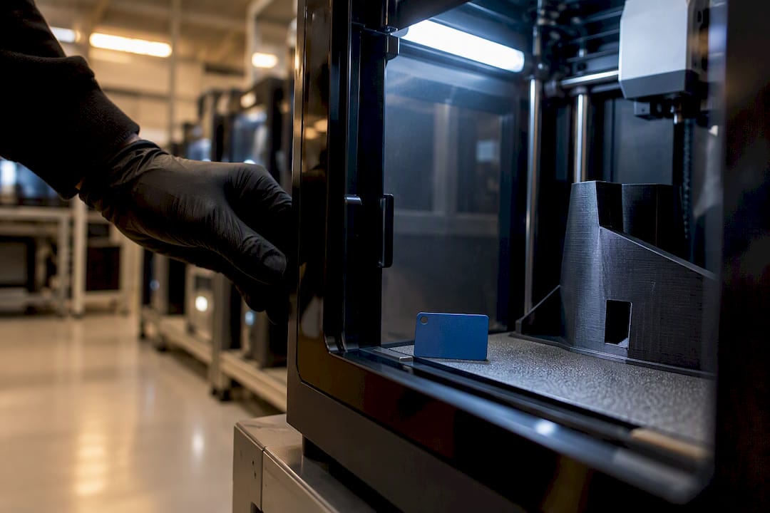
In this article, “ITAR 3D printing” refers to professional FDM printing and handheld 3D scanning for prototypes, functional parts, and low-volume production runs, not export-control compliance work. Product developers, engineers, and automotive or restoration shops use this combination to turn a worn part, a rough sketch, or a CAD file into something they can hold and test. The typical deliverables are printed parts in materials like PETG or ABS, scan-derived CAD models ready for editing, and a test print that becomes the basis for a full production quote.
TL;DR:
- FDM material selection determines a part’s real-world load capacity, with PETG suitable up to 80°C and ABS or ASA handling up to 100°C before warping risks arise.
- Handheld 3D scanning achieves about 0.1 mm accuracy, but reflective or black surfaces require treatment, and higher resolution reduces cleanup work for tight tolerances.
- Proper design review includes wall thickness, orientation along load paths, and realistic tolerances, with split parts and minimal supports improving print success.
- Most quotes are based on a test print that reveals actual material performance and fit, rather than relying on fixed pricing, delaying formal quotes until after validation.
- ITAR compliance requires strict control over digital files and physical parts, including secure storage, limited access to verified U.S. persons, and proper classification before export licensing.
Table of Contents
- What FDM Materials Actually Handle Real-World Loads?
- How Accurate Is Handheld 3D Scanning for Reverse Engineering?
- Design-for-Manufacturability Checklist Before You Send Files
- What Tolerance and Accuracy Can You Actually Expect?
- How the Quoting and Production Process Actually Works
- Why CC 3D Labs Fits This Kind of Work
- What ITAR Compliance Actually Requires for 3D Printed Parts
- Handling and Storing ITAR-Controlled Files and Parts
- Getting ITAR Licenses and Export Classifications in Order
- Security Practices for ITAR-Compliant 3D Printing Workflows
- Common Defense Applications of 3D Printing Under ITAR
- Outsourcing FDM Printing vs. Buying Your Own Equipment
- How to Request a Quote and What to Send
- Sources
- FAQ
What FDM Materials Actually Handle Real-World Loads?
Material choice decides whether a part survives its job or cracks on the first stress test. PLA prints easily and holds tight tolerances, but it softens around 60°C, which rules it out for anything sitting near an engine bay or in direct sun. PETG trades a little dimensional crispness for real toughness and chemical resistance, and it tolerates roughly 80°C before it starts to deform. ABS and ASA push heat and UV resistance further, into the 100°C range, but both are prone to warping and layer splitting if the print isn’t managed carefully. Polycarbonate (PC) and carbon-fiber-filled nylon sit at the top of the FDM strength ladder, offering serious mechanical performance for functional parts, but they demand a hardened nozzle and a hot end capable of sustained high temperatures.
A few practical notes matter more than most people expect:
- Nylon and PC absorb moisture from the air, and a damp spool prints brittle, stringy parts no matter how well the printer is tuned.
- Filament should be dried before use and stored in sealed containers with desiccant between jobs.
- Carbon-fiber nylon chews through brass nozzles fast, so it needs hardened steel components to hold tolerance over a production run.
- If a part needs to survive a hot engine compartment or repeated flexing, ask for an engineering-grade filament or a post-print annealing step rather than assuming PLA will scale up.
CC 3D Labs runs its production farm on Bambu Lab P1S printers, chosen partly because their enclosed chambers help stabilize temperature-sensitive materials like ABS and ASA across long runs.
How Accurate Is Handheld 3D Scanning for Reverse Engineering?
Professional handheld 3D scanning delivers accuracy to about 0.1 mm, tight enough to capture the geometry of a discontinued bracket, a cracked intake manifold, or a custom-fit automotive panel without an original CAD file to reference. The typical workflow moves from a raw aligned mesh to a cleaned watertight mesh, then, on request, into a parametric CAD file in STEP or IGES format that an engineer can actually edit.
The most common use cases at CC 3D Labs’s 3D scanning lab are legacy automotive parts that no longer exist in any catalog, damaged components that need to be rebuilt from a mating survivor, and fit-check work where a new part has to slot into an existing assembly.
Scanning has real limits, though. Reflective chrome trim and thin-walled features tend to confuse a scanner’s optics, and glossy black plastic can behave almost like a mirror.
- A light dusting of matte developer spray on reflective surfaces improves scan capture dramatically.
- Small or lightweight parts often scan more cleanly when mounted in a simple fixture instead of held by hand.
- Higher scan resolution reduces the cleanup work needed before a mesh is print-ready, which directly affects how tight the final part’s tolerances can be.
Pro Tip: If a part will be printed multiple times, ask for a full CAD re-creation rather than a raw mesh export. A parametric model lets you adjust wall thickness or tolerances later without rescanning.
Design-for-Manufacturability Checklist Before You Send Files
A few minutes of design review before submitting a file for a quote saves a full print cycle of trial and error. Use this sequence:
- Check wall thickness. As a rough range, keep structural walls at 1.5 to 3 mm depending on material; thinner sections in PLA can survive where the same thickness in ABS would flex or crack under load.
- Plan orientation around load paths. FDM parts are inherently anisotropic. Layers bond well in-plane but resist pulling apart across layers far less. Orient the part so critical stresses run parallel to the layers, not perpendicular to them.
- Set realistic tolerances for mating parts. A practical FDM baseline runs ±0.2 to 0.5 mm depending on geometry and material. If a bore needs to be press-fit, plan for a light reaming pass rather than expecting the printed hole to be final.
- Minimize support structures. Chamfer downward-facing overhangs where possible, and consider splitting a complex part into two simpler bodies that bond together instead of forcing a printer to bridge long unsupported spans.
- Annotate the file. Flag critical dimensions, required fits, and any surface finish expectations directly on the drawing or in the submission notes.
- Pick the right file format. Send STEP files for assemblies where geometry needs to stay editable, and STL for single-body prints where the mesh is final.
Pro Tip: Anisotropy is the single biggest reason a “working” prototype fails in the field. A snap-fit tab or a screw boss almost always needs its layer lines running with the stress, not against it.
What Tolerance and Accuracy Can You Actually Expect?
A practical baseline for production-farm FDM work is a dimensional tolerance range that typically varies with part geometry, wall thickness, and material behavior during cooling. NIST’s research on polycarbonate parts made by fused filament fabrication found that reducing layer height, raising nozzle temperature, and applying extrusion compensation can push geometric deviation down to very low levels in controlled testing, though real-world parts with complex geometry rarely hit that ceiling consistently.
Nozzle temperature, layer height, and extrusion rate all interact to change both the outer geometry and the strength of the bond between layers. NIST’s work on optimizing FFF process parameters under uncertainty shows that physics-informed calibration of these settings reduces variability far more reliably than adjusting them by trial and error.
Before signing off on a batch, most shops rely on a short acceptance sequence:
- Visual inspection for layer separation, warping, or surface defects.
- Caliper checks against critical dimensions on the drawing.
- A physical fit trial in the actual assembly.
- A simple CMM check for parts where a mating tolerance is unusually tight.
This is why the test piece is printed before quoting a production run. It catches geometry or material issues while they’re cheap to fix, not after fifty parts are already off the printer. For readers who want a formal benchmark, NIST’s Additive Manufacturing test artifact offers a standardized way to measure an AM system’s geometric accuracy, and it can serve as a shared acceptance piece between a buyer and a print provider.
How the Quoting and Production Process Actually Works
Getting from a file to finished parts follows a consistent sequence:
- Submit an inquiry with your CAD or scan files, target material, and intended use.
- File review, where orientation, wall thickness, and any tolerance flags get checked against the requested material.
- Material and orientation recommendation based on the part’s mechanical requirements.
- Test print, which validates fit, finish, and critical dimensions before committing to volume.
- Custom quote, built from what the test print actually revealed rather than a generic price list.
- Approval and production run, followed by shipping or pickup.
To speed that process, include the number of parts needed, the end use (decorative, functional, load-bearing), any critical dimensions with tolerances, and whether a specific surface finish matters. There’s no fixed price sheet here. Every job is quoted individually after a test print confirms material behavior and fit, so budgeting internally means treating the test print as the moment real numbers appear, not the initial inquiry.
Local customers in the Greater Philadelphia area use residential pickup rather than a walk-in storefront, and finished orders ship anywhere in the United States. Fragile or thin-walled parts should be flagged at inquiry so they can be packed with appropriate bracing rather than tossed in a box with loose padding.
Why CC 3D Labs Fits This Kind of Work
CC 3D Labs runs a production farm of Bambu Lab FDM printers out of Bucks County, Pennsylvania, covering PLA, PETG, ABS, ASA, PC, and carbon-fiber nylon, with multicolor and multi-material printing available on qualifying jobs. The 3D scanning lab handles reverse engineering and legacy part reproduction using professional handheld 3D scanning with accuracy to about 0.1 mm, paired with CAD modeling services for readers who need a scanned mesh turned into an editable model.
This setup fits automotive restoration jobs where an original part no longer exists, product developers iterating toward a production-ready prototype, and small businesses that need a short manufacturing run without committing to injection tooling. Every job still runs through the same test-print-first process before a quote is finalized, whether you’re starting with 3D printing, scanning, or CAD work.
What ITAR Compliance Actually Requires for 3D Printed Parts
The International Traffic in Arms Regulations govern the export of defense articles and related technical data, and that scope extends to digital files used to manufacture controlled parts, not just physical hardware. A CAD model, a slicer file, or a scan of a defense-related component can itself count as controlled technical data under the regulations administered by the U.S. Department of State’s Directorate of Defense Trade Controls.
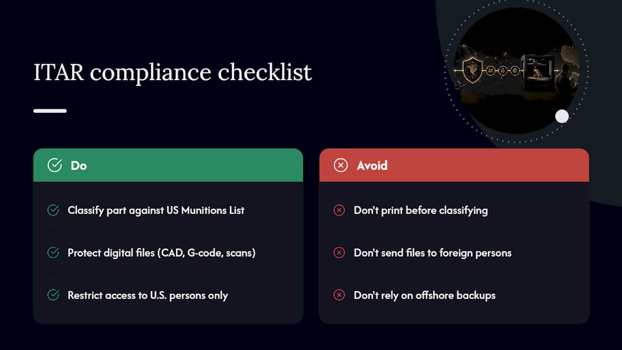
For a shop or engineering team handling this kind of work, compliance starts with correctly classifying the part against the United States Munitions List before any file gets printed, scanned, or transmitted. That classification determines whether the item falls under ITAR at all, or under a separate export control regime like the Export Administration Regulations. Getting that classification wrong at the outset creates risk that no amount of careful printing practice can fix later.
Because ITAR treats technical data broadly, a company printing a defense-related part needs controls not just on the physical part leaving the building, but on every digital file that describes it. That includes CAD source files, sliced G-code, scan meshes used for reverse engineering, and even design revisions exchanged by email. Any of those can constitute a controlled export if they reach a foreign person or leave U.S. soil, even unintentionally through a cloud backup or an offshore contractor.
Handling and Storing ITAR-Controlled Files and Parts
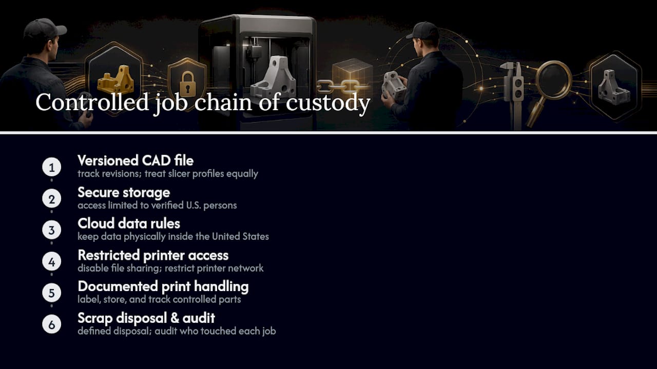
Digital file discipline is where most ITAR exposure actually happens, since a single misdirected email or an unsecured cloud folder can constitute an unauthorized export. Controlled files need to live on systems with access limited to verified U.S. persons, with any cloud storage configured to keep data physically within the United States and away from foreign-accessible servers.
Physical printed parts carry their own handling requirements. A part manufactured from ITAR-controlled technical data should be stored, labeled, and tracked separately from commercial work, with a documented chain of custody covering who accessed the file, who ran the print, and where the finished part went. Scrap prints, failed test pieces, and even support material removed from a controlled part need a defined disposal process rather than ending up in a general recycling bin.
Version control matters as much as physical security. A revised CAD file or an updated slicer profile for a controlled part should be tracked with the same rigor as the finished part itself, since an outdated file left on a shared drive is still exportable technical data. Companies working in this space typically restrict printer network access, disable unnecessary file-sharing features on production machines, and audit which employees have touched a given job at each stage.
Getting ITAR Licenses and Export Classifications in Order
Before any ITAR-covered part or file moves, the organization handling it generally needs to register with the Directorate of Defense Trade Controls, a required step for manufacturers, exporters, and brokers of defense articles and services, independent of whether an export license has even been requested yet. Registration alone does not authorize an export. It’s the administrative prerequisite that makes a license application possible.
The classification step comes next, and it’s where many companies stumble. A part or its technical data needs to be checked against the United States Munitions List to determine whether it’s ITAR-controlled at all, or whether it instead falls under the Commerce Department’s Export Administration Regulations. Companies uncertain about classification can request a Commodity Jurisdiction determination from the State Department to get an official answer rather than guessing.
If a part or its data is confirmed ITAR-controlled and needs to move to a foreign person or entity, a specific export license or a Technical Assistance Agreement typically has to be approved before that transfer happens. This process can take weeks, and starting it only after a customer deadline is looming rarely ends well.
Security Practices for ITAR-Compliant 3D Printing Workflows
Physical and digital security controls need to work together, since a compliant workflow that’s technically secure but physically open to unauthorized visitors is still a gap. Printer access should be restricted to verified personnel, with production areas handling controlled jobs separated from general shop floor traffic where non-cleared staff or visitors might have line of sight to a screen or a build plate.
Personnel screening matters as much as any firewall setting. Only confirmed U.S. persons should have access to ITAR-controlled files or parts, and that status needs to be verified and documented, not assumed based on someone’s job title or tenure. Foreign nationals, including some visa holders, generally cannot access this material without a specific license exception.
On the digital side, network segmentation keeps production printers handling controlled jobs off networks that also touch general internet traffic or unmanaged devices. Audit logging that records who opened a file, who queued a print job, and when a part left the building creates the paper trail that matters if a compliance question ever comes up. Regular internal audits, rather than a one-time policy document, are what actually catch a gap before it becomes a violation.
Common Defense Applications of 3D Printing Under ITAR
Additive manufacturing has become a genuine tool inside the defense supply chain, and a handful of application types show up repeatedly across the industry. Replacement parts for legacy military equipment are a major use case, since original tooling for decades-old platforms is often long gone, and reverse engineering a worn component into a printable file solves a supply problem that traditional manufacturing can’t touch cost-effectively.
Prototyping for new defense systems is another common thread, where engineering teams use rapid printing to iterate on housings, brackets, and fixtures before committing to final production methods. Tooling and jigs used in the assembly of controlled hardware also frequently fall under ITAR scrutiny, even when the tooling itself isn’t a weapon system, because the technical data behind it describes a controlled process.
Field-deployable repair capability is a newer application, where portable printing setups let military units fabricate certain replacement components closer to where equipment actually breaks down, rather than waiting on a traditional parts pipeline. Each of these categories carries the same underlying requirement: the technical data behind the part, not just the finished object, is what triggers ITAR’s control obligations, and every workflow touching that data has to be built around that fact from the start.
Outsourcing FDM Printing vs. Buying Your Own Equipment
Outsourcing wins when a job needs specialized materials, scan-to-CAD accuracy, or repeatable results across a full batch. Buying a printer makes sense mainly for teams doing very rapid, low-stakes iteration where full control matters more than consistency. What often gets missed is the hidden cost: filament storage, hot-end maintenance, and the time spent re-tuning settings for every new material.
— Justin
How to Request a Quote and What to Send
The fastest path to a real number starts on CC 3D Labs’s services page, where you can see the full range of printing, scanning, and CAD work before deciding which quote form fits your project. For a straightforward printed part, the 3D print quote form is the direct route in.
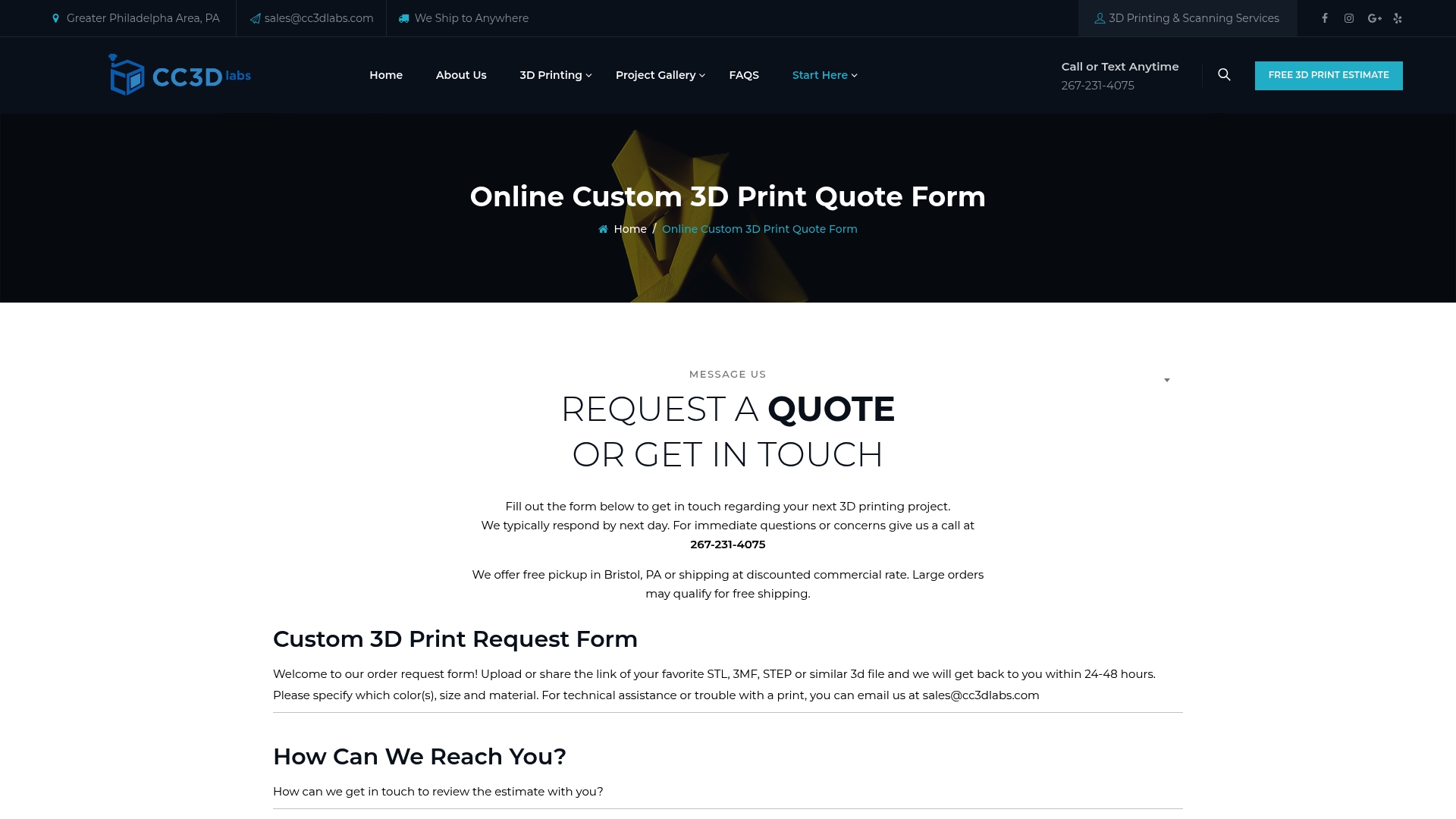
If your project starts with a physical object instead of a file, whether it’s a cracked automotive bracket or a discontinued housing, the 3D scan quote form is the better starting point, and it feeds directly into reverse engineering and CAD reconstruction from there. For work that’s purely CAD, no scanning or printing needed yet, use the CAD quote form instead.
Whichever form you use, include your CAD or scan files, the material you’re considering, the number of parts, the end use, and any critical dimensions with tolerances. That’s what lets a test print get scheduled quickly instead of sitting in a back-and-forth email thread. Remember that every quote follows a test print of your actual part, not a generic catalog price, and that local jobs in the Greater Philadelphia area can be picked up residentially while everything else ships U.S.-wide.
Sources
- Processing-Structure-Property Relationships of Polycarbonate Samples Prepared by Fused Filament Fabrication | NIST
- Bambu Lab P1 Series | Reliable Out-of-the-Box Performance | Bambu Lab US
FAQ
Does CC 3D Labs Handle ITAR-Regulated Defense Parts?
CC 3D Labs focuses on FDM printing, handheld 3D scanning, and reverse engineering for prototypes, automotive restoration, and small-batch production. The company makes no certification claims and does not represent itself as an ITAR-registered defense manufacturer.
What Accuracy Can I Expect From FDM Printing?
A practical baseline for production-farm FDM work runs ±0.2 to 0.5 mm, depending on the part’s geometry and material. Tighter tolerances on mating features usually require a light post-print reaming or fit-adjustment step.
How Accurate Is Handheld 3D Scanning for Reverse Engineering?
Professional handheld 3D scanning at CC 3D Labs delivers accuracy to about 0.1 mm, which is precise enough for reproducing legacy automotive parts and checking fit against existing assemblies. Reflective or very thin-walled surfaces may need a matte spray coating before scanning to capture cleanly.
Why Does CC 3D Labs Quote After a Test Print Instead of Giving a Price Upfront?
Material behavior, orientation, and tolerance needs to vary enough between parts that a fixed price list would be inaccurate for most jobs. A test print confirms fit and finish first, and the quote is built from what that print actually shows.
Can I Get Parts Shipped Outside the Philadelphia Area?
Yes. Local customers in Bucks County and the Greater Philadelphia area typically use residential pickup, since CC 3D Labs has no walk-in storefront, while finished orders ship anywhere in the United States.