TL;DR:
- Surface finish in 3D printing determines the texture, performance, and longevity of printed parts, requiring early specification. Different technologies like FDM, SLA, SLS, and metal fusion produce distinct Ra ranges, influencing post-processing needs. Proper design orientation, material choice, and targeted post-processing ensure optimal functional and aesthetic outcomes.
Surface finish in 3D printing is defined as the measurable texture and topography of a printed part’s outer layer, and it directly determines whether that part succeeds or fails in its intended application. The role of surface finish in 3D printing extends far beyond appearance. It governs fit, friction, fatigue life, sealing performance, and fluid dynamics. Manufacturers working with FDM, SLA, SLS, or metal powder bed fusion processes each encounter distinct surface characteristics tied to their technology. Surface quality is quantified using roughness average (Ra), measured in micrometers, and this single metric carries significant weight in aerospace, medical, and industrial component qualification. This article covers how printing technology, post-processing, and design decisions each shape the final surface outcome.
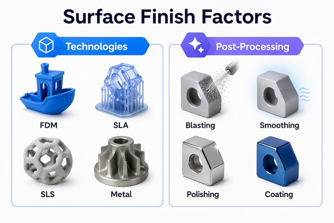
How do different 3D printing technologies influence surface finish?
Every additive manufacturing process produces a characteristic surface texture, and understanding those defaults is the starting point for any finish specification. The root cause of most surface imperfections is the layer-by-layer build process, which creates a staircase effect on curved and angled surfaces. The severity of that staircase depends on layer height, material behavior, and process physics.
FDM (Fused Deposition Modeling) produces the most visible layer lines of any common process. Typical Ra values for FDM parts range from 10 to 30 μm, depending on layer height and material. PLA and ABS parts printed at 0.2 mm layer height show clear bead extrusion ridges that require sanding or chemical smoothing before use in consumer-facing applications.
SLA (Stereolithography) uses a UV laser to cure liquid resin, producing surfaces with Ra values as low as 1 to 3 μm right off the printer. The result is a near-glassy finish that requires minimal post-processing for aesthetic parts. However, support attachment points leave small scars that must be addressed before final use.
SLS (Selective Laser Sintering) fuses nylon powder, leaving a grainy, matte texture with Ra values typically between 6 and 12 μm. The surface has a sandpaper-like quality that works well for functional prototypes but needs bead blasting or dyeing for production parts.
Metal powder bed fusion processes, including DMLS and SLM, produce surfaces with Ra values ranging from 6 to 20 μm. Residual powder particles fused to the surface and layer lines both contribute to roughness. Post-machining or electropolishing is standard for sealing surfaces and bearing interfaces.
| Technology | Typical Ra Range | Primary Surface Issue |
|---|---|---|
| FDM | 10–30 μm | Visible layer lines, bead ridges |
| SLA | 1–3 μm | Support scars, resin blush |
| SLS | 6–12 μm | Grainy powder texture |
| Metal DMLS/SLM | 6–20 μm | Fused powder, staircase effect |
| Material Jetting | 1–4 μm | Waxy surface, UV sensitivity |
Print orientation compounds these effects. Surfaces printed at shallow angles relative to the build plate show the most pronounced staircase stepping. Vertical walls on FDM parts are smoother than 45-degree overhangs because the layer transitions are less visible. Surface finish in additive manufacturing is a critical functional parameter that affects fit, fluid dynamics, wear resistance, and fatigue life across all of these technologies.
What post-processing techniques enhance surface finish?
Post-processing is where manufacturers close the gap between as-printed texture and production-grade quality. The right method depends on material, geometry, required Ra value, and whether the part needs dimensional stability after finishing.
Media blasting and bead blasting are the most common first steps for SLS and metal parts. Blasting removes loose powder, smooths texture, and creates a uniform matte finish. It does not significantly alter dimensions, making it safe for tight-tolerance features. Media blasting and chemical smoothing effectively eliminate stair-stepping effects inherent to layered printing.
Chemical vapor smoothing works by exposing a part to solvent vapor that melts and redistributes the outermost surface layer. For FDM ABS parts, acetone vapor smoothing can reduce Ra from 20 μm down to 2 to 4 μm in minutes. The trade-off is slight dimensional change and the need for controlled ventilation. For nylon SLS parts, dedicated vapor smoothing systems like AMT PostPro3D achieve similar results with better repeatability.
Tumbling and vibratory finishing use abrasive media in a rotating drum to smooth small parts uniformly. This method works well for batches of small, geometrically simple parts but is size-limited and can round sharp edges that are functionally important.
Sanding and polishing remain the most controllable methods for achieving very low Ra values on accessible surfaces. Progressive grits from 120 to 2000, followed by polishing compound, can bring SLA or FDM parts to a mirror finish below 0.5 μm. The limitation is labor cost and the inability to reach internal channels or complex geometry.
Painting and dyeing add color and a protective layer simultaneously. Dyeing is particularly effective for SLS nylon, penetrating the surface rather than coating it, which preserves dimensional accuracy. Painting adds thickness, typically 50 to 100 μm per coat, which must be accounted for on mating surfaces.
| Method | Best For | Ra Improvement | Key Trade-off |
|---|---|---|---|
| Bead blasting | SLS, metal | Moderate | Matte only, no gloss |
| Vapor smoothing | FDM ABS, nylon | High | Slight dimensional change |
| Tumbling | Small batch parts | Moderate | Size and geometry limited |
| Sanding/polishing | Accessible surfaces | Very high | Labor intensive |
| Painting/dyeing | Aesthetics, protection | Low (coating) | Adds thickness |
Pro Tip: Specify your required Ra value before selecting a post-processing method. Working backward from the functional requirement, such as Ra 0.8 μm for a sealing surface, prevents over-processing and unnecessary cost. Learn more about the full spectrum of options in this 3D print finishes guide.
How does surface finish affect functional performance?
Surface roughness is an engineering variable with direct consequences for part performance. Mismanaging surface finish causes technical failures including leaking gaskets, seized parts, and premature fatigue because surface anomalies initiate stress cracks. This is not a cosmetic concern. It is a structural one.
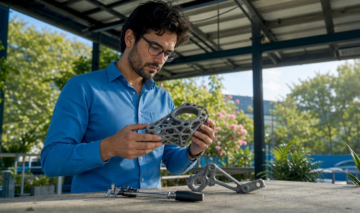
The fatigue life relationship is quantitative. Reducing surface roughness from Ra 3.2 μm to 0.8 μm in metal parts produces fatigue strength improvements of 15 to 30%. For a load-bearing bracket or a cyclic-stress component in a medical device, that improvement can be the difference between a 10-year service life and a premature failure.
Friction and wear behavior depend on surface texture in ways that are not always intuitive. Rough surfaces create higher initial friction and accelerate wear in sliding contact. However, some applications require specific surface textures to retain lubricants, and over-finishing can starve mechanical assemblies of necessary lubrication. A bearing journal polished to Ra 0.1 μm may actually perform worse than one finished to Ra 0.4 μm because the lubricant film cannot be maintained.
Sealing performance adds another layer of complexity. Both too rough and too smooth surfaces can cause leaks or micro-leaks in gasket interfaces. A controlled Ra value, typically between 1.6 and 3.2 μm for most elastomeric gaskets, creates enough texture for the gasket to conform without allowing leak paths through deep valleys.
Fluid dynamics in internal channels are also affected. Rough internal surfaces in printed manifolds or heat exchangers increase turbulent flow and pressure drop. For high-flow hydraulic components, this translates directly to energy loss and heat generation. Electropolishing or abrasive flow machining of internal channels is standard practice in precision fluid systems.
Dimensional accuracy at assembly depends on finish as well. A shaft printed to nominal diameter with Ra 15 μm will measure differently than one finished to Ra 1.6 μm because the roughness peaks add effective material. Understanding this relationship is covered in detail in precision 3D part qualities that every engineer should account for at the design stage.
What design decisions optimize surface finish from the start?
The most cost-effective surface finish strategy begins in CAD, not at the finishing bench. Surface finish is a decisive factor in lifecycle costs and reliability, and decisions made during design and print setup determine how much post-processing will be required.
-
Orient critical surfaces away from support contact. Support structure removal causes surface scarring that compromises dimensional accuracy if not accounted for at the design stage. Placing cosmetic or functional surfaces on self-supporting faces eliminates this problem entirely.
-
Rotate parts to minimize staircase effects on key features. Rotating parts by 45 or 90 degrees optimizes surface finish on sloped features and reduces post-processing time and cost. A cylindrical bore printed vertically will have a smoother inner wall than one printed horizontally.
-
Reduce layer height on finish-critical parts. Dropping from 0.2 mm to 0.1 mm layer height on an FDM part roughly halves the visible staircase amplitude. Print time increases, but post-processing time decreases, and the net cost is often lower for small-batch production.
-
Specify Ra requirements on your drawing before quoting. Suppliers cannot hit a target they have not been given. Defining Ra values for sealing surfaces, bearing interfaces, and cosmetic faces at the RFQ stage prevents mismatched expectations and rework.
-
Account for finishing stock in your CAD model. If a surface will be sanded or machined after printing, add 0.3 to 0.5 mm of material to that face. This preserves final dimensions after material removal.
Pro Tip: For manufacturing-grade 3D printed parts, treat surface finish as a design input, not an afterthought. Document finish requirements in your technical drawing the same way you would a tolerance or material callout.
Support structure scarring is a major contributor to surface defects, and anticipating this during CAD design reduces costly rework and maintains accuracy. The best manufacturers build finish considerations into their design review checklist, not their inspection report.
Key takeaways
Surface finish in 3D printing is a functional engineering parameter that must be specified, designed for, and controlled from the first CAD decision to the final post-processing step.
| Point | Details |
|---|---|
| Technology sets the baseline | FDM, SLA, SLS, and metal processes each produce distinct Ra ranges that define your starting point. |
| Post-processing closes the gap | Methods like vapor smoothing, bead blasting, and polishing can reduce Ra by an order of magnitude. |
| Finish drives functional outcomes | A 15 to 30% fatigue strength gain is achievable by reducing Ra from 3.2 μm to 0.8 μm in metal parts. |
| Over-finishing carries real risk | Surfaces polished below optimal Ra can fail to retain lubricant, causing premature wear in assemblies. |
| Design orientation is the cheapest fix | Rotating a part 45 to 90 degrees during setup reduces staircase effects without adding cost. |
Surface finish is the variable most manufacturers underestimate
I have reviewed hundreds of part drawings from product developers who specify tight dimensional tolerances down to 0.05 mm but leave the surface finish field blank. That blank field is where failures are born. A gasket surface with Ra 12 μm will leak under pressure cycling regardless of how accurate the bore diameter is. A sliding shaft with Ra 25 μm will wear its mating bore in weeks, not years.
The misconception I encounter most often is that surface finish is a cosmetic concern addressed at the end of the process. The reality is the opposite. Finish requirements should appear on the drawing before the first print parameter is set. The technology choice, orientation, layer height, and post-processing sequence all flow from that specification.
What I find genuinely encouraging is how much the as-printed baseline has improved. 3DEO’s Intelligent Layering technology produces production-grade metal parts with smooth surfaces and tight tolerances directly off the printer, which challenges the assumption that additive manufacturing always requires heavy post-processing. That capability is spreading across the industry. The gap between additive and machined surface quality is narrowing every year.
My practical advice: treat surface finish as a first-class design parameter. Write it on the drawing. Discuss it with your print supplier at the quoting stage. And if you are unsure what Ra value your application requires, look at the equivalent machined part specification and use that as your target. The post-processing methods available today can hit almost any target. The question is whether you have defined the target clearly enough to hit it.
— Justin
How Cc3dlabs helps manufacturers achieve production-grade surface finish

Cc3dlabs, based near Philadelphia, works with manufacturers and product developers who need more than a rough prototype. Their FDM printing capabilities cover a range of engineering-grade materials, and their post-processing options include sanding, painting, and finishing tailored to functional requirements. Every project starts with a design review that includes surface finish specification, so parts arrive ready for assembly, not for rework. For teams managing batch production or iterating on functional components, Cc3dlabs offers fast turnaround, free online estimates, and direct design support. Explore their full range of capabilities on the 3D printing services page and request a quote for your next production run.
FAQ
What is surface finish in 3D printing?
Surface finish in 3D printing refers to the texture and roughness of a part’s outer surface, measured as roughness average (Ra) in micrometers. It affects how a part looks, how it fits with mating components, and how it performs under mechanical stress or fluid pressure.
Which 3D printing process produces the smoothest surface?
SLA and material jetting produce the smoothest as-printed surfaces, with Ra values as low as 1 to 3 μm. FDM produces the roughest baseline finish, typically between 10 and 30 μm, and almost always requires post-processing for functional or cosmetic applications.
How does surface roughness affect fatigue life?
Reducing Ra from 3.2 μm to 0.8 μm in metal parts improves fatigue strength by 15 to 30%. Surface irregularities act as stress concentration points where fatigue cracks initiate, so smoother surfaces directly extend component service life.
Can over-polishing a 3D printed part cause problems?
Yes. Some mechanical assemblies require a specific surface texture to retain lubricant. Polishing a surface below the optimal Ra value can prevent lubricant film formation, leading to metal-to-metal contact and accelerated wear.
When should surface finish be specified in the design process?
Surface finish requirements should be specified on the technical drawing before the first print parameter is selected. Early specification allows the print supplier to choose the correct technology, orientation, and post-processing sequence to hit the target at the lowest cost.