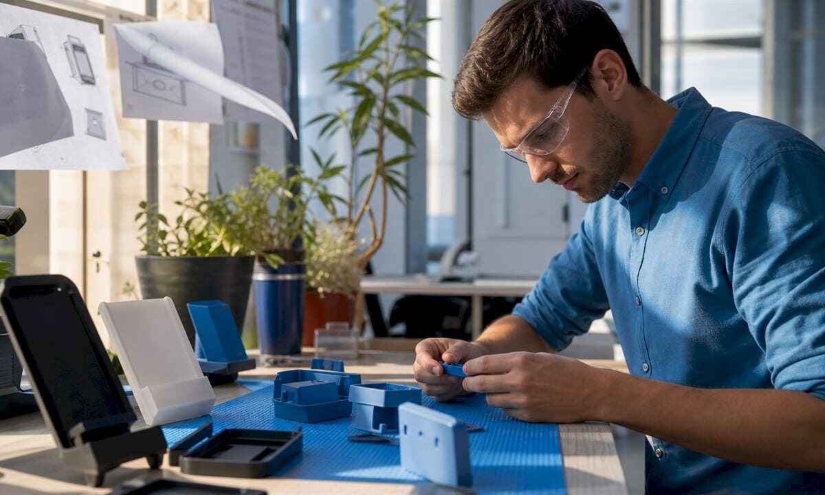
Product developer assembling functional prototype

Functional Prototyping Guide for Product Developers


TL;DR:

  • Functional prototyping builds working models to validate core product functions early, saving costs and time. Testing with five users uncovers most usability issues, while matching tools and materials to specific tests ensures accurate validation. Stopping after three consecutive tests reveal no new problems marks the completion of effective prototype development.

Functional prototyping is the process of building working models that perform core product functions to validate design feasibility before committing to production. In engineering and product development, this practice is also called design validation prototyping. A well-executed functional prototyping guide saves teams real money: prototyping prevents expensive mistakes by surfacing issues early, saving substantial cost and development time. Tools like FDM 3D printing, CNC machining, and CAD platforms such as Fusion 360 and SolidWorks are the backbone of this process. The goal is never a perfect product. The goal is a working model that answers specific engineering questions fast.

What does a functional prototyping guide actually cover?

A functional prototype is defined as a working model that represents core operational capabilities under realistic use conditions. That distinction matters. A visual mockup shows shape. A functional prototype shows whether the product actually works. It exposes mechanical failures, assembly problems, and usability gaps that CAD models and simulations simply cannot reveal.

The scope of a prototype development guide covers three things: what to build, how to build it, and how to test it. Product developers who skip any of those three stages tend to discover problems at the worst possible time, during tooling or production. The structured approach described here applies whether you are building a consumer device, an industrial component, or a medical instrument.

What do you need before starting a functional prototype?

Define your functional objectives first

Projects with clearly defined functional objectives have a meaningfully higher chance of meeting market demand. That number reflects a simple truth: vague goals produce vague prototypes. Before touching any software or material, write down exactly which functions the prototype must demonstrate. Load capacity, fluid flow, snap-fit engagement, thermal resistance. Pick the specific parameters that matter.

Hands with blueprints and prototype samples

Functional objectives should tie directly to user requirements. If your end user needs a part that survives 500 assembly cycles, that is your test target. If they need a housing that fits within a 40mm envelope, that is your constraint. Defining these upfront prevents the most expensive mistake in prototyping: building the wrong thing well.

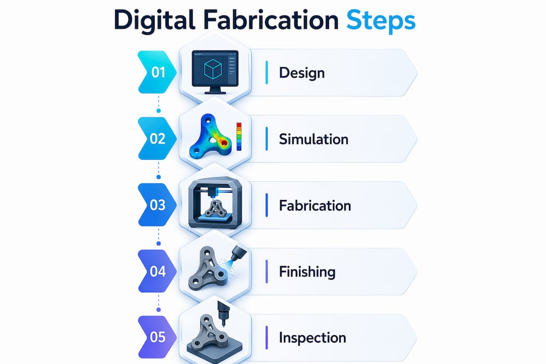
Infographic illustrating five prototyping steps

Tools and materials comparison

The right tool depends on what you are testing. Here is a direct comparison of the most common prototyping methods:

Method Best for Material options Speed Cost
FDM 3D printing Fit, form, and light functional tests PLA, PETG, ABS, Nylon, TPU Fast (hours) Low
SLA/resin printing Fine detail, smooth surfaces Photopolymer resins Fast (hours) Low to medium
CNC machining High-stress mechanical parts Aluminum, steel, acetal Medium (days) Medium to high
Urethane casting Small batch functional parts Polyurethane resins Medium Medium
Injection mold tooling Production-intent validation Any thermoplastic Slow (weeks) High

Tooling and materials for prototypes vary widely; production-intent materials are ideal but substitutions balance cost and functionality. FDM printing with Nylon or PETG, for example, handles most mechanical validation tasks at a fraction of CNC cost.

Pro Tip: Match your material to your test, not to the final product spec. If you are testing snap-fit geometry, PLA works fine. If you are testing fatigue under cyclic load, use the production material or its closest analog.

How do you create a functional prototype step by step?

The functional prototype process follows a clear sequence. Skipping steps does not save time. It creates rework.

  1. Define the test question. Write one sentence describing what the prototype must prove. “This bracket must support 50 lbs without deflecting more than 2mm.” Every decision after this flows from that sentence.

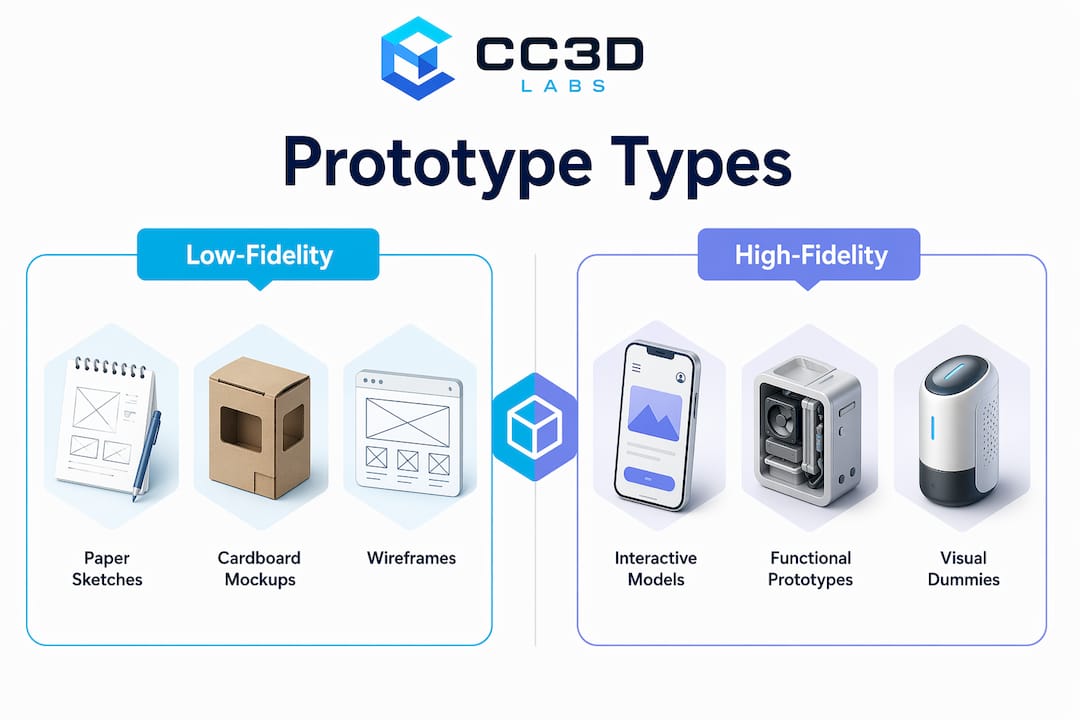
  2. Sketch low-fidelity concepts. Hand sketches or rough digital wireframes identify geometry and assembly logic before committing to CAD. This step takes hours, not days, and catches obvious problems early.

  3. Build the CAD model. Use Fusion 360, SolidWorks, or Onshape to create a parametric model. Design for the manufacturing method you plan to use. FDM parts need wall thickness above 1.2mm and should avoid unsupported overhangs beyond 45 degrees.

  4. Prepare and print or machine the part. Export your CAD file as an STL or STEP file. For FDM printing, slice the file in software like Bambu Studio, Cura, or PrusaSlicer. Set infill, layer height, and support strategy based on the functional load the part will carry.

  5. Assemble and conduct initial internal testing. Fit the prototype into its intended assembly context. Check clearances, fastener alignment, and mechanical travel. Document every failure point with photos and measurements.

  6. Iterate the design. Return to CAD, correct the identified issues, and reprint. For iterative prototyping to work efficiently, each iteration should address only the issues found in the previous test. Changing multiple variables at once makes it impossible to know what fixed the problem.

  7. Prepare for user testing. Once internal testing confirms basic function, move to external validation with real users. This is where most teams underinvest.

Choosing manufacturing methods matched to performance metrics is critical at step four. A part tested for fluid flow needs watertight walls, which FDM alone may not provide without post-processing. A part tested for impact resistance needs ABS or Nylon, not PLA.

How do you test and validate functional prototypes effectively?

Run tests with real users, not just your team

Testing a prototype with 5 real users uncovers 85% of usability issues. That finding from usability research holds true for physical products as much as software. Five users is not a large sample. It is the minimum effective dose for surfacing the most critical problems.

Internal team feedback is not a substitute for user testing. Engineers and designers carry domain expertise that blinds them to usability flaws. A team member who designed the assembly sequence will not struggle with it. A first-time user will. Avoid confusing internal feedback with real user validation, because domain expertise consistently obscures usability problems.

Common pitfalls to avoid

  • Testing too late. Waiting until the prototype is “ready” delays feedback by weeks. Test rough versions early.
  • Changing too many variables between iterations. One change per cycle keeps your data clean.
  • Ignoring failure modes. If a part breaks during testing, that is data. Document it, do not discard it.
  • Skipping quantitative metrics. Subjective feedback like “it feels loose” needs a measurement behind it. Define pass/fail criteria before testing begins.
  • Over-finishing the prototype. Sanding, painting, and polishing a prototype before function is confirmed wastes time and distorts user feedback.

When to stop prototyping

Stop prototyping when three consecutive user tests yield no new issues. Further refinement at that point wastes resources and delays production. The prototype has served its purpose. Shift focus to production tooling and manufacturing documentation.

“Functional prototypes are experiments for validation, not final products.” — A Practical Guide to Prototyping

That framing changes how you approach every build. An experiment that fails is still a success if it answers the question.

Pro Tip: Write your test criteria before you build the prototype. If you cannot define what “pass” looks like, you are not ready to test.

3D printing vs. other prototyping methods: which should you choose?

The choice of prototyping method determines what questions you can answer. No single method covers every scenario. Here is how the most common approaches compare for functional engineering prototypes:

Method Geometric complexity Functional accuracy Lead time Cost per part
FDM 3D printing High Medium (material dependent) Hours Very low
SLA printing Very high Medium (brittle resins) Hours Low
CNC machining Medium Very high 1–5 days High
Urethane casting High High 3–7 days Medium
Sheet metal fabrication Low Very high 3–10 days Medium to high

FDM 3D printing wins on speed and cost for early-stage functional tests. It handles complex geometry that CNC cannot reach without multi-axis setups. The tradeoff is material performance. FDM parts printed in standard PLA will not survive high-temperature or high-stress environments. For those conditions, CNC machining in aluminum or engineering-grade filaments like PEEK and carbon-fiber-reinforced Nylon close the gap.

Functional prototyping acts as a systematic validation gateway, aligning manufacturing methods with performance tests. That means the method you choose should be driven by the test parameter, not by habit or convenience. If you are validating a load-bearing bracket, CNC aluminum gives you real-world data. If you are validating assembly geometry, FDM is faster and cheaper. You can learn more about choosing the right 3D printing type for specific prototype and production goals.

Key Takeaways

Functional prototyping succeeds when you define specific test objectives, match your manufacturing method to those objectives, and validate with real users before investing in production tooling.

Point Details
Define objectives first Clear functional goals increase market success rates and prevent costly late-stage redesigns.
Match method to test FDM suits geometry and fit tests; CNC machining suits high-stress mechanical validation.
Test with real users Five users uncover 85% of usability issues that internal teams consistently miss.
Iterate one change at a time Changing multiple variables between builds makes it impossible to isolate what worked.
Know when to stop Three consecutive tests with no new findings signal the prototype has done its job.

What I’ve learned after watching hundreds of prototypes fail

The most consistent mistake I see product developers make is treating the prototype as a preview of the final product. They spend weeks perfecting surface finish and color before the core mechanism has been tested once. That instinct is understandable. Showing a polished prototype to stakeholders feels safer. But over-investing in prototype fidelity too early is one of the most documented failure modes in product development. Build only what is necessary to answer the specific question in front of you.

The second mistake is using the engineering team as the primary test audience. I have watched teams convince themselves a product is ready based on internal reviews, then see it fail immediately in user testing. Your team knows too much. They know the workarounds, the intended assembly sequence, the quirks. Real users do not. Get the prototype in front of people who have never seen it as early as possible, even if it is rough.

The third lesson is about method selection. Engineers often default to the method they know best rather than the method that fits the test. If your question is about ergonomics and grip, a foam model answers it faster than a printed part. If your question is about thermal performance, no amount of FDM printing replaces a test with the actual material. Align the method to the question, every time. That discipline is what separates teams that iterate fast from teams that spin their wheels.

— Justin

How Cc3dlabs supports your prototype builds

Product developers near Philadelphia and across the country use Cc3dlabs for on-demand filament-based 3D printing that fits directly into the iterative prototype cycle. Whether you need a single test part overnight or a batch of functional assemblies for user testing, the turnaround is built for speed.

https://cc3dlabs.com

Cc3dlabs offers professional 3D printing services for prototypes and functional parts, including multi-material options and CAD support for teams that need design-to-print help. The project gallery shows real functional parts across industries, from mechanical assemblies to enclosures. If you want to see what filament-based printing can do for your next prototype, request a free online estimate directly on the site.

FAQ

What is a functional prototype?

A functional prototype is a working model that performs the core functions of a product under realistic conditions. It is used to validate design decisions before committing to production tooling.

How many users do you need to test a prototype?

Testing with a handful of real users uncovers the large majority of usability problems. That threshold applies to physical product testing as well as software usability research.

When should you stop iterating on a prototype?

Stop prototyping when three consecutive user testing rounds produce no new findings. At that point, the design is validated and resources should shift to production preparation.

Is 3D printing good enough for functional prototypes?

FDM 3D printing handles fit, form, and light mechanical testing effectively. For high-stress or high-temperature applications, CNC machining or engineering-grade filaments like Nylon and PEEK are more appropriate.

What is the biggest mistake in functional prototyping?

Over-investing in prototype fidelity before answering the core functional question. Build the minimum version that tests what you need to know, then refine based on real data.

Engineer inspecting 3D printed object closely

The Role of Layer Adhesion in 3D Prints: A Pro Guide


TL;DR:

  • Layer adhesion in 3D printing depends on polymer fusion and chain entanglement before the interface freezes.
  • Controlling factors such as nozzle temperature, build plate heat, fan speed, and part orientation is essential for optimizing bond strength.

Layer adhesion in 3D printing is defined as the interlayer bond strength formed when successive layers of molten polymer fuse together before the interface freezes. This bond quality is the single most important factor determining whether a printed part behaves as a solid, monolithic object or a laminated stack that splits under load. The role of layer adhesion in 3D prints extends far beyond surface appearance. It governs tensile strength, failure mode, and long-term durability. Understanding interlayer bonding, the industry’s standard term for this phenomenon, is non-negotiable for anyone producing functional parts with FDM or FFF technology.

What factors most influence layer adhesion quality in 3D printing?

Layer adhesion is fundamentally a polymer welding problem. A fresh bead must wet, contact, and fuse with the previous layer while both surfaces remain above the glass transition or crystallization threshold. Once the interface freezes, bond strength plateaus and no amount of downstream heat will recover it.

Several variables control whether that fusion window stays open long enough:

  • Nozzle temperature. Higher melt temperatures increase polymer chain mobility and extend the fusion window. Prusa recommends adjusting printing temperature in 5°C increments for PLA to find the adhesion sweet spot without burning the material.
  • Cooling fan speed. Aggressive cooling locks the interface before chains can entangle. For ABS, Prusa explicitly recommends running the fan off entirely and using an enclosure to prevent delamination.
  • Layer thickness. Thinner layers produce stronger bonds. A 2026 Springer study found that PETG loses roughly 50% of shear strength at higher layer thicknesses, while PLA drops about 29%. Thinner layers mean more contact area and longer thermal exposure per unit of height.
  • Build plate temperature. HIPS showed improved interlayer bond quality at approximately 105°C build plate temperature, while PP suffered from warping and voids when plate temperature was mismatched. Molecular diffusion at the interface depends on sustained heat from below.
  • Ambient environment. Drafts and humidity disrupt the thermal profile around the part. Thermal gradients from the bed, enclosure, and environment influence void formation and residual stresses that degrade adhesion beyond nozzle temperature alone.

Pro Tip: Never treat nozzle temperature as the only thermal lever. Build plate temperature, enclosure heat, and fan speed all shape the time-temperature history at the interface. Tune them together, not in isolation.

How does layer adhesion affect mechanical performance and failure modes?

Hands adjusting 3D printer nozzle temperature control

Weak interlayer bonding creates a predictable failure path. Load applied perpendicular to the layer lines generates peel stress at the weld lines, and the part splits along those interfaces rather than through the material itself. This is the defining characteristic of anisotropic behavior in FDM parts: strength along the print axis is always lower than strength within a layer plane.

Mechanical testing reveals how adhesion quality shows up in real failure data:

  1. Tensile testing perpendicular to layers exposes the weakest bond directly. Parts with poor adhesion fracture cleanly at layer interfaces at loads well below the material’s rated tensile strength.
  2. Shear testing measures how well layers resist sliding against each other. Mechanical interlocking between bi-material FDM joints can reach shear strength above 24 MPa, compared to roughly 21.7 MPa for alternate deposition without interlocking geometry.
  3. Bending tests reveal combined tension and compression across layers. Delamination typically initiates on the tension face where peel stress concentrates.
  4. Fracture surface analysis is the most practical diagnostic. A smooth shear fracture indicates good bonding. A rough, stepped fracture surface signals adhesion failure at the interface rather than bulk material failure.
Material Layer thickness effect Approximate strength loss
PLA Increased thickness reduces bond ~29% at higher layer heights
PETG More sensitive to thickness ~50% at higher layer heights
PEKK Crystallization-controlled 93.9 MPa tensile via cooling regulation
HIPS Build plate temperature sensitive Improved at ~105°C plate temp

The table above makes one point clear: material choice and layer thickness interact. You cannot apply PLA settings to PETG and expect equivalent bond quality.

Design decisions compound the risk. Parts oriented so that the primary load runs parallel to layer lines perform far better than parts where load pulls layers apart. For strength-critical parts, print orientation is as important as material selection.

Infographic illustrating key factors of layer adhesion

What advanced techniques and design strategies enhance layer adhesion?

Professional-grade adhesion requires going beyond default slicer presets. The following approaches produce measurable improvements in interlayer bond strength:

  • Mechanical interlocking geometry. When chemical adhesion between two materials is limited, geometry does the work. Dovetail or interlocking features at bi-material interfaces limit interlayer sliding under shear and push shear strength above what surface bonding alone achieves.
  • Extrusion multiplier tuning. Slight over-extrusion (typically 1–5% above nominal) increases contact pressure between the fresh bead and the previous layer. This widens the fusion zone without requiring a temperature increase that might cause stringing or dimensional error.
  • Controlled crystallization for high-performance polymers. PEKK and similar semi-crystalline materials require cooling regulation to stay below the crystallization threshold during printing. Printed PEKK parts achieved tensile strength of 93.9 MPa when cooling was managed to preserve chain mobility. Premature crystallization induces brittleness and kills bond quality.
  • Enclosures for warp-prone materials. ABS, ASA, and PC all benefit from a heated enclosure that keeps the ambient temperature above the material’s glass transition. This extends the fusion window for every layer deposited.
  • Layer orientation strategy. Aligning the print so that critical load paths run parallel to layer planes, not perpendicular to them, avoids peel stress at weld lines entirely. This is a design decision, not a slicer setting, and it belongs in the part design phase.

Pro Tip: When printing multi-material parts, add a small interlocking feature at the interface zone rather than relying on surface contact alone. Even a simple tongue-and-groove profile dramatically increases shear resistance where chemical bonding is limited.

Common challenges with layer adhesion and how to troubleshoot them

Most real-world FDM delamination comes from thermal mismatch and poor interface control, not from defective filament or hardware failure. Knowing what to look for narrows the diagnosis quickly.

  • Visible layer separation or cracking. The first check is always temperature. Raise nozzle temperature in 5°C steps. For ABS, confirm the fan is off and the enclosure is sealed against drafts.
  • Weak fracture along layer lines under light load. This points to insufficient fusion time. Reduce print speed to keep the interface hot longer, or increase nozzle temperature. Check that the wall thickness is adequate for the load the part will carry.
  • Delamination only at specific heights. Look for environmental causes: a nearby vent, a door opening during the print, or a section of the part that cools faster due to geometry. Drafts cause localized thermal drops that freeze interfaces prematurely.
  • Inconsistent bond quality across a batch. Filament moisture is the most common culprit. Wet filament produces steam voids at the interface that destroy bond continuity. Dry filament at the manufacturer’s recommended temperature before printing.
  • Rough fracture surface on a failed part. A rough, granular fracture face confirms adhesion failure rather than bulk material failure. Smooth fracture surfaces indicate the bond held and the material itself failed, which is the correct outcome for a well-printed part.

Thermal profile control is more effective than simply raising temperature across the board. Systematic adjustment of nozzle temperature, bed temperature, fan speed, and enclosure conditions together produces consistent results. Changing one variable at a time makes it possible to identify the actual cause rather than masking it.

Key takeaways

Strong interlayer bonding requires controlling the full thermal environment at the interface, not just the nozzle temperature, and designing parts so critical loads run parallel to layer planes rather than pulling layers apart.

Point Details
Adhesion is a welding problem Polymer chains must entangle before the interface freezes; once frozen, bond strength cannot recover.
Layer thickness drives strength loss PETG loses ~50% shear strength at higher layer thicknesses; thinner layers consistently outperform thicker ones.
Thermal environment matters beyond the nozzle Build plate temperature, enclosures, and draft control all shape the fusion window at every layer.
Mechanical interlocking compensates for weak chemistry Interlocking geometry at bi-material joints pushes shear strength above 24 MPa where surface bonding falls short.
Fracture surface analysis beats visual inspection Rough fracture faces confirm adhesion failure; smooth faces confirm the bond held and material failed correctly.

Why I think most 3D printing teams underestimate thermal environment

The industry conversation about layer adhesion almost always centers on nozzle temperature. Raise it, lower it, find the sweet spot. That framing is too narrow, and I have seen it lead experienced teams in circles for weeks.

The interface does not care only about what temperature the nozzle deposited the material at. It cares about the entire time-temperature history from deposition to freeze. A draft from an HVAC vent three feet away can collapse bond quality on one side of a tall part while the other side prints perfectly. A build plate running 10°C below spec on a HIPS job produces voids that look like filament defects but are actually thermal failures.

What I find most useful is treating the printer as a thermal system, not a mechanical one. Before changing any slicer setting, I look at the fracture surface of a failed part. Rough and stepped means the interface never fused properly. Smooth and planar means the bond held and something else failed. That single observation cuts diagnostic time in half.

The other thing I push hard on is print orientation. Most practitioners treat it as a geometry problem. It is actually a stress engineering problem. Orienting a bracket so the primary load runs along the layer plane instead of across it can double effective part strength without changing a single print parameter. That is free performance, and it costs nothing except a few minutes of thought during prototype design.

Continuous experimentation with materials and parameters is the only way to build real intuition here. No datasheet replaces the knowledge you get from deliberately breaking parts and reading the fracture surfaces.

— Justin

Cc3dlabs delivers prints where layer bonding is never a compromise

https://cc3dlabs.com

At Cc3dlabs, near Philadelphia, every filament-based print goes through a process tuned for the specific material and part geometry. That means build plate temperatures dialed for the polymer, enclosures used where ABS or ASA demand them, and layer thickness selected for the strength the part actually needs. The team handles everything from single prototypes to batch production runs, with material consultation built into the workflow. If you need parts that hold up under real mechanical loads, explore Cc3dlabs’ professional 3D printing services or get a free online estimate to see what optimized layer bonding looks like in practice.

FAQ

What is layer adhesion in 3D printing?

Layer adhesion is the bond formed between successive layers of deposited polymer in FDM or FFF printing. Bond strength depends on polymer chain entanglement and fusion before the interface freezes by glass transition or crystallization.

Why does layer thickness affect interlayer bond strength?

Thinner layers maintain more contact area and longer thermal exposure between the fresh bead and the previous layer. A 2026 Springer study found PETG loses approximately 50% of shear strength at higher layer thicknesses compared to 0.1mm layers.

How do I fix layer separation in ABS prints?

Turn the cooling fan off, use an enclosure to block drafts, and raise nozzle temperature in 5°C increments. Most ABS delamination comes from thermal mismatch and ambient air cooling the interface before fusion completes.

Does print orientation affect layer adhesion performance?

Print orientation determines whether loads run parallel or perpendicular to layer planes. Parts oriented so critical loads run parallel to the layer plane avoid peel stress at weld lines and perform significantly better under mechanical loading.

What does a rough fracture surface on a failed print indicate?

A rough, stepped fracture surface confirms that the interlayer bond failed rather than the bulk material. A smooth fracture surface means the bond held correctly and the material itself reached its strength limit.

Engineer scanning a legacy car part with 3D scanner

Scanning for Legacy Part Reproduction: A 2026 Guide


TL;DR:

  • D scanning transforms physical legacy parts into detailed digital models for reproduction and inspection. It uses various methods, including structured light, laser, photogrammetry, and CT scanning, depending on the required accuracy and internal complexity. Proper workflow integration and documentation are essential to qualify reproduced parts in regulated industries and maximize the value of scan data.

3D scanning is the foundational step in legacy part reproduction, converting physical components into accurate digital models that engineers can inspect, modify, and manufacture from. The process, formally called reverse engineering through digitization, captures geometry down to fractions of a millimeter. This makes it possible to reproduce parts that have no surviving drawings, no original CAD files, and no active supplier. The role of scanning in legacy part reproduction goes beyond simple copying. It creates a verified digital record that supports future redesign, quality inspection, and regulatory traceability.

What scanning technologies are used in legacy part reproduction?

Four primary technologies drive 3D scanning in reproduction workflows: structured light scanning, laser scanning, photogrammetry, and industrial Computed Tomography (CT) scanning. Each method captures different types of geometry with different levels of accuracy and cost.

Structured light scanners project a grid pattern onto a surface and measure how the pattern deforms. This method captures external geometry with high resolution and works well for machined metal parts, housings, and connectors. Laser scanning uses a similar principle but projects a laser line instead of a grid, making it effective for larger parts and freeform surfaces.

High-resolution photogrammetry offers non-invasive, accurate 3D documentation that preserves surface details with minimal human intervention. It works by processing overlapping photographs through algorithmic pipelines. Photogrammetry is best suited for capturing texture and surface character rather than tight mechanical tolerances.

Industrial CT scanning stands apart from the other three methods. CT scanning generates non-destructive 3D volumetric models that reveal internal features, hidden cavities, and wall thicknesses without disassembling or damaging the original part. This makes CT the only viable option when internal geometry drives the function of the component.

Technology Best for Accuracy Key limitation
Structured light External surfaces, small parts Very high Limited to line of sight
Laser scanning Large parts, freeform surfaces High Surface reflectivity issues
Photogrammetry Texture, surface character Moderate Lower dimensional accuracy
Industrial CT Internal features, assemblies Very high High cost, slow throughput

Pro Tip: For parts with both complex external geometry and critical internal channels, combine structured light scanning for the exterior with CT scanning for internal features. This gives you a complete digital model without destroying the original part.

Infographic illustrating 3D scanning process steps

How does scanning integrate into the reverse engineering workflow?

Scanning is one step inside a larger reverse engineering process. Getting that step right requires a structured approach from the moment the physical part arrives.

  1. Initial assessment. Examine the part for damage, wear, and surface condition. Identify which features are functional and which are cosmetic. This determines which scanning method to use and where to focus resolution.
  2. Scan execution. Set up the scanner according to part size, material reflectivity, and required accuracy. For shiny metal surfaces, apply a temporary matte spray to reduce noise. Capture multiple passes to cover all angles.
  3. Data processing. Raw scan data often contains noise and incomplete surfaces. Dedicated software such as Geomagic Design X or Artec Studio processes the point cloud into a clean mesh. Skilled operators are required at this stage. Version control of scan files starts here.
  4. CAD reconstruction. Convert the mesh into a parametric CAD model using tools like SolidWorks or CATIA. This step requires engineering judgment, not just geometry tracing. The engineer must decide which features are nominal and which reflect wear or damage.
  5. Validation. Compare the reconstructed CAD model against the original scan data. Deviation maps highlight where the model diverges from the physical part. Acceptable tolerances depend on the application.

Pro Tip: Document engineering intent at every step. Note why a feature was modeled a certain way, especially when the physical part shows wear. That reasoning becomes part of the evidence chain needed for qualification in regulated industries.

Establishing a traceable qualification workflow that links part assessment, material identification, and scan data version control is the defining challenge in regulated sectors. Aerospace, defense, and medical manufacturers cannot simply reproduce geometry. They must prove the reproduction meets the original performance standard.

What are the benefits and challenges of 3D scanning for legacy parts?

The benefits of part scanning are concrete and measurable. professional handheld 3D scanning (accuracy to ~0.1 mm) captures accurate, watertight geometry,, capturing fine surface details and complex mechanical interfaces that manual measurement cannot reliably document. That level of accuracy eliminates the guesswork that comes with calipers and hand sketches.

Key benefits include:

  • Geometry capture without contact. Scanning preserves fragile or worn parts during the documentation process.
  • Speed. A structured light scanner can capture a full part surface in minutes. Manual measurement of the same part could take hours.
  • Complex feature documentation. Freeform surfaces, compound curves, and organic shapes that are impossible to measure manually are captured completely.
  • Digital twin creation. The scan becomes a permanent digital record for future inspection, redesign, or reproduction.

The challenges are equally real. Many reverse engineering projects stall because teams treat the work as a scanning task rather than a full data, compliance, and workflow integration effort. Geometry capture is necessary but not sufficient.

Specific challenges engineers face:

  • Data volume. High-resolution scans generate large point cloud files that require significant computing resources and organized storage.
  • Engineering intent. A scan captures what the part looks like now, not what it was designed to be. Worn features, corrosion, and deformation all appear in the scan data.
  • Material validation. Additive manufacturing material behavior differs from original manufacturing methods. Geometry matching alone does not qualify a reproduced part for service.
  • Audit trails. Regulated industries require documented evidence chains linking every decision from scan to final part.

Pro Tip: Build your evidence chain from day one. Log the scan date, operator, equipment calibration record, software version, and every processing decision. Retrofitting this documentation after the fact is expensive and often incomplete.

How do manufacturers apply scanning in practical production workflows?

The practical applications of digitization for legacy parts extend well beyond creating a one-time reproduction. Manufacturers use scan data across multiple production and maintenance scenarios.

Technicians discussing 3D printed spare part on factory floor

High-fidelity scanning combined with additive manufacturing connects classical part geometry with modern digital production methods. A scanned digital twin can feed directly into a 3D printer for rapid prototyping, or into a CNC machining center for subtractive production. The same scan data supports both paths, which reduces lead time when a manufacturer needs to evaluate multiple production options quickly.

You can also use scan-derived digital twins for design accuracy and prototyping improvements. Engineers overlay the scan of a worn part against the original CAD model to measure how the part has changed in service. This data informs redesign decisions and helps predict future failure modes.

Application Scanning input Outcome
Spare part reproduction Full surface scan Replacement part manufactured to original geometry
Wear analysis Scan vs. nominal CAD Quantified deviation map for maintenance planning
Rapid prototyping Scan to mesh to print Physical prototype in hours for fit and function testing
Aftermarket servicing Scan of discontinued part New supplier tooling created without original drawings
Quality inspection Scan of produced part Automated comparison against design intent

Aftermarket and legacy vehicle servicing represent one of the highest-value applications. When a manufacturer discontinues a component and the original tooling no longer exists, a high quality 3D scan of a surviving example becomes the only path to reproduction. This is common in aerospace MRO (maintenance, repair, and overhaul), classic vehicle restoration, and industrial equipment servicing.

The production efficiency gains are direct. Eliminating manual measurement and manual redrawing removes two of the most error-prone steps in legacy part reproduction. Scan data feeds manufacturing equipment directly, which reduces the number of iterations needed to achieve a conforming part.

Key Takeaways

Scanning is the critical first step in legacy part reproduction, but traceable workflow integration, material validation, and engineering documentation determine whether a reproduced part qualifies for service.

Point Details
Scanning precision matters professional handheld scanners capture geometry to roughly 0.05–0.1 mm (50–100 microns), far beyond manual measurement capability.
Technology selection is part-specific CT scanning is required for internal features; structured light works best for external surfaces.
Workflow integration is non-negotiable Reverse engineering projects fail when teams treat scanning as the only task rather than one step in a documented process.
Material validation is separate from geometry A geometrically accurate scan does not automatically qualify a reproduced part, especially in regulated industries.
Digital twins extend value beyond reproduction Scan data supports wear analysis, quality inspection, and future redesign, not just one-time part replication.

Why scanning alone will not save your legacy part program

Most manufacturers I work with come to scanning with the right instinct but the wrong expectation. They assume that once the scan is done, the hard part is over. The opposite is true.

The scan gives you geometry. What it does not give you is engineering intent, material specification, or a qualification record. A worn part scanned at high accuracy still gives you a worn part. The engineer has to decide which dimensions represent the design and which represent 40 years of service. That judgment call is not in the scan file.

The manufacturers who succeed with legacy reproduction treat the scan as the beginning of a documented evidence chain, not the end of a measurement task. They track every decision, every software version, and every material substitution. In aerospace and defense, that chain is what gets a part approved. In commercial manufacturing, it is what prevents a costly recall.

The shift I see in 2026 is toward combined workflows where scanning, CAD reconstruction, additive manufacturing, and inspection all share the same data thread. Tools like Authentise and similar manufacturing execution platforms are making this more accessible. But the discipline of documentation still comes from the engineering team, not the software. If you are starting a legacy part program, build the process before you buy the scanner.

— Justin

Cc3dlabs scanning and reproduction services for legacy parts

Cc3dlabs operates a professional 3D scanning lab near Philadelphia that supports manufacturers, engineers, and product developers with professional handheld 3D scanning (accuracy to ~0.1 mm) and scan-to-CAD processing. The team handles structured light scanning for external geometry and works with clients on full reverse engineering workflows from initial scan through digital twin creation.

https://cc3dlabs.com

For manufacturers who need to move from scan data to physical parts, Cc3dlabs connects scanning directly to 3D printing and production services that support both rapid prototyping and functional part reproduction. Whether you need a single replacement component or a documented reproduction workflow for a regulated application, Cc3dlabs provides the precision and traceability support the job requires. Request a free online estimate to get started.

FAQ

What is the role of scanning in legacy part reproduction?

3D scanning converts a physical legacy part into an accurate digital model that engineers can use to reproduce, inspect, or redesign the component. It is the foundational step in reverse engineering when no original drawings or CAD files exist.

Which scanning method is best for internal part features?

Industrial CT scanning is the correct method for internal features. It generates non-destructive 3D volumetric models of hidden cavities, wall thicknesses, and internal assemblies without altering the original part.

Does scanning alone qualify a part for reproduction in regulated industries?

Scanning alone does not qualify a part. Regulated industries require a traceable qualification workflow that documents part assessment, material identification, scan data version control, and material validation alongside the geometric scan data.

How accurate is professional handheld 3D scanning (accuracy to ~0.1 mm)?

professional handheld 3D scanning (accuracy to ~0.1 mm) captures accurate, watertight geometry,. That level of accuracy captures fine mechanical interfaces and complex surface details that manual measurement methods cannot reliably document.

What software is used to process raw scan data into CAD models?

Tools like Geomagic Design X and Artec Studio process raw point cloud data into clean meshes. Engineers then use parametric CAD platforms such as SolidWorks or CATIA to reconstruct manufacturable models from the processed scan data.

Engineer adjusting 3D printed prototype at bench

Print Orientation in 3D Printing: A Practical Guide


TL;DR:

  • Print orientation in 3D printing determines a model’s position on the build plate, affecting strength, finish, support needs, and print time. Properly aligning layers with the primary load direction enhances part durability, while surface quality depends on how flat surfaces are oriented relative to the build plate. Using the correct orientation minimizes supports and reduces overall production costs and duration.

Print orientation is defined as the position and direction a 3D model occupies on the build plate before and during printing. That single decision shapes the part’s mechanical strength, surface finish, support material needs, and total print time. Hobbyists and product developers alike often treat orientation as an afterthought. Professionals at shops like Cc3dlabs treat it as the first design decision. This guide breaks down every major effect of print orientation so you can make smarter choices before your next print starts.

What is print orientation and why does it matter in 3D printing?

Print orientation, known in manufacturing as build orientation, is the angle and axis at which a model is placed relative to the build plate in a 3D printer. In FDM (Fused Deposition Modeling) printing, the printer deposits material layer by layer from the bottom up. The direction those layers stack determines almost everything about the final part.

Think of it like wood grain. A plank of wood is strong along the grain and splits easily across it. FDM printed parts behave the same way. FDM parts are anisotropic, meaning their strength varies depending on the direction of the applied force relative to the layer lines. That single fact is the foundation of every orientation decision you will make.

Orientation also controls how tall a print is, which directly affects how many layers the printer must deposit. More layers mean more time. The wrong orientation can also force the slicer to generate support structures for overhangs, adding material waste and post-processing work. Getting orientation right before you hit print is the highest-leverage decision in the entire workflow.

How does print orientation affect the strength of a 3D printed part?

The bond between two adjacent layers in an FDM print is always weaker than the continuous filament running within a single layer. Stress applied perpendicular to layer interfaces causes delamination and reduced tensile strength. That is the core mechanical risk of poor orientation.

The fix is straightforward: align the primary load direction with the layer lines, not across them. If a bracket will be pulled along its length, print it so the layers run lengthwise. If a clip will flex open and closed, orient it so the bending stress runs parallel to the layers, not perpendicular to them. This is how you validate 3D designs for real-world loads before committing to a production run.

Infographic comparing strength and print quality effects by orientation

SLA and SLS technologies are less sensitive to this issue. SLA parts cure in a resin pool and have more isotropic properties. SLS parts are sintered in powder and show minimal directional weakness. But for FDM, which covers the vast majority of desktop and professional filament printers, orientation is a structural decision, not just a visual one.

Pro Tip: Orient load-bearing surfaces parallel to the build plate. That keeps the strongest filament continuity aligned with the direction of stress and dramatically reduces the risk of layer separation under load.

What impact does print orientation have on surface finish and aesthetics?

Surface finish is where orientation choices become visible to anyone who picks up the part. Flat surfaces printed parallel to the build plate produce the smoothest result because the layers stack cleanly on top of each other with minimal visible stepping.

Angled or vertical faces tell a different story. When a curved or diagonal surface rises along the Z-axis, each layer creates a small horizontal step. This is called the stair-stepping effect, and it becomes more pronounced as the surface angle becomes shallower relative to the build plate. A 15-degree slope will show far more stepping than a 60-degree slope.

Here are the key rules for orientation when appearance matters:

  • Cosmetic faces go down or sideways. Place the most visible surface against the build plate or parallel to it for the smoothest result.
  • Avoid the Z-axis for precision fits. Critical mating surfaces oriented along the Z-axis lose dimensional accuracy due to stair-stepping, which can ruin a snap-fit or press-fit joint.
  • Curved features need careful planning. Cylinders printed vertically show stepping around their circumference. Printing them horizontally produces a smoother outer wall but weakens the part along its length.
  • Prioritize the surface the end user will see. If only one face of a part is visible in its final assembly, orient that face for the best finish, even if it means a slightly weaker structure elsewhere.

The trade-off between strength and surface finish is the most common tension in orientation decisions. There is rarely a single orientation that maximizes both. The key is knowing which property matters more for your specific part.

How does print orientation influence support material usage and print efficiency?

Supports are structures the slicer generates automatically to hold up any portion of the model that overhangs more than roughly 45 degrees from vertical. Overhangs greater than 45 degrees require support material, which increases filament consumption and adds post-processing time for removal and sanding. Optimizing orientation to minimize supports can reduce filament consumption by 20–50%. That is a significant cost and time saving on any print, and it compounds across batch production runs.

Print time is the second efficiency factor. Taller parts require more layers, and each additional layer adds time. A part printed upright at 120mm tall will take considerably longer than the same part printed flat at 30mm tall. Reducing vertical height by rotating the model is one of the fastest ways to cut print duration without changing any slicer settings.

The table below shows how the three main orientation strategies compare across the key efficiency metrics:

Orientation Support volume Print time Surface quality Strength direction
Flat (horizontal) Low Fast High on top face Strong along XY plane
Upright (vertical) Medium Slow Moderate on sides Strong along Z-axis
Angled (tilted) High Medium Variable Distributed across axes

Pro Tip: Decide on orientation during the design phase, not after the model is finished. Small geometry changes, like adding a flat face or chamfering an overhang, can eliminate entire support structures and save hours of print time and post-processing.

You can find more detail on reducing waste and labor through smart orientation in this guide to cutting 3D printing costs.

What are the main print orientation types in 3D printing?

The three primary orientation types in 3D printing are flat, upright, and angled. Each produces a different balance of strength, finish, and efficiency.

3D prints showing flat, upright, and angled orientations

Flat orientation places the model with its largest face on the build plate. This minimizes print height, reduces supports, and produces the best surface finish on the top face. It is the default choice for wide, thin parts like brackets, panels, and trays.

Upright orientation stands the model on its smallest face, maximizing height along the Z-axis. This is useful when you need strength along the part’s length or when the bottom face has critical geometry that must be preserved. The trade-off is longer print times and more visible layer lines on the sides.

Angled orientation tilts the model at a custom angle, often 30–45 degrees. This distributes layer lines across multiple surfaces, which can improve strength in multiple directions simultaneously. It often increases support volume, so it works best when the geometry has no clean flat face to rest on.

For context, the concept of orientation also appears in standard 2D document printing. Portrait orientation is taller than wide; landscape is wider than tall. Portrait suits vertical reading flow, while landscape favors horizontal data layouts like spreadsheets and charts. The analogy is useful: just as you choose a page orientation based on content layout, you choose a 3D build orientation based on part function.

2D orientation Aspect ratio Best use
Portrait Taller than wide Documents, letters, vertical images
Landscape Wider than tall Spreadsheets, presentations, wide graphics

In 3D printing, the logic scales up. The “layout” is the part’s geometry, and the “content” is its mechanical and aesthetic requirements.

How to set and choose the best print orientation for your project

Selecting the right orientation is a structured process, not a guess. Follow these steps to make a defensible decision every time.

  1. Identify the primary load direction. Ask where the part will experience the most stress. Align the layers to run parallel to that force, not across it.
  2. Identify the cosmetic surfaces. Determine which faces will be visible or need a smooth finish. Plan to orient those faces parallel to the build plate or away from the Z-axis.
  3. Assess overhang geometry. Rotate the model in your slicer, such as Ultimaker Cura, PrusaSlicer, or Bambu Studio, and look for overhangs greater than 45 degrees. Adjust orientation to eliminate as many as possible before adding supports.
  4. Check vertical height. Compare print time estimates at different orientations. A shorter Z-height almost always means a faster print. Use your slicer’s layer preview to confirm.
  5. Run a test print. For functional parts, print a small section or a simplified version at your chosen orientation before committing to the full part. This is standard practice in 3D part optimization workflows.
  6. Iterate based on results. No perfect orientation exists. Professionals treat orientation as an iterative decision that gets refined with each print. Document what worked and why.

Pro Tip: Prioritize end-use requirements before locking in orientation. A decorative part should be oriented for finish. A structural part should be oriented for strength. Trying to optimize both at once usually produces a part that excels at neither.

For more guidance on designing parts that print reliably from the start, see this resource on designing reliable prototypes.

Key takeaways

Print orientation is the single most impactful pre-print decision in FDM 3D printing, controlling strength, surface finish, support volume, and total print time simultaneously.

Point Details
Orientation controls strength Align layer lines with the primary load direction to prevent delamination and maximize tensile strength.
Surface finish depends on axis Flat surfaces parallel to the build plate are smoothest; Z-axis faces show the most stair-stepping.
Supports add cost and time Minimizing overhangs through smart orientation can cut filament use by 20–50% per print.
Taller prints take longer Reducing vertical height by rotating the model is the fastest way to shorten print duration.
Iteration is standard practice No single orientation is perfect; test, document, and refine based on actual part performance.

The trade-off no one talks about honestly

I have reviewed hundreds of parts that came in for printing with the orientation already locked in by the designer. The most common mistake is not choosing the wrong axis. It is assuming that one orientation can satisfy every requirement at once.

A hobbyist will orient a functional bracket for the best-looking surface finish, then wonder why it snapped under load. A product developer will orient a prototype for maximum strength, then spend an hour sanding off support scars from the mating face. Both are making the same error: treating orientation as a single-variable problem when it is always a multi-variable trade-off.

What I tell every client is this: write down the two most important properties for your part before you open the slicer. If strength ranks first, orient for strength and accept the surface finish you get. If appearance ranks first, orient for finish and reinforce the design with geometry, like ribs or gussets, to compensate for reduced layer strength. Trying to split the difference without a clear priority usually produces a mediocre result on both fronts.

The other thing worth saying plainly: slicers like PrusaSlicer and Bambu Studio have auto-orientation features. They are useful starting points, not final answers. They optimize for support reduction, not for your specific load case. Always override the auto-suggestion with your own analysis of how the part will actually be used.

— Justin

Get orientation right the first time with Cc3dlabs

https://cc3dlabs.com

Cc3dlabs, based near Philadelphia, applies professional orientation analysis to every custom filament print it produces. Whether you are printing a single prototype or a batch of functional parts, the team evaluates load direction, surface requirements, and support geometry before a single layer is deposited. That process is what separates a part that performs from one that just looks like it will.

If you want expert eyes on your next project, explore Cc3dlabs’ professional 3D printing services or browse the full range of on-demand printing options for prototypes and custom parts. Free online estimates are available, and the team supports both local pickup near Philadelphia and international shipping.

FAQ

What is print orientation in 3D printing?

Print orientation is the position and angle at which a 3D model is placed on the build plate before printing. It directly controls the part’s strength, surface finish, support requirements, and print time.

Which orientation produces the strongest FDM printed part?

The strongest orientation aligns the primary load direction parallel to the layer lines. Stress applied perpendicular to layer interfaces causes delamination, so the load vector should run along the filament layers, not across them.

How does orientation affect support material usage?

Overhangs greater than 45 degrees require support structures. Rotating a model to reduce steep overhangs can cut filament consumption by 20–50% and significantly reduce post-processing time.

What is the difference between portrait and landscape orientation?

In 2D printing, portrait orientation is taller than wide and suits vertical documents, while landscape is wider than tall and works best for horizontal layouts like spreadsheets and presentations. In 3D printing, the equivalent choices are flat, upright, and angled orientations based on part geometry and function.

Can slicing software choose the best orientation automatically?

Slicers like PrusaSlicer and Bambu Studio include auto-orientation tools that minimize supports, but they do not account for your specific load case or cosmetic priorities. Use auto-orientation as a starting point, then adjust based on how the part will actually be used.